


Engineering students' guide to single storey buildings
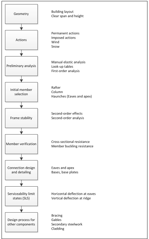
Although software will normally be used to achieve an efficient design, for an engineer who is new to designing single storey buildings it is important that they understand how the structure behaves, and how its different components interact. Eight steps are used to define a logical sequence for the main frames. This is then followed by design of the bracing, gables, secondary steelwork and cladding. Rules of thumb are included to help the designer quickly and efficiently arrive at a solution that is sensible for a given set of constraints.


[top]Stages of a project
The stages of a construction project are presented in ISE publication ‘Structural design – the engineer’s role’[1], which may be broadly summarised as follows:
- Project formulation - What it’s for, why is it being proposed, where is it etc.
- Assembling the data and developing the brief - Understanding the site and context.
- Scheme design - Looking at and developing options.
- Detailed design - Of the various components and elements.
- Information for construction - Drawings, specifications.
- Construction.
Many of these stages include aspects of engineering design. A characteristic of steel framed construction is that the constituent parts of the structure are manufactured off-site, with all the quality and speed-on-site benefits that are associated with such a form of construction. An implication of this, however, is that the design must be substantially complete before steelwork fabrication can begin. It is therefore important that the designer follows a logical sequence, as going back and revisiting earlier design decisions, once other parties involved have moved on to designing other parts of the building or manufacturing components, can be disproportionately expensive.
[top]Basic principles of good design
Some basic choices may have a significant impact on the ease, time and cost of both the fabrication and construction of a steel framed building. Principles to observe are:
- Keeping fabrication and construction in mind from the start will lead to the best possible solution.
- Keep the design simple and familiar (don’t use exotic solutions unless they are justified).
- Standardise where possible.
- Pay attention to interfaces.
[top]Anatomy of a portal framed building

The vast majority of single storey buildings in the UK are portal framed buildings. These were first widely used in the 1960s. During the 1970s and early 1980s they developed rapidly to become the predominant form of single storey construction.
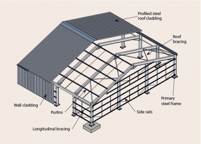
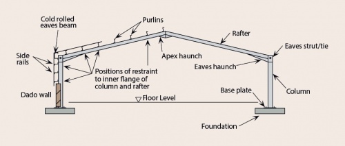
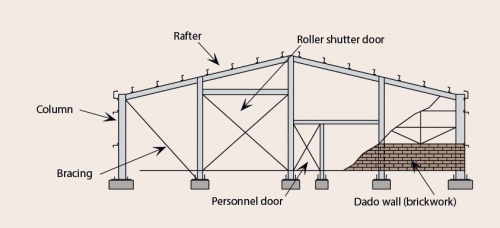
A portal framed building comprises a series of unbraced transverse frames, braced longitudinally. The primary steelwork consists of columns and rafters, which form the portal frames, and longitudinal bracing. The end frame (gable frame) can be either a portal frame or a braced arrangement of columns and rafters. The figures below show the principle building components of a portal frame building.
The secondary steelwork which supports the cladding consists of side rails for walls and purlins for the roof. The secondary steelwork also plays an important role in restraining the primary steelwork members against buckling out-of-plane.
The roof and wall cladding separate the enclosed space from the external environment and provide thermal and acoustic insulation. The cladding transfers loads to the secondary steelwork and restrains the flange of the purlin or rail to which it is attached.
A number of options are available for each of these parts of a portal framed building.

Portal framed structures - overview
Interfaces

For single storey buildings the interface between the primary steel frame and the building envelope, via the secondary steelwork, warrants particular attention. This is because the secondary steelwork and envelope both fulfil more than one role (as noted above). More than one designer may be involved in specifying these components, so clear communication of design assumptions is vital. Communication between designers and erectors is also vital. These issues are discussed in detail in SCI P346.
[top]The design process for the main frame
The most economical structures are often those produced using plastic design techniques, which in the UK are well established and have been used for over 40 years. Software, developed specifically for the analysis and design of portal frames, will generally be used for efficient design. However, to enable an understanding of the analysis, design and behaviour of portal framed structures this article presents design steps in a logical sequence. SCI P399 covers the design of portal frames to Eurocode 3, including plastic analysis and the verification of members.

[top]Step 1: Geometry
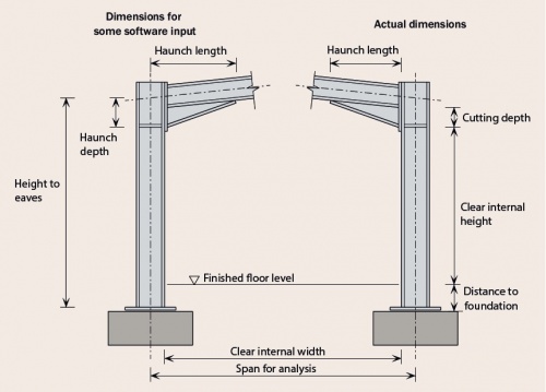

Establish the clear span and height based on the client’s requirements. The geometry used in the structural frame analysis should be a little conservative to allow for any potential changes in member size (section depth) but still maintaining the specified height from finished floor level to the underside of the haunches which cannot be changed.
[top]Step 2: Actions
Establish actions depending on location, site altitude and local topography. For the UK actions are defined in:
- BS EN 1991-1-1:2002[2] for densities, self-weight and imposed loads.
- BS EN 1991-1-3:2003+A1:2015[3] for snow loads.
- BS EN 1991-1-4:2005+A1:2010[4] for wind actions.
Permanent actions may be estimated, based on the selected cladding type. The different actions are combined according to BS EN 1990[5] (which recognises that they will not all be at their maximum value coincidentally).
Some typical weights of roofing materials are given in the table below.
| Roofing product | Weight (kN/m2) |
| Steel roof sheeting (single skin) | 0.07 – 0.12 |
| Aluminium roof sheeting (single skin) | 0.04 |
| Insulation (boards, per 25 mm thickness) | 0.07 |
| Insulation (glass fibre, per 100 mm thickness) | 0.01 |
| Liner trays (0.4 mm – 0.7 mm thickness) | 0.04 – 0.07 |
| Composite panels (40 mm – 100 mm thickness) | 0.1 – 0.15 |
| Steel purlins (distributed over the roof area) | 0.03 |
| Steel decking | 0.2 |
Equivalent horizontal forces
Equivalent horizontal forces (EHF) are not strictly actions, but are forces applied to the frame, in combination with other actions, to model the effect of frame imperfections. The simple approach of applying the EHF is recommended in SCI P399.
The Eurocode distinguishes the following types of imperfections to be taken into account:
- global imperfections for frames and bracing systems.
- local imperfections for individual members.
Refer to section 6.3 of BS EN 1993-1-1[6] for further information.
[top]Step 3: Preliminary analysis
Tables in Appendix A of SCI P399 may be used for preliminary sizing of frames with typical geometry. Alternatively sizing can be based on a preliminary manual analysis, which is simple to perform. In most circumstances, a reasonable estimate of the maximum bending moments will be obtained by considering only the vertical loads. Appropriate sections can then be chosen on the basis of this analysis.
For the preliminary analysis, it is common to assume that the second moment of area of the column is 1.5 times that of the rafter section.
In the first instance a first-order analysis is undertaken where it is assumed that the stiffness of the structure is constant and unaffected by changes in the geometry of the structure when it is loaded. This is the standard assumption of linear-elastic first-order analysis. The principle of superposition applies to this approach. Where the analysis model remains the same, the results from analyses of different sets of applied actions can be added together and the results of individual design situations can be scaled. The analysis results are proportional to the applied actions.
It is likely that many economic frames will be sensitive to second-order effects, which are likely to increase the design moments by up to 15%. Second-order effects are non-linear effects that occur in every structure where elements are subject to axial load. Second-order effects increase the deflections, moments and forces beyond those calculated by first-order analysis. Sensitivity to second-order effects needs to be assessed for each designed structure at this stage.
If undertaking a preliminary analysis, bending moments from a first-order analysis should be amplified to allow for these second-order effects. Refer to section 6.3 in SCI P397 for more detailed explanation of first and second order analysis.
[top]Step 4: Initial member selection
Because the primary effect in a portal frame is bending, UB sections are invariably selected for rafters and columns. For the initial design it may be assumed that the influence of shear or axial load on cross sectional bending resistance can be neglected. The larger second moment of area of a UB (compared to a UC) also helps to control deflections.
The rafter should be selected such that its cross-sectional resistance Mc,y,Rd exceeds the maximum design moment, which will be at the sharp end of the haunch, or near the apex. Generally, it will be possible to introduce sufficient restraints that the lateral torsional buckling resistance of the rafter is not critical.
The rafter haunch length measured horizontally from the column centre-line to the end of the tapered section is usually chosen to be at least 10% of the portal span. This length means that in elastic design the hogging bending moment at the ‘sharp’ end of the haunch is approximately the same as the maximum sagging bending moment towards the apex. Different designers use different conventions for defining haunch length and depth so clear communication is essential.
The column should be selected such that its cross-sectional resistance, Mc,y,Rd is at least equal to the moment at the underside of the haunch. In addition, the lateral torsional buckling resistance between restraints must exceed the applied moment. This will almost certainly be the critical check.
Grade S355 steel is normally selected for the frame members, as this grade of steel offers strength:cost benefits compared to grade S275 steel. Also, grade S275 steel is now less readily available than the higher grade S355 steel.
Positions of restraints

During initial design, the rafter members are normally selected according to their cross sectional resistance to bending and axial force. In later design stages, stability against buckling needs to be verified and restraints positioned judiciously.
The initial selection of a column section is likely to be based on its buckling resistance, rather than its cross sectional resistance. Compared to a rafter, there is usually less freedom to position rails to restrain buckling, as rail positions may be dictated by doors or windows in the elevation.
If the provision of sufficient intermediate restraints to the column is not possible, the buckling resistance will determine the initial section size selection. It is therefore essential to determine at this early stage, whether the side rails can be used to provide restraint to the columns. Only continuous side rails are effective in providing restraint. Side rails interrupted by (for example) roller shutter doors cannot be relied on to provide adequate restraint, unless additional bracing is provided.
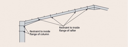
Where the compression flange of the rafter or column is not restrained by purlins or side rails, restraint can be provided at specific locations by column and rafter stays. Pertinent restraint locations are shown in the figure above right.
[top]Step 5: Frame stability
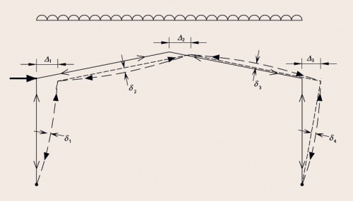

Once initial estimates of the member sizes have been made, sensitivity to second-order effects must be assessed. It is likely that second-order effects will need to be allowed for, either by amplifying the results of a first-order analysis, or by undertaking a second-order analysis. The figure shows the deflected shape caused by second-order effects in a portal frame under vertical loading.
When assessing frame stability it is important to correctly recognise the amount of fixity offered by the column bases (fixed bases are not fully fixed against rotation, neither are pinned bases fully free to rotate). Nominally pinned bases are modelled with a stiffness assumed to be a proportion of the column stiffness.
Typically the stiffness chosen is:
- 10% when assessing frame stability.
- 20% when calculating deflections at the Serviceability Limit State.
Refer to SCI P399 and SN045a-EN-EU.
[top]Step 6: Member verification
Once analysis of the frame has been performed the frame members must be verified. This includes verifying the member cross sectional resistance and member buckling resistance (member stability). A comprehensive treatise of member verification is presented in Section 8 in SCI P399. Critical locations for member verification are identified in SCI P400.
Verification of cross-sectional resistance comprises a number of checks, beginning with classification of member cross-sections. Classification includes the rafters, columns and the haunches. Classification of the haunch is more complex and reference should be made to SCI P397 Section 7.1.1 for more detailed information. This issue is also covered in the example in SCI P399 - see Section F3.5.1.

Cross-section resistance to bending, shear and compression is checked. Bending interaction with shear or compression is generally not critical. Although all column and rafter cross sections need to be verified, the likely key points for lateral torsional buckling are at the positions of maximum bending moment; in the column at the underside of the haunch, in the rafter at the sharp end of the haunch, in the rafter at the maximum sagging location adjacent to the apex.
The haunch (webs and flanges) must also be verified for bending, shear and axial compression for which a simple approach is provided in Section 8 in SCI P399.
Member buckling resistance
In portal frames, the columns and rafters are subject to combined axial force and bending. Member verification involves the determination of the flexural buckling resistance, the lateral-torsional buckling resistance and the resistance under combined axial force and bending. Both in-plane and out-of-plane buckling must be considered.
Members subject to axial compression and bending may be verified using expressions 6.61 and 6.62 according to BS EN 1993-1-1[6]. If the interaction coefficients needed for expressions 6.61 and 6.62 are selected from Annex B of BS EN 1993-1-1[6], the expressions may be considered to address in-plane and out-of-plane buckling respectively. Software tools are available to assist in these calculations.
However, for portal frames, as far as in-plane member verification is concerned, cross section checks are all that are required as second-order effects, and all imperfections, are allowed for in the global analysis. This conclusion is discussed in more detail in SCI P400.
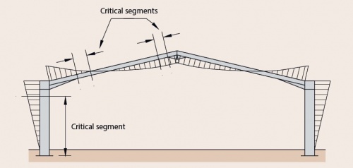
Out-of-plane stability checks differ for segments of members at and adjacent to plastic hinges, and segments of members which are elastic. In all cases, checks are undertaken between restraints. An additional restraint must be provided within a certain distance of all plastic hinges, according to Annex BB of BS EN1993-1-1[6]. Expression 6.62 should be used to verify segments of members for out-of-plane buckling between restraints.
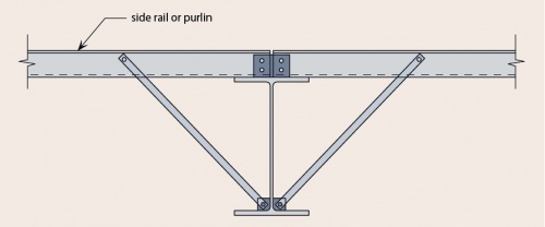

It is important for the designer to carefully consider the nature and location of all restraints, to cover all load combinations. The flange in compression, which needs restraining, will be different depending on the loading (gravity or uplift). The figure (right) shows how the inner flange of a rafter is restrained by connection to a purlin. Refer to Section 8 in SCI P399 for more detailed information on the design of restraints.
Once the restraints have been chosen it is essential that these details and their locations are communicated clearly to all concerned in the design of the building. A subsequent decision, for example, to accommodate a door thereby modifying a side rail location, can invalidate a portal frame design.
Out-of-plane member checks can be readily completed using resistances taken from the Blue Book (SCI P363). The axial resistance in the minor axis, Nb,z,Rd should be based on the distance between restraints. The bending resistance Mb,Rd should be based on the same length between restraints, accounting for the shape of the bending moment diagram using the C1 factor.
BS EN 1993-1-1[6], Section BB.3, has rules for stable lengths of tapered members (haunches), but only for lengths adjacent to plastic hinges. These may also be used, conservatively, for elastic haunches.
The steel sector has also developed a number of free software packages and spreadsheet tools to aid designers. In the case of member design, software tools are available to determine member compression and member bending resistances.
[top]Step 7: Connection design and detailing
The main connections requiring detailing and design are those at the eaves, apex and column bases.
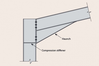

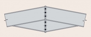
The major connections (or joints as they are called in the Eurocodes) in a portal frame are those at the eaves and the apex, which are both required to be moment-resisting. The eaves connection in particular is generally subject to a very large bending moment. Both the eaves and apex connections are likely to experience loading reversal in certain design situations and this can be an important design consideration for the connection. For economy, connections should be arranged to minimise any requirement for reinforcement (stiffeners) of the steel sections. This is generally achieved by:
- Making the haunch deeper (to increase the lever arm to the bolt rows).
- Extending the eaves connection above the top flange of the rafter (to allow an additional bolt row).
- Adding bolt rows within the depth of the connection.
- Selecting a stronger column section.
Guidance on the design of moment-resisting connections is given in SCI P398.

Bases, base plates and foundations

In the majority of cases, a nominally pinned base is provided, because of the difficulty and expense of providing a rigid base. A rigid base would involve a more expensive steel detail, but more significantly, the foundation would also have to resist the moment, which increases foundation costs significantly compared to a nominally pinned base.
The resistance of the base to horizontal forces can be achieved in several ways:
- Passive earth pressure on the side of the foundation.
- A tie cast into the floor slab, connected to the base of the column.
- A tie across the full width of the frame connecting both columns beneath or within the floor slab.
The most popular method of resisting horizontal forces is to use passive earth pressure. This has economic advantages in that the foundation size required to resist uplift is usually adequate to provide sufficient bearing resistance against the ground. It is important that the ground is properly compacted.
As an alternative, a tie cast into the floor slab, connected to the base of the column, can be a relatively cheap solution - see below.
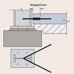

A tie across the full width of the frame connected to the column at each side is the most certain way of resisting horizontal forces. It is more expensive in terms of materials and labour and can be damaged by site activities. A full width tie may impede the erection of the structure, which generally will be undertaken from within the footprint of the building.
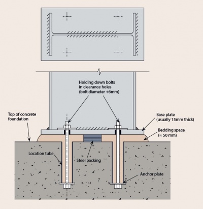
The steelwork contractor will usually be responsible for detailing the base plate and holding down bolts; commonly, another designer is responsible for the foundations. It should be made clear in the contract documentation where the responsibility lies for the interface, as special reinforcement spacing or details may be required. Best practice is to ensure that the holding down details are integrated with the foundation details.
Base plates will usually be grade S275 steel. Holding down bolts are usually Property Class 8.8. The diameter of the bolts will generally be determined by consideration of the uplift and shear forces applied to them, but will not normally be less than 20 mm.
[top]Step 8: Serviceability limit states (SLS)
Elastic analysis is used to determine the deflections of the frame at the serviceability limit state, and although recommended limits are presented below these deflections should be checked against client requirements (which will vary as a function of desired appearance, building use and cladding type).
| Type of cladding | Absolute deflection | Differential deflection relative to adjacent frame | |
|---|---|---|---|
| Side | Profiled metal sheeting | ≤ h / 100 | - |
| Fibre reinforced sheeting | ≤ h / 150 | - | |
| Brickwork | ≤ h / 300 | ≤ (h2 + b2)0.5 / 660 | |
| Hollow concrete blockwork | ≤ h / 200 | ≤ (h2 + b2)0.5 / 500 | |
| Precast concrete units | ≤ h / 200 | ≤ (h2 + b2)0.5 / 330 | |
| Roof | Profiled metal sheeting | - | ≤ b / 200 |
| Fibre reinforced sheeting | - | ≤ b / 250 | |
| Felted metal decking | - | ≤ b / 400 | |
| Type of roof cladding | Differential deflection relative to adjacent frame | |
|---|---|---|
| Profiled metal sheeting | ≤ b / 100 and ≤ (b2 + s2)0.5 / 125 | |
| Fibre reinforced sheeting | ≤ b / 100 and ≤ (b2 + s2)0.5 / 165 | |
| Felted metal decking | Supported on purlins | ≤ b / 100 and ≤ (b2 + s2)0.5 / 125 |
| Supported on rafter | ≤ b / 200 and ≤ (b2 + s2)0.5 / 250 | |
Notes:
The calculated deflections are those due to:
- wind actions
- imposed roof loads
- snow loads
- 80% of (wind actions and snow loads)
Some of the values may be more stringent than necessary
- 'h' is the height to eaves
- 'b' is the spacing of the portal frames
- 's' is the rafter slope length
In some cases, the frame is pre-set in a manner such that under the permanent actions the resulting deflections result in the frame having (for example) vertical columns. The degree of pre-set is partly a matter of calculation and partly a matter of experience – the steelwork contractor should be consulted if pre-setting the frame is being considered.
Some details of a portal framed building are particularly deflection sensitive:
- Limits on differential deflection between adjacent portal frames are necessary to prevent the fixings between the cladding sheets and the frame from becoming overstrained, resulting in tearing of the sheeting and possible water leakage.
- A sheeted and/or braced gable end is very stiff in its own plane and the deflections can be ignored. The calculated differential deflections between the end frame and the adjacent frame (at the ridge and at the eaves) can be very high.
- When brick or blockwork side walls are constructed such that they receive support from the steel frame, they should be detailed to allow them to deflect with the frame, and if this is not practical more onerous deflection limits should be applied to the frame.
- Where crane girders are supported directly from portal frames, the need to control deflections at the crane level is likely to result in stiffer sections for the frames.
- To ensure proper discharge of rainwater from a nominally flat roof, or from a very low-pitched roof (less than 1:20), deflections under permanent and variable actions should be checked to ensure that water does not pond.
[top]The design process for other components
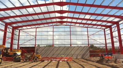

(Image courtesy of William Haley Engineering Ltd.)
The design process for other structural components of single-storey buildings includes the gable ends of the building, wall and roof bracing and secondary steelwork. Secondary steelwork includes purlins on the roof spanning between rafters, rails on the walls spanning between columns and eaves beams which are located at eaves and which span between adjacent portal frame bays.
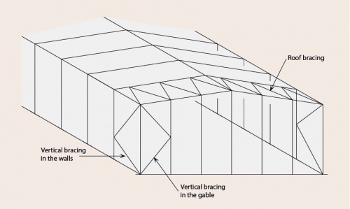
[top]Bracing
Bracing is required to resist longitudinal actions due to wind and cranes, and to provide restraint to members. It is common to use hollow sections as bracing members. Typical bracing in a portal frame building is shown.

[top]Vertical bracing
The primary functions of vertical bracing in the side walls of the frame are:
- To transmit the horizontal loads to the ground. The horizontal forces include forces from wind and cranes.
- To provide a rigid framework to which side rails and cladding may be attached so that the rails can in turn provide stability to the columns.
- To provide temporary stability during erection.
The bracing may be located:
- At one or both ends of the building.
- Within the length of the building.
- In each portion of the building between expansion joints (where these occur).
The bracing may take a number of forms, and different types of member may be used. One form of bracing system is shown below.
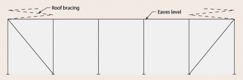

Where the side wall bracing is not in the same bay as the plan bracing in the roof, an eaves strut is essential to transmit the forces from the roof bracing into the wall bracing. An eaves strut is also required:
- To ensure the tops of the columns are adequately restrained in position.
- To assist during the construction of the structure.
- To stabilise the tops of the columns if a fire boundary condition exists.
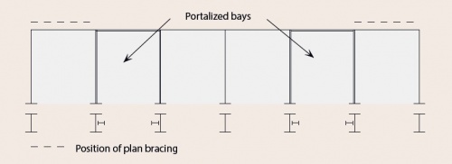
[top]Portalised bays
Where it is difficult or impossible to brace the frame vertically by conventional bracing, it is necessary to introduce moment-resisting frames in the elevations in one or more bays.
In addition to the general serviceability limit on deflection of h/300, where h is the height of the portalised bay, it is suggested that:
- The bending resistance of the portalised bay (not the main portal frame) is checked using an elastic frame analysis.
- Deflection under the equivalent horizontal forces is restricted to h/1000, where the equivalent horizontal forces are calculated based on the whole of the roof area.

[top]Bracing to restrain longitudinal loads from cranes
If a crane is directly supported by the frame, the longitudinal surge force will be eccentric to the column and will tend to cause the column to twist, unless additional restraint is provided. A horizontal truss at the level of the crane girder top flange or, for lighter cranes, a horizontal member on the inside face of the column flange tied into the vertical bracing may be adequate to provide the necessary restraint.
For large horizontal forces, additional bracing should be provided in the plane of the crane girder.
[top]Plan bracing
Plan bracing is located in the plane of the roof. The primary functions of the plan bracing are:
- To transmit wind forces from the gable posts to the vertical bracing in the walls.
- To transmit any frictional drag forces from wind on the roof to the vertical bracing.
- To provide stability during erection.
- To provide a stiff anchorage for the purlins which are used to restrain the rafters.
One form of plan bracing in the roof is shown.
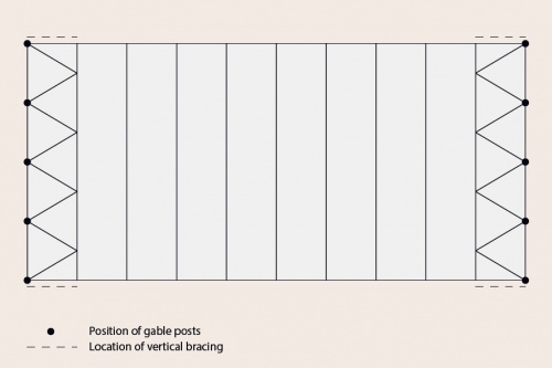

In order to transmit the wind forces efficiently, the plan bracing should connect to the top of the gable posts.
[top]Gable frames
The end frames of a portal frame building are generally called gable frames. Gable frames are typically one of two basic forms:
- A portal frame identical to the remainder of the structure. The gable columns are located in the plane of the frame but do not support the rafters. This form of gable is used for simplicity, or because there is the possibility of extending the structure in the future.
- A gable frame comprising gable posts with simply supported rafters between the posts. Gable frames of this form require bracing in the plane of the gable. The advantage of this form of gable is that the rafters and external columns are smaller than those in a portal frame.
A typical gable frame, in which the gable columns support the gable rafters, is shown below.

[top]Secondary steelwork
The secondary steelwork comprises a number of different elements:
- Eaves beams.
- Purlins.
- Side rails.
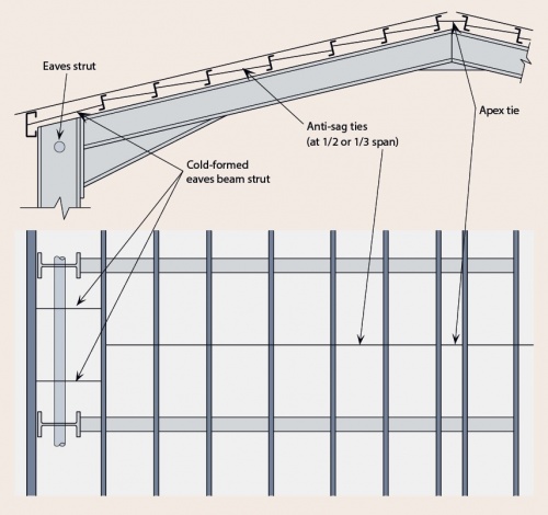
An eaves beam is a member (usually a cold rolled section) that supports the roof cladding, the wall cladding and any gutters. It is commonly located outside the outer flange of the column – in some cases at a significant distance. It should not be confused with an eaves strut, which carries longitudinal forces, provides positional restraint to the top of the portal columns and is generally a hot rolled member located within the depth of the column section.
Purlins are usually proprietary cold rolled thin gauge galvanized sections attached to the rafters using cleats. Suitably shaped sections have been developed and tested by manufacturers and the resulting design data are presented in terms of load/span tables or software. The designer should calculate the loading on the purlins, noting that the loads may act ‘up’ or ‘down’, and should use the manufacturer’s data to determine the size, type, and spacing of purlins. Particular care should be taken to understand the level of restraint to the purlins assumed in the tables – typically the purlins are assumed to be restrained by the cladding.
Anti-sag rods are small rods or angles that are bolted or clipped between the purlins. When used, they are commonly placed either at mid span or at third points along the purlin and serve the following functions:
- They provide restraint to the purlin against lateral torsional buckling under wind uplift conditions.
- They provide restraint to the purlins in the construction condition (before the installation of the cladding).
- They provide additional support to the down slope component of the applied loads.
- They help to maintain the alignment of the purlins.
A typical arrangement showing an anti-sag bar system is shown below.

Essentially, side rail design and detailing are very similar to that for purlins, and often the sections used are the same. In the case of side rails, the major loading to be resisted is that due to wind on the sides of the building. The self-weight deflection of the side rails due to bending about the weak axis is counteracted by the provision of anti-sag bars and tension wires at mid-span or third points.
[top]Cladding
There are a number of proprietary types of cladding on the market. These tend to fall into broad categories:
- Single-skin trapezoidal sheeting.
- Built-up double skin-system.
- ‘Standing seam’ sheeting.
- Insulated (composite or sandwich) panels.
- Typical proprietary cladding systems shown by category


Single-skin trapezoidal sheeting Single skin sheeting is widely used in agricultural and industrial structures where no thermal insulation is required. The sheeting is fixed directly to the purlins and side rails as shown. The cladding is generally made from 0.7 mm gauge pre coated steel with a 32 mm to 35 mm trapezoidal profile depth.
Built-up double skin-system This common type of cladding consists of a metal liner, a layer of insulation material, a spacer system and an outer metal sheet. The span of such systems is limited by the spanning capability of the cladding sheets, which is typically in the order of 2 m to 2.5 m depending on the applied loading. Built up cladding systems must, therefore, be supported by secondary steelwork (purlins or side rails). As the name suggests, these systems are built up from their constituent parts on site.
Standing seam sheeting ‘Standing seam’ (or ‘secret fix’) sheeting is a specially designed profile for the weather sheet, which incorporates a clipped joint between adjacent sheets. This eliminates the need for exposed fasteners and improves the weather tightness of the cladding system. Consequently, standing seam sheeting may be used on very low roof slopes (down to 1o compared to 4o for systems with exposed fasteners). Standing seam sheeting can be manufactured from steel or aluminium.
Insulated (composite or sandwich) panels Insulated roof and wall cladding panels consist of a rigid layer of insulation sandwiched between two metal skins. The result is a strong, stiff, lightweight panel with good spanning capabilities due to composite action in bending. These panels are commonly used on industrial buildings and retail ‘sheds’ in place of built up cladding. Insulated panels span between cold formed purlins or side rails, which in turn span between the primary frame members. Where secondary steelwork is not needed for restraint purposes, it is quite common for insulated wall cladding panels to span directly between the columns.
[top]Functions of the roof and wall cladding
The functions of the roof and wall cladding include some or all of the following:
- Separating the enclosed space from the external environment, to allow control of the internal environment, provide security etc.
- Transferring loads to the secondary steelwork.
- Restraining the secondary steelwork.
- Providing thermal insulation.
- Providing acoustic insulation.
- Preventing fire spread.
- Providing an airtight envelope.
- Providing ventilation to a building (ventilated or unventilated roofs and walls).
- Increasingly used for energy generation.
Thermal insulation
Increasing the building fabric insulation has often been the first approach taken when looking to reduce the thermal losses from a building. The designer needs to consider the implications of specifying a more highly insulated envelope, against the overall reductions in operational CO2 emissions which will be delivered. Recent studies, including Target Zero, have demonstrated that the cost effectiveness of reducing envelope U-values diminishes if they are reduced below current levels.
Thermal bridging
Thermal bridges occur where the envelope is penetrated by a material with a relatively high thermal conductivity and at interfaces between building elements where there is a discontinuity in the insulation. Thermal bridges result in local heat losses, consequently more energy is required to maintain the internal temperature of the building and lower internal surface temperatures can be found around the thermal bridge. Cold surface temperatures can cause condensation which may lead to mould growth.
Air tightness
Air tightness is a measure of the uncontrolled airflow into and out of the building. If a building is not designed well, or built without due consideration for sealing joints, it can lose a large amount of heat through uncontrolled ventilation. The air tightness of a building is central to the requirements of Part L of the Building Regulations and is likely to become even more important as architects strive to improve the thermal performance of the building envelope without significant increases in insulation thickness.
Acoustic insulation
There are two types of sound that should be considered in the acoustic design of buildings. These include airborne sound and impact sound. Airborne sound insulation is important for both walls and floors, whereas impact sound insulation is generally only relevant to floors.
Sound insulation for both routes is controlled by the following three characteristics mass, isolation and sealing.
It is important to be aware that the acoustic performance of a building can be sensitive to the quality of the workmanship.
Fire spread
In the UK, single storey buildings do not normally require fire resistance. Exceptions may occur where an element of structure provides support or stability to elements such as:
- A separating wall or a compartment wall.
- An external wall which must retain stability to prevent fire spread to adjacent buildings (i.e. a boundary condition).
- A support to a gallery or a roof which also forms the function of a floor (e.g. a car park or a means of escape).
Where structural fire resistance is required in a boundary condition, it has been widely accepted that it is necessary only for the affected wall and its supporting stanchions to have a fire resistant function. This requires that the steel should be fire protected and the cladding should have an insulation and integrity function.
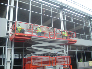
[top]Specification and installation of roof and wall cladding
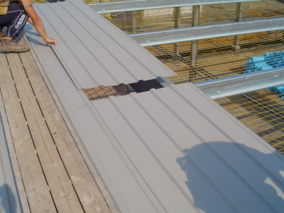

(Image courtesy of C A Roofing)
The ability of the building envelope to satisfy its functional requirements is dependent on its correct specification and installation and, equally as important, on its interaction with the other elements of the building envelope and structure.
The designer of a portal framed building should be particularly aware that different systems impose different levels of load on the frame and secondary steelwork during erection. This is relevant because purlins are normally sized on the basis that they will be restrained by the cladding, but during erection of the cladding this is not possible. For built-up systems construction loads are small, prior to the purlins being restrained by the liner trays. For insulated panels the full panel weight is applied during erection (liner, insulation, outer skin), and care is needed with the construction sequence. The sequence is discussed in detail in SCI P346.
Best practice guidance on the installation of purlins and side rails is available from the Metal Cladding and Roofing Manufacturers Association in Guidance document GD 24.
[top]Portal frame erection
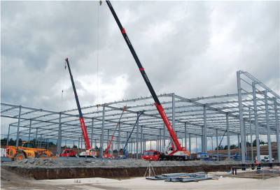

The erection of structural steelwork consists of the assembly of steel components into a frame on site. The processes involve lifting and placing components into position, then connecting them together. Generally this is achieved through bolting but sometimes site welding is used. The assembled frame needs to be aligned before bolting up is completed, and the structure handed over to the principal contractor.
Often the ability to complete these processes safely, quickly and economically is influenced significantly by early decisions made during design long before erection commences. It is important that designers clearly understand the impact that their decisions can have; ‘buildability’ is a valid design objective. Detailed advice is given in SCI P178 Design for Construction.
Good site co-ordination will facilitate a smooth running project. Adequate access is required by the steelwork contractor for steel transportation, unloading and erection, both on the site as well as on surrounding or adjacent access roads. The provision of well-prepared level ground that is able to take the requisite wheel loads is essential. Use of the BCSA Safe Site Handover Certificate will assist in meeting these requirements, thus reducing the risk of accidents and delays due to poor and unsafe site conditions.
[top]References
- ↑ Structural design – the engineer’s role, September 2011, The Institution of Structural Engineers
- ↑ BS EN 1991-1-1: 2002 Eurocode 1. Actions on structures. General actions. Densities, self-weight, imposed loads for buildings, BSI
- ↑ BS EN 1991-1-3:2003+A1:2015 Eurocode 1. Actions on structures. General actions. Snow loads, BSI
- ↑ BS EN 1991-1-4:2005+A1:2010 Eurocode 1. Actions on structures. General actions. Wind actions, BSI
- ↑ BS EN 1990:2002:+A1:2005, Eurocode - Basis of structural design, BSI
- ↑ 6.0 6.1 6.2 6.3 6.4 BS EN 1993-1-1:2005+A1:2014, Eurocode 3: Design of steel structures. General rules and rules for buildings, BSI
[top]Further reading
- Steel Buildings, BCSA No. 35/03, Chapter 3, Single Storey Buildings
- Steel Buildings, BCSA No. 35/03, Chapter 22, Building Envelope
- Steel Designers' Manual 7th Edition. Editors B Davison & G W Owens. The Steel Construction Institute 2012, Chapter 4, Single Storey Buildings
[top]Resources
- SCI P178 Design for Construction
- SCI P347 Single Storey Buildings – Best practice guidance for developers, owners, designers & constructors
- EP37 Best Practice in Steel Construction – Industrial Buildings, Guidance for architects, designers & constructors
- SCI P313 Single Storey Steel Framed Buildings in Fire Boundary Conditions
- SCI P346, Best Practice for the Specification and Installation of Metal Cladding and Secondary Steelwork
- SCI P363 Steel Building Design: Design Data, 2013
A web-based interactive version of the 'Blue Book', is also available. - SCI P397 Elastic Design of Single-span Steel Portal Frame Buildings to Eurocode 3, 2013
- SCI P398 Joints in Steel Construction: Moment-resisting Joints to Eurocode 3, 2013
- SCI P399 Design of portal frame buildings to Eurocode 3, 2015
- SCI P400 Interim report: Design of portal frames to Eurocode 3: An overview for UK designers, 2013
- SN045a-EN-EU Access Steel. NCCI: Column base stiffness for global analysis
- Target Zero: Guidance on the design and construction of sustainable, low carbon warehouse buildings, Tata Steel and BCSA
- Scheme development: Selection of the external wall envelope system for single storey buildings, SS019a-EN-EU
- Scheme development: Details for portal frames using rolled sections, SS051a-EN-EU
- Scheme Development: Design of portal frames using fabricated welded sections, SS052a-EN-EU
- Scheme development: Selection of the external roof envelope system for single storey buildings, SS018a-EN-EU
- Scheme development: Overview of structural systems for single-storey buildings, SS048a-EN-EU
- Steel Buildings in Europe - Single storey buildings:
- Part 1: Architect’s guide
- Part 2: Concept design
- Part 3: Actions
- Part 4: Detailed design of portal frames
- Part 5: Detailed design of trusses
- Part 6: Detailed design of built up columns
- Part 7: Fire engineering
- Part 8: Building envelope
- Part 9: Introduction to computer software
- Part 10: Model construction specification
- Part 11: Moment connections
- Safe Site Handover Certificate and Checklist, 2022, BCSA
- Guidance document GD 24 – Installation of purlins and side rails, MCRMA, January 2016
[top]See Also
- Single storey industrial buildings
- Portal frames
- Design codes and standards
- Modelling and analysis
- Allowing for the effects of deformed frame geometry
- Member design
- Concept design
- Moment resisting connections
- Building envelopes
- Thermal performance
- Acoustics
- Single storey buildings in fire boundary conditions
- Fabrication
- Construction
- Sustainability
- Cost of structural steelwork
- Cost planning - Industrial buildings
- Health and safety