


Portal frames
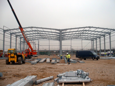
Portal frames are generally low-rise structures, comprising columns and horizontal or pitched rafters, connected by moment-resisting connections. Resistance to lateral and vertical actions is provided by the rigidity of the connections and the bending stiffness of the members, which is increased by a suitable haunch or deepening of the rafter sections. This form of continuous frame structure is stable in its plane and provides a clear span that is unobstructed by bracing. Portal frames are very common, in fact 50% of constructional steel used in the UK is in portal frame construction. They are very efficient for enclosing large volumes, therefore they are often used for industrial, storage, retail and commercial applications as well as for agricultural purposes. This article describes the anatomy and various types of portal frame and key design considerations.

[top]Anatomy of a typical portal frame
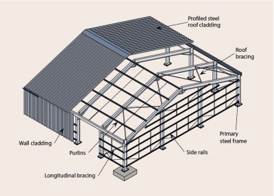

A portal frame building comprises a series of transverse frames braced longitudinally. The primary steelwork consists of columns and rafters, which form portal frames, and bracing. The end frame (gable frame) can be either a portal frame or a braced arrangement of columns and rafters.
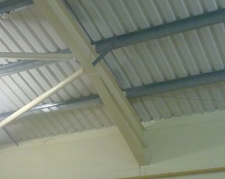
The light gauge secondary steelwork consists of side rails for walls and purlins for the roof. The secondary steelwork supports the building envelope, but also plays an important role in restraining the primary steelwork.
The roof and wall cladding separate the enclosed space from the external environment as well as providing thermal and acoustic insulation. The structural role of the cladding is to transfer loads to secondary steelwork and also to restrain the flange of the purlin or rail to which it is attached.

Portal framed structures - overview
[top]Types of portal frames
Many different forms of portal frames may be constructed. Frame types described below give an overview of types of portal construction with typical features illustrated. This information only provides typical details and is not meant to dictate any limits on the use of any particular structural form.

|
Pitched roof symmetric portal frame
Generally fabricated from UB sections with a substantial eaves haunch section, which may be cut from a rolled section or fabricated from plate. 25 to 35 m are the most efficient spans. |

Pitched roof symmetric portal frame |

|
Portal frame with internal mezzanine floor
Office accommodation is often provided within a portal frame structure using a partial width mezzanine floor.
|

Portal frame with internal mezzanine floor |

|
Crane portal frame with column brackets
Where a travelling crane of relatively low capacity (up to say 20 tonnes) is required, brackets can be fixed to the columns to support the crane rails. Use of a tie member or rigid column bases may be necessary to reduce the eaves deflection.
|
|

|
Tied portal frame
In a tied portal frame the horizontal movement of the eaves and the bending moments in the columns and rafters are reduced. A tie may be useful to limit spread in a crane-supporting structure.
|
|

|
Mono-pitch portal frame
A mono pitch portal frame is usually chosen for small spans or because of its proximity to other buildings. It is a simple variation of the pitched roof portal frame, and tends to be used for smaller buildings (up to 15 m span). |
|

|
Propped portal frame
Where the span of a portal frame is large and there is no requirement to provide a clear span, a propped portal frame can be used to reduce the rafter size and also the horizontal shear at the foundations. |

Propped portal frame |

|
Mansard portal frame
A mansard portal frame may be used where a large clear height at mid-span is required but the eaves height of the building has to be minimised. |
|

|
Curved rafter portal frame
Portal frames may be constructed using curved rafters, mainly for architectural reasons. Because of transport limitations rafters longer than 20 m may require splices, which should be carefully detailed for architectural reasons.
|
|

|
Cellular beam portal frame
Rafters may be fabricated from cellular beams for aesthetic reasons or when providing long spans. Where transport limitations impose requirement for splices, they should be carefully detailed, to preserve the architectural features.
|

Cellular beam portal frame |
[top]Design considerations
In the design and construction of any structure, a large number of inter-related design requirements should be considered at each stage in the design process. The following discussion of the design process and its constituent parts is intended to give the designer an understanding of the inter-relationship of the various elements of the structure with its final construction, so that the decisions required at each stage can be made with an understanding of their implications.
[top]Choice of material and section
Steel sections used in portal frame structures are usually specified in grade S355 steel.
In plastically designed portal frames, Class 1 plastic sections must be used at hinge positions that rotate, Class 2 compact sections can be used elsewhere.
[top]Frame dimensions
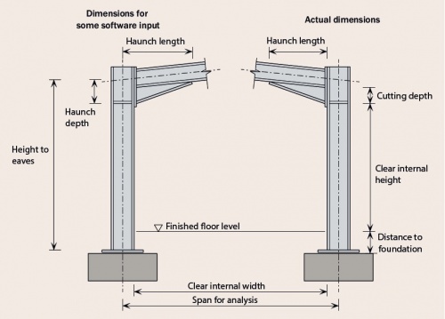

A critical decision at the conceptual design stage is the overall height and width of the frame, to give adequate clear internal dimensions and adequate clearance for the internal functions of the building.
[top]Clear span and height
The clear span and height required by the client are key to determining the dimensions to be used in the design, and should be established early in the design process. The client requirement is likely to be the clear distance between the flanges of the two columns – the span will therefore be larger, by the section depth. Any requirement for brickwork or blockwork around the columns should be established as this may affect the design span.
Where a clear internal height is specified, this will usually be measured from the finished floor level to the underside of the haunch or suspended ceiling if present.
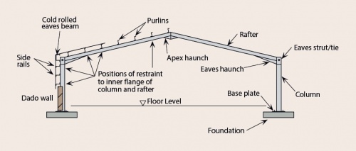
[top]Main frame
The main (portal) frames are generally fabricated from UB sections with a substantial eaves haunch section, which may be cut from a rolled section or fabricated from plate. A typical frame is characterised by:
- A span between 15 and 50 m
- A clear height (from the top of the floor to the underside of the haunch) between 8 and 18 m
- A roof pitch between 5° and 10° (6° is commonly adopted)
- A frame spacing between 6 and 8 m
- Haunches in the rafters at the eaves and apex
- A stiffness ratio between the column and rafter section of approximately 1.5
- Light gauge purlins and side rails
- Light gauge diagonal ties from some purlins and side rails to restrain the inside flange of the frame at certain locations.
[top]Haunch dimensions

The use of a haunch at the eaves reduces the required depth of rafter by increasing the moment resistance of the member where the applied moments are highest. The haunch also adds stiffness to the frame, reducing deflections, and facilitates an efficient bolted moment connection.
The eaves haunch is typically cut from the same size rolled section as the rafter, or one slightly larger, and is welded to the underside of the rafter. The length of the eaves haunch is generally 10% of the frame span. The haunch length generally means that the hogging moment at the end of the haunch is approximately equal to the largest sagging moment close to the apex. The depth from the rafter axis to the underside of the haunch is approximately 2% of the span.
The apex haunch may be cut from a rolled section – often from the same size as the rafter, or fabricated from plate. The apex haunch is not usually modelled in the frame analysis and is only used to facilitate a bolted connection.
[top]Positions of restraints

During initial design the rafter members are normally selected according to their cross sectional resistance to bending moment and axial force. In later design stages stability against buckling needs to be verified and restraints positioned judiciously.
The buckling resistance is likely to be more significant in the selection of a column size, as there is usually less freedom to position rails to suit the design requirements; rail position may be dictated by doors or windows in the elevation.
If introducing intermediate lateral restraints to the column is not possible, the buckling resistance will determine the initial section size selection. It is therefore essential to recognise at this early stage if the side rails may be used to provide restraint to the columns. Only continuous side rails are effective in providing restraint. Side rails interrupted by (for example) roller shutter doors, cannot be relied on as providing adequate restraint.
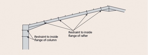
Where the compression flange of the rafter or column is not restrained by purlins and side rails, restraint can be provided at specified locations by column and rafter stays to the inside flange.
[top]Actions
Advice on actions can be found in BS EN 1991[1], and on the combinations of actions in BS EN 1990[2]. It is important to refer to the UK National Annex for the relevant Eurocode part for the structures to be constructed in the UK.
[top]Permanent actions
Permanent actions are the self weight of the structure, secondary steelwork and cladding. Where possible, unit weights of materials should be obtained from manufacturers’ data. Where information is not available, these may be determined from the data in BS EN 1991-1-1[3].
[top]Service loads
Service loads will vary greatly depending on the use of the building. In portal frames heavy point loads may occur from suspended walkways, air handling units etc. It is necessary to consider carefully where additional provision is needed, as particular items of plant must be treated individually.
Depending on the use of the building and whether sprinklers are required, it is normal to assume a service loading of 0.1–0.25 kN/m2 on plan over the whole roof area.
[top]Variable actions
[top]Imposed roof loads
| Roof slope, α | qk (kN/m²) |
|---|---|
| α < 30° | 0.6 |
| 30° < α < 60° | 0.6[60 - α)/30] |
| α > 60° | 0 |
Imposed loads on roofs are given in the UK NA to BS EN 1991-1-1[4], and depend on the roof slope. A point load, Qk is given, which is used for local checking of roof materials and fixings, and a uniformly distributed load, qk, to be applied vertically. The uniform loading for roofs not accessible except for normal maintenance and repair is given in the table on the right.
It should be noted that imposed loads on roofs should not be combined with either snow or wind.
[top]Snow loads
Snow loads may sometimes be the dominant gravity loading. Their value should be determined from BS EN 1991-1-3[5] and its UK National Annex[6] – the determination of snow loads is described in Chapter 3 of the Steel Designers’ Manual.
Any drift condition must be allowed for not only in the design of the frame itself, but also in the design of the purlins that support the roof cladding. The intensity of loading at the position of maximum drift often exceeds the basic minimum uniform snow load. The calculation of drift loading and associated purlin design has been made easier by the major purlin manufacturers, most of whom offer free software to facilitate rapid design.
[top]Wind actions
Wind actions in the UK should be determined using BS EN 1991-1-4[7] and its UK National Annex[8]. This Eurocode gives much scope for national adjustment and therefore its annex is a substantial document.
Wind actions are inherently complex and likely to influence the final design of most buildings. The designer needs to make a careful choice between a fully rigorous, complex assessment of wind actions and the use of simplifications which ease the design process but make the loads more conservative. Free software for establishing wind pressures is available from purlin manufacturers.
For more advice refer to Chapter 3 of the Steel Designers’ Manual and SCI P394.
[top]Crane actions
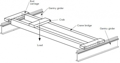

The most common form of craneage is the overhead type running on beams supported by the columns. The beams are carried on cantilever brackets or, in heavier cases, by providing dual columns.
In addition to the self weight of the cranes and their loads, the effects of acceleration and deceleration have to be considered. For simple cranes, this is by a quasi-static approach with amplified loads
For heavy, high-speed or multiple cranes the allowances should be specially calculated with reference to the manufacturer.
The frequent occurrence of crane loads may require a fatigue assessment of the affected parts of the structure.
[top]Accidental actions
The common design situations which are treated as accidental design situations are:
- Drifted snow, determined using Annex B of BS EN 1991-1-3[5]
- The opening of a dominant opening which was assumed to be shut at ULS
Each project should be individually assessed whether any other accidental actions are likely to act on the structure.
[top]Robustness
Robustness requirements are designed to ensure that any structural collapse is not disproportionate to the cause. BS EN 1990[2] sets the requirement to design and construct robust buildings in order to avoid disproportionate collapse under accidental design situations. BS EN 1991-1-7[9] gives details of how this requirement should be met.
For many portal frame structures no special provisions are needed to satisfy robustness requirements set by the Eurocode.
For more information on robustness refer to SCI P391.
[top]Fire
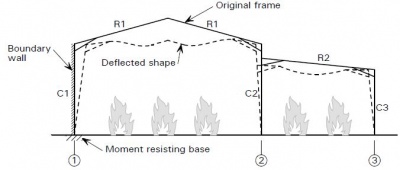

In the United Kingdom, structural steel in single storey buildings does not normally require fire resistance. The most common situation in which it is required to fire protect the structural steelwork is where prevention of fire spread to adjacent buildings, known as a boundary condition, is required. There are a small number of other, rare, instances, for example when demanded by an insurance provider, where structural fire protection may be required.
When a portal frame is close to the boundary, there are several requirements aimed at stopping fire spread by keeping the boundary intact:
- The use of fire resistant cladding
- Application of fire protection of the steel up to the underside of the haunch
- The provision of a moment resisting base (as it is assumed that in the fire condition rafters go into catenary)
Comprehensive advice is available in SCI P313.
[top]Combinations of actions
BS EN 1990[2] gives rules for establishing combinations of actions, with the values of relevant factors given in the UK National Annex[10]. BS EN 1990[2] covers both ultimate limit state (ULS) and serviceability limit state (SLS), although for the SLS, onward reference is made to the material codes (for example BS EN 1993-1-1[11] for steelwork) to identify which expression should be used and what SLS limits should be observed.
All combinations of actions that can occur together should be considered, however if certain actions cannot be applied simultaneously, they should not be combined.
Guidance on the application of Eurocode rules on combinations of actions can be found in SCI P362 and, specifically for portal frames, in SCI P399.
[top]Frame analysis at ULS
At the ultimate limit state (ULS), the methods of frame analysis fall broadly into two types: elastic analysis and plastic analysis.
[top]Plastic analysis
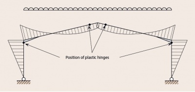

The term plastic analysis is used to cover both rigid-plastic and elastic-plastic analysis. Plastic analysis commonly results in a more economical frame because it allows relatively large redistribution of bending moments throughout the frame, due to plastic hinge rotations. These plastic hinge rotations occur at sections where the bending moment reaches the plastic moment or resistance of the cross-section at loads below the full ULS loading.
The rotations are normally considered to be localised at “plastic hinges” and allow the capacity of under-utilised parts of the frame to be mobilised. For this reason members where plastic hinges may occur need to be Class 1 sections, which are capable of accommodating rotations.
The figure shows typical positions where plastic hinges form in a portal frame. Two hinges lead to a collapse, but in the illustrated example, due to symmetry, designers need to consider all possible hinge locations.
[top]Elastic analysis
A typical bending moment diagram resulting from an elastic analysis of a frame with pinned bases is shown the figure below. In this case, the maximum moment (at the eaves) is higher than that calculated from a plastic analysis. Both the column and haunch have to be designed for these large bending moments.
Where deflections (SLS) govern design, there may be no advantage in using plastic analysis for the ULS. If stiffer sections are selected in order to control deflections, it is quite possible that no plastic hinges form and the frame remains elastic at ULS.
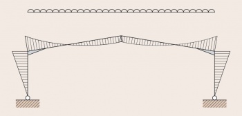
Bending moment diagram resulting from the elastic analysis of a symmetrical portal frame under symmetrical loading
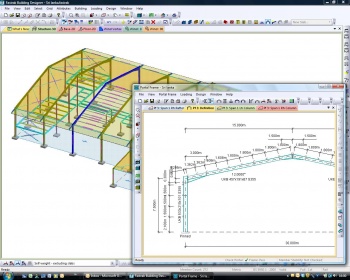
Portal frame analysis software
(Fastrak model courtesy of Trimble)


[top]In-plane frame stability
When any frame is loaded, it deflects and its shape under load is different from the un-deformed shape. The deflection has a number of effects:
- The vertical loads are eccentric to the bases, which leads to further deflection
- The apex drops, reducing the arching action
- Applied moments curve members; Axial compression in curved members causes increased curvature (which may be perceived as a reduced stiffness.)
Taken together, these effects mean that a frame is less stable (nearer collapse) than a first-order analysis suggests. The objective of assessing frame stability is to determine if the difference is significant.
[top]Second order effects
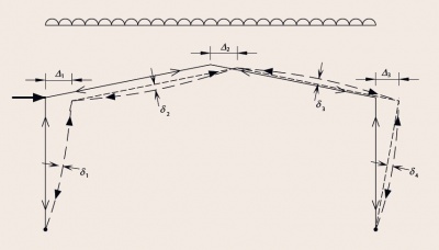

The geometrical effects described above are second-order effects and should not be confused with non linear behaviour of materials. As shown in the figure there are two categories of second-order effects:
- Effects of displacements of the intersections of members, usually called P-Δ effects. BS EN 1993-1-1[11] describes this as the effect of deformed geometry.
- Effects of deflections within the length of members, usually called P-δ effects.
Second-order analysis is the term used to describe analysis methods in which the effects of increasing deflection under increasing load is considered explicitly in the solution, so that the results include the P-δ and P-Δ effects.
[top]First-order and second-order analysis
For either plastic analysis of frames, or elastic analysis of frames, the choice of first-order analysis or second-order analysis depends on the in plane flexibility of the frame, characterised by the calculation of the αcr factor.
[top]Calculation of αcr
The effects of the deformed geometry (P-Δ effects) are assessed in BS EN 1993–1–1[11] by calculating the factor αcr, defined as:
![]()
where:
Fcr is the elastic critical buckling load for global instability mode, based on initial elastic stiffnesses
FEd is the design load on the structure.
αcr may be found using software or using an approximation (expression 5.2 from BS EN 1993-1-1[11]) as long as the frame meets certain geometric limits and the axial force in the rafter is not ‘significant’. Rules are given in the Eurocode to identify when the axial force is significant. When the frame falls outside the specified limits, as is the case for very many orthodox frames, the simplified expression cannot be used. In these circumstances, an alternative expression may be used to calculate an approximate value of αcr, referred to as αcr,est. Further details are given in SCI P399.
[top]Sensitivity to effects of the deformed geometry
The limitations to the use of first-order analysis are defined in BS EN 1993–1–1[11], Section 5.2.1 (3) and the UK National Annex[12] Section NA.2.9 as:
For elastic analysis: αcr ≥ 10
For plastic analysis:
- αcr ≥ 5 for combinations with gravity loading with frame imperfections,
provided that:
a) the span, L, does not exceed 5 times the mean height of the columns
b) hr (the height of the apex above the tops of the columns) satisfies the criterion: (hr/ sa)2 + (hr/ sb)2 ≤ 0.5 in which sa and sb are the horizontal distances from the apex to the columns. For a symmetrical frame this expression simplifies to hr ≤ 0.25L.
- αcr ≥ 10 for combinations with gravity loading with frame imperfections for clad structures provided that the stiffening effects of masonry infill wall panels or diaphragms of profiled steel sheeting are not taken into account
[top]Design
Once the analysis has been completed, allowing for second-order effects if necessary, the frame members must be verified.
Both the cross-sectional resistance and the buckling resistance of the members must be verified. In-plane buckling of members (using expression 6.61 of BS EN 1993-1-1[11]) need not be verified as the global analysis is considered to account for all significant in-plane effects. SCI P399 identifies the likely critical zones for member verification. SCI P397 contains numerical examples of member verifications.
[top]Cross-section resistance
Member bending, axial and shear resistances must be verified. If the shear or axial force is high, the bending resistance is reduced so combined shear force and bending and axial force and bending resistances need to be verified. In typical portal frames neither the shear force nor the axial load is sufficiently high to reduce the bending resistance. When the portal frame forms the chord of the bracing system in the plane of the roof, the axial load in the rafter may be significant, and this combination of actions should be verified.
Although all cross-sections need to be verified, the likely key points are at the positions of maximum bending moment:
- In the column at the underside of the haunch
- In the rafter at the sharp end of the haunch
- In the rafter at the maximum sagging location adjacent to the apex.
[top]Member stability
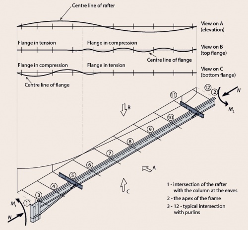

The figure shows a diagrammatic representation of the issues that need to be addressed when considering the stability of a member within a portal frame, in this example a rafter between the eaves and apex. The following points should be noted:
- Purlins provide intermediate lateral restraint to one flange. Depending on the bending moment diagram this may be either the tension or compression flange
- Restraints to the inside flange can be provided at purlin positions, producing a torsional restraint at that location.
In-plane, no member buckling checks are required, as the global analysis has accounted for all significant in-plane effects. The analysis has accounted for any significant second-order effects, and frame imperfections are usually accounted for by including the equivalent horizontal force in the analysis. The effects of in-plane member imperfections are small enough to be ignored. Out of plane, the combined effects of axial load and bending are checked using BS EN 1993-1-1[11] equation 6.62:

Because there are no minor axis moments in a portal frame rafter, Expression 6.62 simplifies to:

[top]Rafter design and stability
In the plane of the frame rafters are subject to high bending moments, which vary from a maximum ‘hogging’ moment at the junction with the column to a minimum sagging moment close to the apex. Compression is introduced in the rafters due to actions applied to the frame. The rafters are not subject to any minor axis moments. Optimum design of portal frame rafters is generally achieved by use of:
- A cross section with a high ratio of Iyy to Izz that complies with the requirements of Class 1 or 2 under combined major axis bending and axial compression.
- A haunch that extends from the column for approximately 10% of the frame span. This will generally mean that the maximum hogging and sagging moments in the plain rafter length are of similar magnitude.
[top]Out-of-plane stability
Purlins attached to the top flange of the rafter provide stability to the member in a number of ways:
- Direct lateral restraint, when the outer flange is in compression
- Intermediate lateral restraint to the tension flange between torsional restraints, when the outer flange is in tension
- Torsional and lateral restraint to the rafter when the purlin is attached to the tension flange and used in conjunction with rafter stays to the compression flange.
Initially, the out-of-plane checks are completed to ensure that the restraints are located at appropriate positions and spacing.
[top]Gravity combination of actions
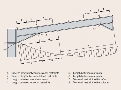

The figure shows a typical moment distribution for the gravity combination of actions, typical purlin and restraint positions as well as stability zones, which are referred to further.
Purlins are generally placed at up to 1.8 m spacing but this spacing may need to be reduced in the high moment regions near the eaves.
In Zone A, the bottom flange of the haunch is in compression. The stability checks are complicated by the variation in geometry along the haunch. The bottom flange is partially or wholly in compression over the length of Zone B. In Zone C, the purlins provide lateral restraint to the top (compression) flange.
The selection of the appropriate check depends on the presence of a plastic hinge, the shape of the bending moment diagram and the geometry of the section (three flanges or two flanges). The objective of the checks is to provide sufficient restraints to ensure the rafter is stable out-of-plane.
Guidance on details of the out-of plane stability verification can be found in SCI P399.
[top]The uplift condition
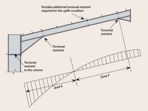

In the uplift condition the top flange of the haunch will be in compression and will be restrained by the purlins. The moments and axial forces are smaller than those in the gravity load combination. As the haunch is stable in the gravity combination of actions, it will certainly be so in the uplift condition, being restrained at least as well, and under reduced loads
In Zone F, the purlins will not restrain the bottom flange, which is in compression.
The rafter must be verified between torsional restraints. A torsional restraint will generally be provided adjacent to the apex. The rafter may be stable between this point and the virtual restraint at the point of contraflexure, as the moments are generally modest in the uplift combination. If the rafter is not stable over this length, additional torsional restraints should be introduced, and each length of the rafter verified.
[top]In plane stability
No in-plane checks of rafters are required, as all significant in-plane effects have been accounted for in the global analysis.
[top]Column design and stability

The most heavily loaded region of the rafter is reinforced by the haunch. By contrast, the column is subject to a similar bending moment at the underside of the haunch, but without any additional strengthening.
The optimum design for most columns is usually achieved by the use of:
- A cross section with a high ratio of Iyy to Izz that complies with Class 1 or Class 2 under combined major axis bending and axial compression
- A plastic section modulus that is approximately 50% greater than that of the rafter.
The column size will generally be determined at the preliminary design stage on the basis of the required bending and compression resistances.
Whether the frame is designed plastically or elastically, a torsional restraint should always be provided at the underside of the haunch. This may be from a side rail positioned at that level, or by some other means. Additional torsional restraints may be required between the underside of the haunch and the column base because the side rails are attached to the (outer) tension flange; unless restraints are provided the inner compression flange is unrestrained. A side rail that is not continuous (for example, interrupted by industrial doors) cannot be relied upon to provide adequate restraint. The column section may need to be increased if intermediate restraints to the compression flange cannot be provided.
The presence of a plastic hinge will depend on loading, geometry and choice of column and rafter sections. In a similar way to the rafter, out-of-plane stability must be verified.
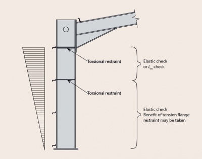
[top]Out-of-plane stability
If there is a plastic hinge at the underside of the haunch (which must be torsionally restrained), the distance to the adjacent torsional restraint must be less than the limiting distance Ls as given by BS EN 1993-1-1[11] Clause BB.3.1.2.
It may be possible to demonstrate that a torsional restraint is not required at the next side rail below the hinge, but may be provided at some greater distance. In this case there will be intermediate lateral restraints between the torsional restraints, which must be provided at a distance not less than Lm from the plastic hinge, as given in clause BB.3.1.1
If the stability between torsional restraints cannot be verified, it may be necessary to introduce additional torsional restraints. If it is not possible to provide additional intermediate restraints, the size of the member must be increased.
In all cases, a lateral restraint must be provided within Lm of a plastic hinge.
When the frame is subject to uplift, the column moment will reverse. The bending moments will generally be significantly smaller than those under gravity loading combinations, and the column is likely to remain elastic
[top]In plane stability
No in-plane checks of columns are required, as all significant in-plane effects have been accounted for in the global analysis.
[top]Bracing
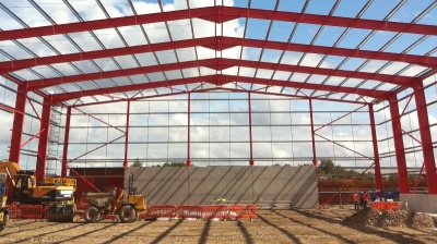

(Image courtesy of William Haley Engineering Ltd.)
Bracing is required to resist longitudinal actions due to wind and cranes, and to provide restraint to members.
It is common to use hollow sections as bracing members.
Bracing arrangement in a typical portal frame
[top]Vertical bracing
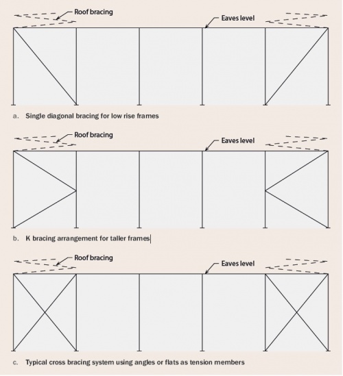

The primary functions of vertical bracing in the side walls of the frame are:
- To transmit the horizontal loads to the ground. The horizontal forces include forces from wind and cranes
- To provide a rigid framework to which side rails and cladding may be attached so that the rails can in turn provide stability to the columns
- To provide temporary stability during erection.
The bracing may be located:
- At one or both ends of the building
- Within the length of the building
- In each portion between expansion joints (where these occur).
Where the side wall bracing is not in the same bay as the plan bracing in the roof, an eaves strut is essential to transmit the forces from the roof bracing into the wall bracing. An eaves strut is also required:
- To ensure the tops of the columns are adequately restrained in position
- To assist in during the construction of the structure
- To stabilise the tops of the columns if a fire boundary condition exists
[top]Portalised bays
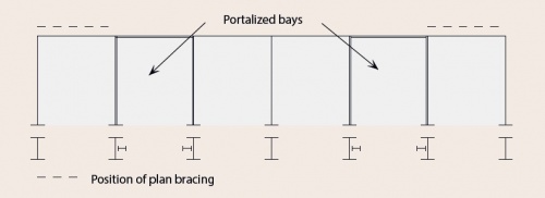

Where it is difficult or impossible to brace the frame vertically by conventional bracing, it is necessary to introduce moment-resisting frames in the elevations in one or more bays.
In addition to the general serviceability limit on deflection of h/300, where h is the height of the portalised bay it is suggested that:
- The bending resistance of the portalised bay (not the main portal frame) is checked using an elastic frame analysis
- Deflection under the equivalent horizontal forces is restricted to h/1000, where the equivalent horizontal forces are calculated based on the whole of the roof area.
[top]Bracing to restrain longitudinal loads from cranes
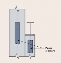

If a crane is directly supported by the frame, the longitudinal surge force will be eccentric to the column and will tend to cause the column to twist, unless additional restraint is provided. A horizontal truss at the level of the crane girder top flange or, for lighter cranes, a horizontal member on the inside face of the column flange tied into the vertical bracing may be adequate to provide the necessary restraint.
For large horizontal forces, additional bracing should be provided in the plane of the crane girder.
[top]Plan bracing
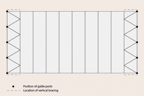

Plan bracing is located in the plane of the roof. The primary functions of the plan bracing are:
- To transmit wind forces from the gable posts to the vertical bracing in the walls
- To transmit any frictional drag forces from wind on the roof to the vertical bracing
- To provide stability during erection
- To provide a stiff anchorage for the purlins which are used to restrain the rafters.
In order to transmit the wind forces efficiently, the plan bracing should connect to the top of the gable posts.
[top]Restraint to inner flanges
Restraint to the inner flanges of rafters or columns is often most conveniently formed by diagonal struts from the purlins or sheeting rails to small plates welded to the inner flange and web. Pressed steel flat ties are commonly used. Where restraint is only possible from one side, the restraint must be able to carry compression. In these locations angle sections of minimum size 40 × 40 mm must be used. The stay and its connections should be designed to resist a force equal to 2.5% of the maximum force in the column or rafter compression flange between adjacent restraints.
[top]Connections
The major connections in a portal frame are the eaves and apex connections, which are both moment-resisting. The eaves connection in particular must generally carry a very large bending moment. Both the eaves and apex connections are likely to experience reversal in certain combinations of actions and this can be an important design case. For economy, connections should be arranged to minimise any requirement for additional reinforcement (commonly called stiffeners). This is generally achieved by:
- Making the haunch deeper (increasing the lever arms)
- Extending the eaves connection above the top flange of the rafter (an additional bolt row)
- Adding bolt rows
- Selecting a stronger column section.
The design of moment resisting connections is covered in detail in SCI P398.
- Typical portal frame connections
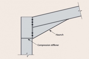
Eaves connection
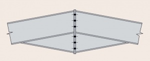
Apex connection


Haunched connections
[top]Column bases
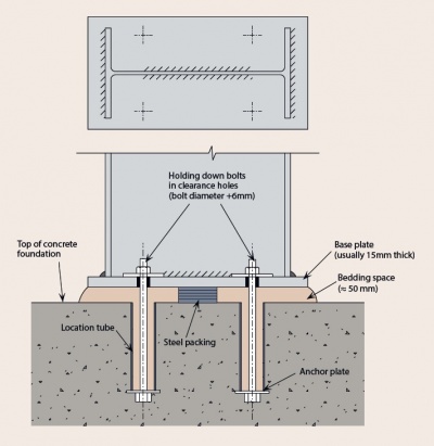

In the majority of cases, a nominally pinned base is provided, because of the difficulty and expense of providing a rigid base. A rigid base will involve a more expensive base detail, but more significantly, the foundation must also resist the moment, which increases costs significantly compared to a nominally pinned base.
If a column base is nominally pinned, it is recommended that the base be modelled as perfectly pinned when using elastic global analysis to calculate the moments and forces in the frame under ULS loading.
The stiffness of a nominally pinned base may be assumed to be equal to the following proportion of the column stiffness:
- 10% when assessing frame stability
- 20% when calculating deflections under serviceability loads.
[top]References
- ↑ BS EN 1991, Eurocode 1: Actions on structures (Various Parts), BSI
- ↑ 2.0 2.1 2.2 2.3 BS EN 1990:2002+A1:2005, Eurocode - Basis of structural design, BSI
- ↑ BS EN 1991-1-1: 2002 Eurocode 1: Actions on structures. General actions. Densities, self-weight, imposed loads for buildings , BSI
- ↑ NA to BS EN 1991-1-1: 2002, UK National Annex to Eurocode 1. Actions on structures. General actions. Densities, self-weight, imposed loads for buildings, BSI
- ↑ 5.0 5.1 BS EN 1991-1-3:2003+A1:2015 Eurocode 1. Actions on structures. General actions. Snow loads, BSI
- ↑ NA+A2:18 to BS EN 1991-1-3:2003+A1:2015, UK National Annex to Eurocode 1. Actions on structures. General actions. Snow loads, BSI
- ↑ BS EN 1991-1-4: 2005 +A1: 2010 Eurocode 1. Actions on structures. General actions. Wind actions, BSI
- ↑ NA to BS EN 1991-1-4: 2005 +A1: 2010 UK National Annex to Eurocode 1. Actions on structures. General actions. Wind actions, BSI
- ↑ BS EN 1991-1-7:2006+A1:2014 Eurocode 1. Actions on structures. General actions. Accidental actions, BSI
- ↑ NA to BS EN 1990:2002+A1: 2005 UK National Annex for Eurocode. Basis of structural design, BSI
- ↑ 11.0 11.1 11.2 11.3 11.4 11.5 11.6 11.7 BS EN 1993-1-1:2005+A1:2014, Eurocode 3: Design of steel structures. General rules and rules for buildings, BSI
- ↑ NA+A1:2014 to BS EN 1993-1-1:2005+A1:2014, UK National Annex to Eurocode 3: Design of steel structures General rules and rules for buildings, BSI
[top]Further reading
- Steel Designers' Manual 7th Edition. Editors B Davison & G W Owens. The Steel Construction Institute 2012, Chapters 3 and 4
[top]Resources
- SCI P292 In-plane Stability of Portal Frames to BS 5950-1:2000, 2001
- SCI P281 Design of Curved Steel, 2001
- SCI P313 Single Storey Steel Framed Buildings in Fire Boundary Conditions, 2002
- SCI P362 Steel Building Design: Concise Eurocodes, 2009
- SCI P391 Structural Robustness of Steel Framed Buildings, SCI, 2001
- SCI P394 Wind Actions to BS EN 1991-1-4, SCI, 2013
- SCI P397 Elastic Design of Single-span Steel Portal Frame Buildings to Eurocode 3, 2013
- SCI P398 Joints in Steel Construction: Moment-resisting Joints to Eurocode 3, 2013
- SCI P399 Design of steel portal frame buildings to Eurocode 3, 2015
[top]See also
- Thermal performance
- Introduction to acoustics
- Steelwork specification
- Steel construction products
- Design codes and standards
- Member design
- Concept design
- Fabrication
- Braced frames
- Allowing for the effects of deformed frame geometry
- Modelling and analysis
- Structural robustness
- Structural fire resistance requirements
- Single storey buildings in fire boundary conditions
- Moment resisting connections
- Continuous frames
- Single storey industrial buildings
- Retail buildings
- Building envelopes
- Design software and tools