


Welding
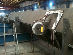
Welding is a core activity in the fabrication factory, undertaken by skilled, qualified operatives working to a welding quality management system under the control of a Responsible Welding Coordinator. It is used to prepare joints for connection in the shop and on site, and for the attachment of other fixtures and fittings. Different welding techniques are used for different activities within the fabrication factory.
Essentially, the welding process uses an electric arc to generate heat to melt the parent material in the joint. A separate filler material supplied as a consumable electrode also melts and combines with the parent material to form a molten weld pool. As welding progresses along the joint, the weld pool solidifies fusing the parent and weld metal together. Several passes or runs may be required to fill the joint or to build up the weld to the design size.
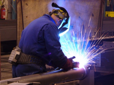

(Image courtesy of William Haley Engineering Ltd.)
[top]Principles of metal arc welding

Welding is a complex interaction of physical and chemical science. Correct prescription of metallurgical requirements and sound practical application is a prerequisite for successful fusion welds.
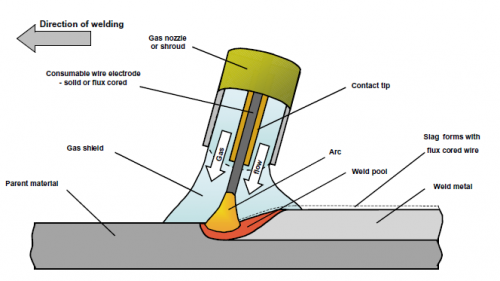
The metal arc welding process uses an electric arc to generate heat to melt the parent material in the joint. A separate filler material supplied as a consumable electrode also melts and combines with the parent material to form a molten weld pool. The weld pool is susceptible to atmospheric contamination and therefore needs protecting during the critical liquid to solid freezing phase. Protection is achieved either by using a shielding gas, by covering the pool with an inert slag or a combination of both actions.
Gas shielded processes receive gas from a remote source which is delivered to the welding arc through the gun or torch. The gas surrounds the arc and effectively excludes the atmosphere. Precise control is needed to maintain the gas supply at the appropriate flow rate as too much can produce turbulence and suck in air and can be as detrimental as too little.
Some processes use a flux, which melts in the arc to produce a slag covering which, in turn, envelops the weld pool and protects it during freezing. The slag also solidifies and self releases or is easily removed by light chipping. The action of melting the flux also generates a gas shield to assist with protection.
As welding progresses along the joint, the weld pool solidifies fusing the parent and weld metal together. Several passes or runs may be required to fill the joint or to build up the weld to the design size.
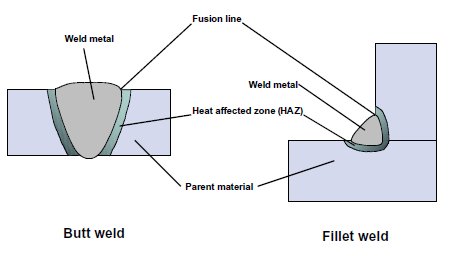
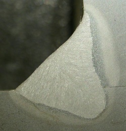
The heat from welding causes metallurgical changes in the parent material immediately adjacent to the fusion boundary or fusion line. This region of change is known as the heat affected zone (HAZ). Common terminology used in the weld area is illustrated above right.
Welding operations demand proper procedure control delivered by competent welders to ensure that design performance is achieved, to minimize the risk of defective joints caused by poor weld quality and to prevent the formation of crack susceptible microstructures in the HAZ.
[top]Types of welded connections
Most structural welded connections are carried out in the fabrication factory, and are described as either butt welds or fillet welds. Site welding is also feasible, and guidance on the considerations for site welding is available in GN 7.01.
[top]Butt welds

(Image courtesy of Mabey Bridge Ltd.)
Butt welds are normally either in-line joints in rolled sections, or in-line plate joints in webs and flanges, either to accommodate a change of thickness or to make up available material to length. The positions of these butt welds are allowed for in the design, although material availability constraints or the erection scheme may require agreement of different or additional welds. Butt-welded Tee joints may be required where there are substantial loading or fatigue considerations in transverse connections.
Butt welds are full or partial penetration welds made between bevelled or chamfered materials. Full penetration butt welds are designed to transmit the full strength of the section. It is generally possible to weld these joints from one side but, as material thickness increases, welding from both sides is desirable to balance distortion effects, with an in-process back-gouging and/or back-grinding operation to ensure the integrity of the weld root. Single-sided butt welds with backing strips, ceramic or permanent steel, are common for joining large plate areas (such as steel deck plates) and where there are closed box sections, tubes, or stiffeners, which can only be accessed for welding from one side. The design throat thickness determines the depth of penetration required for partial penetration welds. Note that fatigue considerations may limit the use of partial penetration welds, particularly on bridges. Guidance on weld preparation is available in GN 5.01.
Every effort should be made to avoid butt welding of attachments because of the costs associated with preparation, welding time, higher welder skill levels and more stringent and time-consuming testing requirements. In addition, butt welds tend to have larger volumes of deposited weld metal; this increases weld shrinkage effects and results in higher residual stress levels in the joint. Careful sequencing of welding operations is essential to balance shrinkage and to distribute residual stress, thus minimising distortion.
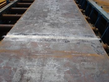
It is occasionally necessary to dress butt welds to a flush finish for fatigue reasons, or to improve drainage on weathering steel girders, or to improve the testing regime. Dressing flush for aesthetic reasons alone should be avoided because it is difficult to dress the surface to match the adjacent as-rolled surface, and the result is often more visually noticeable than the original weld. Also, grinding is an additional health and safety hazard that is best avoided as far as possible. The dressing of butt welds to a flush finish is usually not required for building steelwork as typically it is not subjected to fatigue.
- Example of a dressed butt weld with a flush finish and run-off plates
(Images courtesy of Mabey Bridge Ltd.)


[top]Fillet welds

(Image courtesy of Mabey Bridge Ltd.)
Most welded connections in building and bridgework use fillet welds, usually in a Tee configuration. They typically include end plate, stiffener, bearing and bracing connections to rolled sections or plate girders, and the web to flange connections on the plate girders themselves. These are relatively simple to prepare, weld and test in normal configurations, joint fit-up being the principal consideration.
In S275, steels full strength is also developed in fillet welds and partial penetration welds with overlying fillets provided that such welds are symmetrical, made with the correct consumables and the sum of the weld throats is equal to the thickness of the element that the welds join.
Weld sizes must be detailed on the project design drawings together with any special fatigue classification requirements. BS EN ISO 2553[1] prescribes the rules for the use of symbols to detail welded joints on drawings.
Attention is drawn to the fact that traditional UK practice has tended to use leg length to define fillet weld size, but this is not universal: throat thickness is used in European practice and BS EN 1993-1-8[2] gives requirements in relation to throat size, not leg length. The designer must be careful to ensure that it is clear which dimension is specified and all parties need to be aware of what has been specified.
[top]Processes
The important factors for the steelwork contractor to consider when selecting a welding process are the ability to fulfill the design requirements and, from a productivity point of view, the deposition rate that can be achieved and the duty cycle or efficiency of the process. (The efficiency is a ratio of actual welding or arcing time to the overall time a welder or operator is engaged in performing the welding task. The overall time includes setting up equipment, cleaning and checking of the completed weld.)
The four main welding processes in regular use in UK steelwork manufacturing are described below. The process numbers are defined in BS EN ISO 4063[3]. Variations of these processes have been developed to suit individual manufacturers’ practices and facilities, and other processes also have a place for specific applications but are beyond the scope of this article.
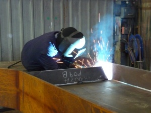
[top]Metal-active gas welding (MAG), process 135
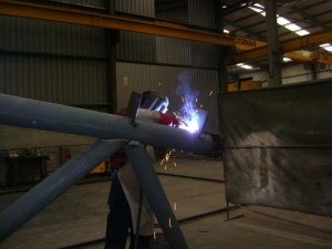

(Image courtesy of Kiernan Structural Steel Ltd.)
MAG welding with solid wire electrode is the most widely used manually controlled process for factory fabrication work; it is sometimes known as semiautomatic or CO2 welding. A continuous solid wire electrode is passed through a wire feed unit to a ‘gun’, usually held and manipulated by the operator. Power is supplied from a rectifier or inverter source along interconnecting cables to the wire feed unit and gun cable; electrical connection to the wire is made in a contact tip at the end of the gun. The arc is protected by a shielding gas, which is directed to the weld area by a shroud or nozzle surrounding the contact tip. Shielding gases are normally a mixture of argon, carbon dioxide and possibly oxygen or helium.
Good deposition rates and duty cycles can be expected with the process, which can also be mechanised with simple motorised carriages. The gas shield is susceptible to being blown away by draughts, which can cause porosity and possible detrimental metallurgical changes in the weld metal. The process is therefore better suited to factory manufacture, although it is used on site where effective shelters can be provided. It is also more efficient in the flat and horizontal positions; welds in other positions are deposited with lower voltage and amperage parameters and are more prone to fusion defects.

Metal-active gas welding (MAG), process 135
MAG welding with flux cored electrode, process 136 is a variation that utilises the same equipment as MAG welding, except that the consumable wire electrode is in the form of a small diameter tube filled with a flux. The advantage of using these wires is that higher deposition rates can be used, particularly when welding in the vertical position (between two vertical faces) or the overhead position. The presence of thin slag assists in overcoming gravity and enables welds to be deposited in position with relatively high current and voltage, thus reducing the possibility of fusion-type defects. Flux additions also influence the weld chemistry and thus enhance the mechanical properties of the joint.
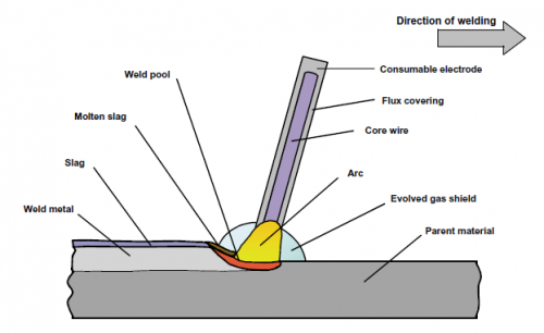
[top]Manual metal arc welding (MMA), process 111
This process remains the most versatile of all welding processes but its use in the modern workshop is limited. Alternating current transformers, DC rectifiers or inverters supply electrical power along a cable to an electrode holder or tongs. A flux coated wire electrode (or "stick") is inserted in the holder and a welding arc is established at the tip of the electrode when it is struck against the work piece. The electrode melts at the tip into a molten pool, which fuses with the parent material forming the weld. The flux also melts, forming a protective slag and generating a gas shield to prevent contamination of the weld pool as it solidifies. Flux additions and the electrode core are used to influence the chemistry and the mechanical properties of the weld.
Hydrogen controlled basic coated electrodes are generally used. It is essential to store and handle these electrodes in accordance with the consumable manufacturer’s recommendations in order to preserve their low hydrogen characteristics. This is achieved either by using drying ovens and heated quivers to store and handle the product, or by purchasing electrodes in sealed packages specifically designed to maintain low hydrogen levels.
The disadvantages of the process are the relatively low deposition rate and the high levels of waste associated with the unusable end stubs of electrodes. Nevertheless, it remains the main process for site welding and for difficult access areas where bulky equipment is unsuitable.

Manual metal arc welding (MMA), process 111
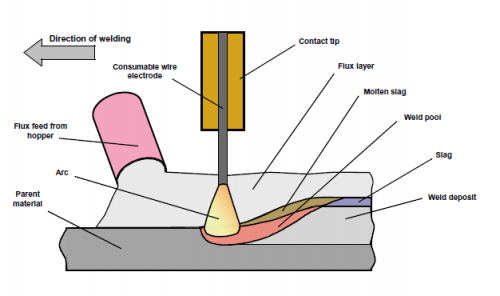
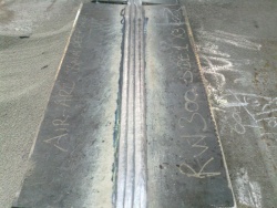
[top]Submerged arc welding (SAW), process 121

(Image courtesy of Mabey Bridge Ltd.)
This is probably the most widely used process for welding bridge web-to-flange fillet welds and in-line butt welds in thick plate to make up flange and web lengths. The process feeds a continuous wire via a contact tip, where it makes electrical contact with the power from the rectifier, into the weld area, where it arcs and forms a molten pool. The weld pool is submerged by flux fed from a hopper. The flux immediately covering the molten weld pool melts, forming a slag and protecting the weld during solidification; surplus flux is collected and re-cycled. As the weld cools, the slag freezes and peels away, leaving high quality, good profile welds.
The process is inherently safer than other processes, as the arc is completely covered during welding, hence the term submerged arc. This also means that personal protection requirements are less. High deposition rates are a feature of the process because it is normally mechanised on gantries, tractors or other purpose-built equipment. This maintains control of parameters and provides guidance for accurate placement of welds.

Submerged arc welding (SAW), process 121
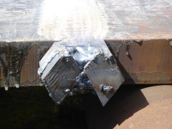
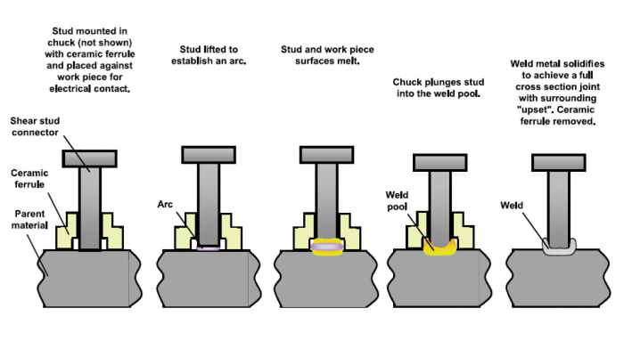
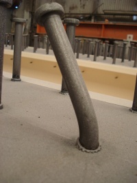
[top]Drawn arc stud welding, process 783
Composite bridges require the welding of shear stud connectors to the top flange of plate or box girders and other locations where steel to concrete composite action is required, e.g. at integral abutments. In buildings, composite beams require the welding of shear stud connectors to members, either directly to the top flange or more commonly through permanent galvanized steel decking on composite floors, where the top flange of the beam is left unpainted.
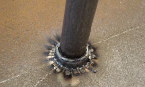
Stud weld on a bridge girder
(Image courtesy of Mabey Bridge Ltd.)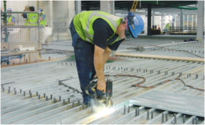
Through deck stud welding
(Image courtesy of Structural Metal Decks Ltd.)


The method of stud welding is known as the drawn-arc process and specialist equipment is required in the form of a heavy-duty rectifier and a purpose-made gun. Studs are loaded into the gun and on making electrical contact with the work, the tipped end arcs and melts. The duration of the arc is timed to establish a molten state between the end of the stud and the parent material. At the appropriate moment, the gun plunges the stud into the weld pool. A ceramic ferrule surrounds the stud to protect and support the weld pool, stabilise the arc and mould the displaced weld pool to form a weld collar. The ferrule is chipped off when the weld solidifies. Satisfactory welds typically have a regular, bright and clean collar completely surrounding the stud.

[top]Weld procedure specifications
The drawings detail the structural form, material selection and indicate welded joint connections. The steelwork contractor selects methods of welding each joint configuration that will achieve the performance required. Strength, fracture toughness, ductility and fatigue are the significant metallurgical and mechanical properties that must be considered. The type of joint, the welding position and productivity and resource demands influence the selection of a suitable welding process.
The chosen method is presented on a welding procedure specification (WPS), which details the information necessary to instruct and guide welders to assure repeatable performance for each joint configuration. An example format for a WPS is shown in Annex A of BS EN ISO 15609-1[4]. Steelwork contractors may have their own corporate template but all include the essential information to enable the proper instruction to be communicated to the welder.
It is necessary to support the WPS with evidence of satisfactory procedure tests in the form of a welding procedure qualification record (WPQR) prepared in accordance with BS EN ISO 15614-1[5]. The introduction of this standard states that welding procedure tests made to former national standards and specifications are not invalidated, provided that there is technical equivalence; additional tests may be necessary to achieve this. The major UK steelwork contractors have prequalified welding procedures capable of producing satisfactory welds in most joint configurations likely to be encountered in the steel building and bridge industry.
For circumstances where previous test data is not relevant, it is necessary to conduct a welding procedure test to establish and to confirm the suitability of the proposed WPS.
Guidance on typical welding procedure specifications for structural steelwork is available in BCSA Publication No. 58/18.
[top]Procedure tests
BS EN ISO 15614-1[5] describes the conditions for the execution of welding procedure tests and the limits of validity within the ranges of qualification stated in the standard. The welding coordinator prepares a preliminary welding procedure specification (pWPS), which is an initial proposal for carrying out the procedure test. For each joint configuration, either butt or fillet weld, consideration is given to the material grade and thickness and anticipated fit-up tolerances likely to be achieved in practice. Process selection is determined by the method of assembly, the welding position and whether mechanisation is a viable proposition to improve productivity and to provide consistent weld quality. Joint preparation dimensions are dependent upon the choice of process, any access restrictions and the material thickness.
Consumables are selected for material grade compatibility and to achieve the mechanical properties specified, primarily in terms of strength and toughness. For S355 and higher grades of steel, hydrogen-controlled products are used.
The risk of hydrogen cracking, lamellar tearing, solidification cracking or any other potential problem is assessed not only for the purpose of conducting the test but also for the intended application of the welding procedure on the project. Appropriate measures, such as the introduction of preheat or post-heat, are included in the pWPS.
Distortion control is maintained by correct sequencing of welding. Back-gouging and/or back-grinding to achieve root weld integrity are introduced as necessary.
Welding voltage, current and speed ranges are noted, to provide a guide to the optimum welding conditions.
The ranges of approval for material groups, thickness and type of joint within the specification are carefully considered to maximise the application of the pWPS. Test plates are prepared of sufficient size to extract the mechanical test specimens, including specimens for any additional tests specified or necessary to enhance the applicability of the procedure.
The plates and the pWPS are presented to the welder; the test is conducted in the presence of an examiner (usually from an independent examining body) and a record maintained of the actual welding parameters along with any modifications to the procedure needed.
Completed tests are submitted to the independent examiner for visual examination and non-destructive testing in accordance with Table 1 of the Standard. Satisfactory test plates are then submitted for destructive testing, again in accordance with Table 1. Non-destructive testing techniques are normally ultrasonic testing for volumetric examination and magnetic particle inspection for surface breaking imperfections.

(Image courtesy of Mabey Bridge Ltd.)
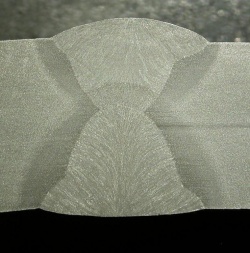
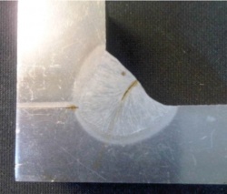
There is a series of further standards detailing with the preparation, machining and testing of all types of destructive test specimen. Normally, specialist laboratories arrange for the preparation of test specimens and undertake the actual mechanical testing and reporting. Typical specimens for an inline plate butt weld include transverse tensile tests, transverse bend tests, impact tests and a macro-examination piece on which hardness testing is performed. For impact tests, the minimum energy absorption requirements and the testing temperature are normally the same as those required for the parent material in the joint. It is wise to test all welding procedures to the limit of potential application, to avoid repeating similar tests in the future.
The completed test results are compiled into a weld procedure qualification record (WPQR) endorsed by the examiner. A typical format is shown in Annex B of BS EN ISO 15614-1[5].
There is an additional general requirement concerning welding procedure tests that where paint primers are to be applied to the work prior to fabrication, they are applied to the sample material used for the tests. In practice, careful control of paint thickness is required to avoid welding defects.
BS EN ISO 14555[6] describes the method of procedure testing for drawn arc welded stud connectors. The standard includes the test requirements necessary to prove the integrity of stud welds and it also specifies production testing requirements to monitor in-process stud welding. Qualification based on previous experience is also permitted and most steelwork contractors can provide evidence to support this.
Further guidance on weld procedure tests is available in GN 4.02.
[top]Hydrogen cracking
Cracking can lead to brittle failure of the joint, with potentially catastrophic results. Hydrogen (or cold) cracking can occur in the region of the parent metal adjacent to the fusion boundary of the weld, known as the heat-affected zone (HAZ). Weld metal failure can also be triggered under certain conditions. The mechanisms that cause failure are complex and described in detail in specialist texts.
Recommended methods for avoiding hydrogen / HAZ cracking are described in BS EN 1011-2[7], Annex C. These methods determine a level of preheating to modify cooling rates, which allows time for the hydrogen to migrate to the surface and escape (particularly if maintained as a post heat on completion of the joint) instead of becoming trapped in the hard, stressed zones. The pre-heat does not prevent the formation of crack –susceptible microstructures; it just reduces one of the factors, hydrogen, so that cracking does not occur. Preheating also lessens thermal shock.

(Image courtesy of Mabey Bridge Ltd.)
One of the parameters required to calculate preheat is heat input. A notable change in the standard is to discontinue use of the term arc energy in favour of heat input to describe the energy introduced into the weld per unit run length. The calculation of heat input is based upon the welding voltage, current and travel speed and includes a thermal efficiency factor; the formula is detailed in BS EN 1011-1[8].
High restraint and increased carbon equivalent values associated with thicker plates and higher steel grades may demand more stringent procedure controls. Experienced steelwork contractors can accommodate this extra operation and allow for it accordingly.
BS EN 1011-2[7] confirms that the most effective assurance of avoiding hydrogen cracking is to reduce the hydrogen input to the weld metal from the welding consumables. Processes with inherently low hydrogen potential are effective as part of the strategy, as well as the adoption of strict storage and handling procedures for hydrogen-controlled electrodes. Consumable suppliers’ data and recommendations provide guidance to ensure the lowest possible hydrogen levels are achieved for the type of product selected in the procedure.
Further informative Annexes in BS EN 1011-2[7] describe the influence of welding conditions on HAZ toughness and hardness and give useful advice on avoiding solidification cracking and lamellar tearing.
Further guidance on Hydrogen / HAZ cracking is available in GN 6.04.
[top]Welder qualification

(Image courtesy of Mabey Bridge Ltd.)
BS EN 1090-2[9] requires welders to be qualified in accordance with BS EN ISO 9606-1[10]. That standard prescribes tests to qualify welders based upon process, consumable, type of joint, welding position and material. Welders undertaking successful procedure tests gain automatic approval within the ranges of qualification in the standard. Welding operators are required to be approved in accordance with BS EN ISO 14732[11], when welding is fully mechanised or automatic. This standard places emphasis on testing the operator’s ability to set up and adjust equipment before and during welding.
Welder qualifications are time limited and need confirmation of validity depending on continuity of employment, engagement on work of a relevant technical nature and satisfactory performance. Prolongation of a welder’s qualification depends on recorded supporting evidence demonstrating continuing satisfactory performance within the original test range, and the evidence must include either volumetric destructive testing or destructive testing. The success of all welding operations relies on the workforce having appropriate training and regular monitoring of competence by inspection and testing.
[top]Inspection and testing
BS EN 1090-2[9] sets out the scope of inspection before, during and after welding and gives acceptance criteria related to execution class. Most testing is non-destructive; destructive testing is only carried out on run-off plates.
[top]Non-destructive testing
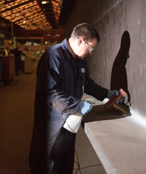

(Image courtesy of Mabey Bridge Ltd.)
Non-destructive testing is carried out in accordance with the principles in BS EN ISO 17635[12]. For constructional steelwork, the principal methods are visual inspection after welding (see GN 6.06), magnetic particle inspection (usually abbreviated to MPI or MT) for the surface inspection of welds (see GN 6.02) and ultrasonic testing (UT) for the sub-surface inspections of welds (see GN 6.03). Radiographic testing is also mentioned in BS EN 1090-2[9]. Radiography demands stringent health and safety controls; it is relatively slow and needs specialist equipment. Use of the method has declined on constructional steelwork compared with the safer and more portable equipment associated with UT. Safety exclusion zones are required, in works and on site, when radiography is in progress. However, radiography can be used to clarify the nature, sizes or extent of multiple internal flaws detected ultrasonically.
Specialist technicians with recognised training and qualifications in accordance with BS EN ISO 9712[13] are required for all non-destructive testing methods.
BS EN 1090-2[9] requires that all welds be visually inspected throughout their length. From a practical point of view, welds should be visually inspected immediately after welding, to ensure obvious surface defects are dealt with promptly.
Further non-destructive testing requirements are based upon performance techniques and require more stringent examination of the first five joints of new welding procedure specifications, to establish that the procedure is capable of producing conforming quality welds when implemented in production. Supplementary non-destructive testing based upon types of joint, rather than specific critical joints, is then specified. The intent is to sample a variety of welds based upon joint type, material grade, welding equipment and the work of welders and thereby maintain overall performance monitoring.
Where partial or percentage examination is specified, guidance on selections of test lengths is given in BS EN ISO 17635[12]; where unacceptable discontinuities are found, the examination area is increased accordingly.
BS EN 1090-2[9] also tabulates minimum hold times prior to supplementary non-destructive testing based upon weld size, heat input and material grade.
Recognising that where fatigue strength requirements are more onerous and a more stringent examination is required, BS EN 1090-2[9] does provide for the project execution specification to identify specific joints for a higher level of inspection together with the extent and method of testing.
For class EXC3, the acceptance criteria for weld imperfections is quality level B of BS EN ISO 5817[14]. Where it is necessary to achieve an enhanced level of quality to meet specific fatigue strength requirements, BS EN 1090-2[9] gives additional acceptance criteria in terms of the detail category in BS EN 1993-1-9[15] for the welded joint location.
Generally, the additional acceptance criteria are not practically achievable in routine production. Normal welding procedure testing and welder qualification tests are not assessed against the requirements of this level. Where it is necessary to achieve this level of quality, the requirements should be focussed on the relevant joint detail, so that the contractor has the opportunity to prepare welding procedure specifications, to qualify welders and to develop inspection and test techniques accordingly.
Non-destructive testing
[top]Destructive testing
There is no requirement in BS EN 1090-2[9] to carry out destructive testing for transverse joints in tension flanges. However, the scope to identify specific joints for inspection would allow the project specification to test, for example, samples from "run-off" plates attached to in-line butt welds. Additionally, production tests may be specified on: steel grades higher than S460; fillet welds where the deep penetration characteristics of the welding process are utilised; for bridge orthotropic decks where a macro examination is required to check the weld penetration; and on stiffener-to-stiffener connections with splice plates.
[top]Production testing of stud welding

(Image courtesy of Mabey Bridge Ltd.)
Stud welds for shear connectors are examined and tested in accordance with BS EN ISO 14555[6]. The standard emphasizes the need to exercise process control before, during and after welding. Pre-production testing is used to prove the welding procedure and, depending on the application, includes bend tests, tensile tests, torque tests, macro examination and radiographic examination.
Production weld tests are also required for drawn-arc stud welds. These should be performed by the manufacturer before the beginning of welding operations on a construction or group of similar constructions, and/or after a specified number of welds. Each test should consist of at least 10 stud welds and be tested / assessed in accordance with the requirements of BS EN ISO 14555[6]. The number of tests required should be specified in the contract specification.
[top]Weld quality
The effect of imperfections on the performance of welded joints depends upon the loading applied and upon material properties. The effect may also depend on the precise location and orientation of the imperfection, and upon such factors as service environment and temperature. The major effect of weld imperfections on the service performance of steel structures is to increase the risk of failure by fatigue or by brittle fracture.
Types of welding imperfection can be classified under one of several general headings:
- Cracks.
- Planar imperfections other than cracks, e.g. lack of penetration, lack of fusion.
- Slag inclusions.
- Porosity, pores.
- Undercut or profile imperfections.
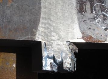
- Examples of weld defects
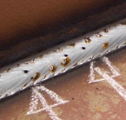
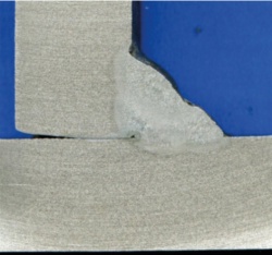


Cracks or planar imperfections penetrating the surface are potentially the most serious. Embedded slag inclusions and porosity are unlikely to initiate failure unless very excessive. Undercut is not normally a serious problem unless significant tensile stresses exist transverse to the joint.
By selecting an execution class in BS EN 1090-2[9], acceptance criteria are established, beyond which the imperfection is considered a defect.
Where defects are detected as a result of inspection and testing during production, post-weld dressing (see GN 5.02) or other remedial measures are likely to be necessary, although in many cases the particular defect may be assessed on the concept of ‘fitness for purpose’. Such acceptance is dependent upon the actual stress levels and the significance of fatigue at the location. This is a matter for speedy consultation between the steelwork contractor and the designer for, if acceptable, costly repairs (and the potential for introducing further defects or distortion) can be avoided.
Guidance on the control of weld quality and weld inspection is available in BCSA No. 54/12 and GN 6.01
[top]References
- ↑ BS EN ISO 2553:2019, Welding and allied processes. Symbolic representation on drawings. Welded joints. BSI.
- ↑ BS EN 1993-1-8:2005, Eurocode 3. Design of steel structures. Design of joints, BSI
- ↑ BS EN ISO 4063:2010, Welding and allied processes. Nomenclature of processes and reference numbers, BSI
- ↑ BS EN ISO 15609-1:2019, Specification and qualification of welding procedures for metallic materials. Welding procedure specification. Arc welding, BSI
- ↑ Jump up to: 5.0 5.1 5.2 BS EN ISO 15614-1:2017+A1:2019, Specification and qualification of welding procedures for metallic materials. Welding procedure test. Arc and gas welding of steels and arc welding of nickel and nickel alloys, BSI
- ↑ Jump up to: 6.0 6.1 6.2 BS EN ISO 14555:2017, Welding. Arc stud welding of metallic materials, BSI
- ↑ Jump up to: 7.0 7.1 7.2 BS EN 1011-2:2001, Welding. Recommendations for welding of metallic materials. Arc welding of ferritic steels, BSI
- ↑ BS EN 1011-1:2009, Welding. Recommendations for welding of metallic materials. General guidance for arc welding, BSI
- ↑ Jump up to: 9.0 9.1 9.2 9.3 9.4 9.5 9.6 9.7 9.8 BS EN 1090-2:2018, Execution of steel structures and aluminium structures. Technical requirements for steel structures, BSI
- ↑ BS EN ISO 9606-1:2017 Qualification testing of welders. Fusion welding. Steels, BSI
- ↑ BS EN ISO 14732:2013. Welding personnel. Qualification testing of welding operators and weld setters for mechanized and automatic welding of metallic materials BSI
- ↑ Jump up to: 12.0 12.1 BS EN ISO 17635:2016, Non-destructive testing of welds. General rules for metallic materials, BSI
- ↑ BS EN ISO 9712:2022. Non-destructive testing. Qualification and certification of NDT personnel, BSI
- ↑ BS EN ISO 5817:2014, Welding. Fusion-welded joints in steel, nickel, titanium and their alloys (beam welding excluded). Quality levels for imperfections, BSI
- ↑ BS EN 1993-1-9:2005, Eurocode 3. Design of steel structures. Fatigue, BSI
[top]Resources
- Steel Buildings, 2003, (Publication No. 35/03), BCSA
- Steel Bridges: A practical approach to design for efficient fabrication and construction, 2010, (Publication no. 51/10), BCSA
- National Structural Steelwork Specification (7th Edition), 2020, (Publication No. 62/20), BCSA
- Commentary (3rd edition) on the National Structural Steelwork Specification for Building Construction (7th edition), 2022, (Publication No. 66/22), BCSA
- Typical Welding Procedure Specifications for Structural Steelwork - Second Edition, 2018, (Publication No. 58/18), BCSA
- High Strength Steels for Structural Applications: A Guide for Fabrication and Welding, 2020, (Publication No. 63/20), BCSA
- Guide to Weld Inspection for Structural Steelwork, 2012, (Publication No. 54/12), BCSA
- Hendy, C.R.; Iles, D.C. (2015) Steel Bridge Group: Guidance Notes on best practice in steel bridge construction (6th Issue). (P185). SCI
- Guidance Note 4.02 Weld procedure tests
- Guidance Note 5.01 Weld preparation
- Guidance Note 5.02 Post-weld dressing
- Guidance Note 6.01 Control of weld quality and inspection
- Guidance Note 6.02 Surface inspection of welds
- Guidance Note 6.03 Sub-surface inspection of welds
- Guidance Note 6.04 Hydrogen / HAZ cracking and solidification cracking in welds
- Guidance Note 6.06 Visual inspection after welding
- Guidance Note 7.01 Site welding
[top]Further reading
- Steel Designer’s Manual (7th Edition), 2011, Chapter 26 - Welds and design for welding, The Steel Construction Institute.