


Material selection and product specification
Steel material is supplied in two product forms – ‘flat products’ (steel plate and strip) and ‘long products’ (rolled sections, either open beams, angles, etc or hollow sections). For structural use in bridges these products are inevitably cut (to size and shape) and welded, one component to another. In the structure, the material is subject to tensile and compressive forces. Structural steel generally responds in a linear elastic manner, up to the ‘yield point’ and thereafter has a significant capacity for plastic straining before failure. All these aspects of steel material are utilised by the designer of a steel bridge.
The selection of an appropriate grade of steel for a bridge requires an awareness of the steel manufacturing process, an appreciation of the relevant product standards and design specifications, and an understanding of several issues including material properties, availability and cost. This article provides designers with background information and specific guidance on how to select an appropriate steel grade and quality, and on how the structural steel products for a bridge are specified in accordance with the Structural Eurocodes.

[top]Material properties
[top]General
Steel derives its material properties from a combination of chemical composition, mechanical working and heat treatment.
The chemical composition is fundamental to the mechanical properties of steel. Adding alloys such as Carbon, Manganese, Niobium and Vanadium can increase the strength. However, such alloy additions increase the cost of the steel, and can adversely affect other properties (i.e. ductility, toughness and weldability). Keeping the sulphur level low can enhance the ductility, and the toughness can be improved by the addition of Nickel. Hence, the chemical composition for each steel specification has been carefully chosen to achieve the required properties.

Plates and sections are produced by rolling steel slabs, blooms or billets (at a high temperature) until the required plate or section size is achieved. This rolling is the mechanical working that refines the grain structure and determines the mechanical properties. The more steel is rolled, the stronger it becomes. This effect is readily apparent in material standards, which specify reducing levels of minimum yield strength with increasing material thickness. However, although rolling increases the strength, it also reduces the ductility of the steel.
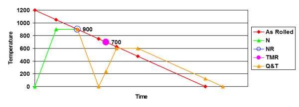
The effect of heat treatment is best explained by reference to the different production processes or rolling regimes that can be used in steel manufacturing , the main ones being:
- As-rolled steel
- Normalized steel
- Normalized-rolled steel
- Thermomechanically rolled (TMR) steel
- Quenched and tempered (QandT) steel
Steel cools as it is rolled, and the typical rolling finish temperature is 750°C, after which the steel cools naturally. Steel produced through this route is termed ‘As-rolled’. Structural sections generally achieve the required mechanical properties through this efficient production route, but plates usually require further heat treatment.
Normalizing is the process where an as-rolled plate is heated back up to approximately 900°C, and held at that temperature for a specific time, before being allowed to cool naturally. This process refines the grain size and improves the mechanical properties, specifically the toughness. It renders the properties more uniform, and removes residual rolling strains.
Normalized-rolled is a process where the rolling finish temperature is above 900°C, and the steel is allowed to cool naturally. This has a similar effect on the properties as Normalizing, but it eliminates a process. Normalized and Normalized rolled steels are denoted ‘N’
Thermomechanical rolled steel utilises a leaner chemistry, which requires a lower rolling finish temperature of 700°C to put the strength in, before the steel cools naturally. Note that greater force is required to roll the steel at these lower temperatures, and that the properties are retained unless reheated above 650°C. Thermomechanical rolled steel is denoted ‘M’
The process for Quenched and Tempered steel starts with an as-rolled plate, heats it back to 900°C and holds it at that temperature, as for normalizing, but then the steel is rapidly cooled or ‘quenched’ to produce steel with high strength and hardness, but low toughness. The toughness is restored by reheating it to 600°C, maintaining the temperature for a specific time, and then allowing it to cool naturally (‘tempering’). Quenched and tempered steels are denoted ‘Q’.

[top]Mechanical properties
The mechanical properties of particular importance to the bridge designer include:
[top]Weldability

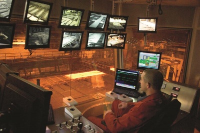
(Image courtesy of Mabey Bridge Ltd.)
All structural steels are essentially weldable. However, welding involves locally heating the steel material, which subsequently cools. The cooling can be quite fast, because the material offers a large ‘heat sink’ and the weld (and the heat introduced) is relatively small. This can lead to hardening of the ‘heat affected zone’ and to reduced toughness. The significance of this effect increases as the plate thickness increases.
The susceptibility to embrittlement also depends on the alloying elements, principally, but not exclusively, on the carbon content. This susceptibility can be expressed as the ‘Carbon Equivalent Value’ (CEV). The CEN product standards (e.g. EN 10025-1[1]) give an expression for determining this value, and specify mandatory limits on the maximum CEV. Welding standards (e.g. EN 1011-2[2]) will indicate what preheat, if any, is needed for a given CEV, material thickness and weld size.
[top]Corrosion protection
All structural steels, with the exception of weathering steel, have a similar resistance to corrosion. In exposed conditions they need to be protected by a coating system. There are no special requirements of the steel material for ordinary coating systems, including both aluminium and zinc metal spray. However, if the steel is to be galvanized, then there is a need to control the alloy content (notably the Silicon content), this can be achieved simply by specifying that the steel be “suitable for hot dip zinc-coating” (option 5 in EN 10025-1[1]).
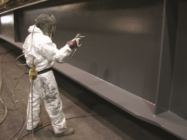
Coating application
(Image courtesy of Mabey Bridge Ltd.)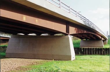
A weathering steel bridge
(Westgate Bridge, Gloucester.)


Weathering steel is a high strength low alloy steel that in suitable environments forms an adherent protective rust ‘patina’, to inhibit further corrosion. The corrosion rate is so low that bridges fabricated from unpainted weathering steel can achieve a 120 year design life with only nominal maintenance.
[top]Design requirements
EN 1993-2[3]), Section 3, Materials describes the requirements for structural steel for bridgeworks, and contains the following clauses:
- 3.1 General
- 3.2 Structural steel
- 3.2.1 Material properties
- 3.2.2 Ductility requirements
- 3.2.3 Fracture toughness
- 3.2.4 Through thickness properties
- 3.2.5 Tolerances
- 3.2.6 Design values of material coefficients
EN 1993-2[3] makes the assumption that execution is carried out in accordance with EN1090-2[4], which includes clauses for steel product specifications.
[top]General - Product standards
All new structural steel for use in bridges should be manufactured to a CEN European Standard (EN). These product standards are issued in the UK by BSI, with a short National Foreword (that occasionally makes minor modifications to the Standard), and consequently bear the BS EN designation before the reference number. The following CEN product standards are relevant to bridge steelwork: EN 10025 (For plates and open sections)
- Part 2[5] - Non alloy structural steels
- Part 3[6] - Fine grain structural steels (Normalized / Normalized rolled)
- Part 4[7] - Fine grain structural steels (Thermomechanical rolled)
- Part 5[8] - Weathering steels
- Part 6[9] - Quenched and tempered steels
EN 10210-1[10] (For hot rolled structural hollow sections)
EN 10219-1[11] (For cold formed structural hollow sections)
In the CEN designation system for steel material all structural steels have the prefix “S”. This letter is followed a three digit reference that corresponds to the yield strength (in N/mm2) and by various other letters and numerals that indicate other properties or process routes. A summary of the grades available in these standards, up to a yield strength of 460 N/mm2, is given in Guidance Note 3.01.
[top]Structural steel
[top]Yield strength
The yield strength is probably the most significant property that the designer will need to use or specify. The achievement of a suitable strength whilst maintaining other properties has been the driving force behind the development of modern steel making and rolling processes.
In the CEN product standards, the primary designation relates to the yield strength, e.g. S355 steel is a structural steel with a minimum yield strength (ReH) of 355 N/mm2. The number quoted in the designation is the value of yield strength for material up to 16 mm thick. Designers should note that yield strength reduces with increasing plate or section thickness. An example for common steels to EN 10025-2[5] is given in the table below.
| Steel grade | Nominal thickness (mm) | |||||
|---|---|---|---|---|---|---|
| ≤ 16 | > 16 ≤ 40 |
> 40 ≤ 63 |
> 63 ≤ 80 |
> 80 ≤ 100 |
> 100 ≤ 150 | |
| S275 | 275 | 265 | 255 | 245 | 235 | 225 |
| S355 | 355 | 345 | 335 | 325 | 315 | 295 |
| S460 | 460 | 440 | 420 | 400 | 390 | 390 |
In the UK, the nominal values of the yield strength (fy) for structural steel, and hence the characteristic values used in design calculations, are obtained by adopting the minimum yield strength (ReH) values direct from these product standards.
S275 steel is often used on railway bridges, where stiffness rather than strength governs the design, or where fatigue is the critical design case. S355 steel is predominantly used in highway bridge applications, as it is readily available, and generally gives the optimum balance between stiffness and strength.
S460 steels can offer advantages where self-weight is critical or the designer needs to minimise plate thicknesses. However, the use of such steels confers no benefits in applications where fatigue, stiffness or the instability of very slender members is the overriding design consideration. These steels are also less readily available in the UK.
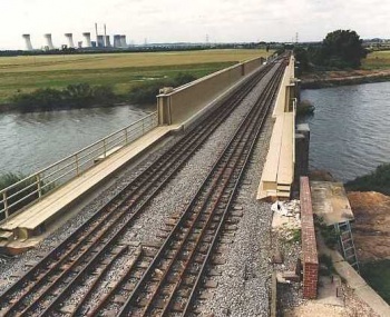
A typical railway bridge using S275 steel
(Trent Rail Bridge, Gainsborough)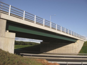
A typical highway bridge using S355 steel, A1 Appleyhead


Yield strengths above 460 N/mm2 are available to EN 10025-6[9], and additional design requirements for these higher strength steels are contained in EN 1993-1-12[12]. The associated UK National Annex (NA)[13] specifies a minimum fu / fy ratio of 1.10 rather than the recommended value of 1.05 for these steels. However, this more onerous requirement is of limited relevance, because fu and fy are the specified ultimate tensile and yield strengths respectively, and steels to EN 10025-6[9] meet this more onerous limit.
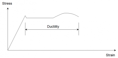
[top]Ductility requirements
Ductility is of paramount importance to all steels in structural applications. It is a measure of the degree to which the material can strain or elongate between the onset of yield and eventual fracture under tensile loading. Whether it is realised or not, the designer relies on ductility for a number of aspects of design: redistribution of stress at the ultimate limit state; bolt group design; reduced risk of fatigue crack propagation; and in the fabrication processes of welding, bending, and straightening, etc.
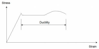
Ductility tends to reduce with increasing yield strength. Fortunately, this effect is not significant enough to affect the design of the majority of bridges. Ductility of a steel plate or rolled section is measured in relation to behaviour either in plane (parallel to or transverse to the direction of rolling) or perpendicular to the plane of the element.
In-plane ductility
The requirements for in-plane ductility of steel used in bridges in the UK are as follows:
- Ratio of the ultimate tensile strength to the yield strength (fu / fy) ≥ 1.10
- Elongation at failure based on a standard proportional gauge length ≥ 15%
- The ratio of the ultimate strain to the yield strain (εu / εy) ≥ 15
All steel conforming to the CEN product standards mentioned in section 3.1 meets these requirements, so no additional specification is needed for in-plane ductility.
Through-thickness ductility
The properties of steel perpendicular to the plane of the element (often termed through thickness properties) are different from those in plane. This is particularly true for ductility, which is generally lower in the direction perpendicular to the plane of rolling.
[top]Fracture toughness
The nature of steel material is that it always contains some imperfections, albeit of very small size. When subject to tensile stress these imperfections (similar to very small cracks) tend to open. If the steel is insufficiently tough, the ‘crack’ propagates rapidly, without plastic deformation, and failure may result. This is called ‘brittle fracture’, and is of particular concern because of the sudden nature of failure. The toughness of the steel, and its ability to resist this behaviour, decreases as the temperature decreases. In addition, the toughness required, at any given temperature, increases with the thickness of the material.

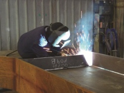
(Image courtesy of Mabey Bridge Ltd.)
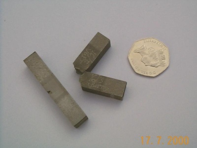
A convenient measure of toughness is the Charpy V-notch impact test (hence the term “notch toughness” has been widely used in the past). This test measures the impact energy (in Joules) required to break a small, notched specimen by a single impact blow from a pendulum. The tests are carried out with the specimens at specified (low) temperatures, and the CEN product standards specify the required minimum impact energy values for different grades. Refer to Table 1 in Guidance Note 3.01.
In the CEN product standards there is no universal designation system for the fracture toughness. In standards EN 10025: Part 2[5] and EN 10210-1[10] and EN 10219-1[11] there is a two character alphanumeric code; there are three different codes that are relevant for bridges in the UK:
- J0: = 27J impact energy at 0°C
- J2: = 27J impact energy at -20°C
- K2: = 40J impact energy at -20°C
Steels to EN 10025: Part 5[8] have the same codes, but introduce two additional tougher grades:
- J4: = 27J impact energy at -40°C
- J5: = 27J impact energy at -50°C
Steels to EN 10025: Part 3[6] and Part 4[7] and fine grain steels to EN 10210-1[10] and EN 10219-1[11] may be one of two categories of impact strength, the lower-temperature one being designated by the code ‘L’.
- _: = 40J impact energy at -20°C
- L: = 27J impact energy at -50°C
Steels to EN 10025: Part 6[9] (Q and T steels) may be one of three grades of toughness; the lower-temperature two grades being designated by the codes L and L1.
- _: = 30J impact energy at -20°C
- L: = 30J impact energy at -40°C
- L1: = 30J impact energy at -60°C
The requirements for fracture toughness are described in EN 1993-1-10[14] and its associated UK NA[15]. The procedure requires the calculation of a reference temperature (TEd), which is then used to determine a maximum permitted thickness for the steel part from a set of tabulated values. The end result depends on the following:
- Steel material properties (yield strength and toughness)
- Member characteristics (shape, detail and stress concentrations etc.)
- Design situation (steel temperature, stress and degree of cold forming)
The ‘accidental combination’ of actions to be considered for this design case is described in EN 1993-1-10[14] and the design effects are expressed in equation 2.1 as:
Ed = E { A[TEd] + ΣGK + ψ1QK1 + Σ ψ2,iQKi }
The effect of the reference temperature is not a stress but the susceptibility to brittle fracture. The effect of the other actions is the stress in the component being considered. In this combination, the reference temperature is considered the ‘leading action’ and the main accompanying action (QK1) is taken at its frequent value. The other accompanying actions are taken at their quasi-permanent values (which in most cases are zero). No partial factors are applied, since this is an accidental design situation (see EN 1990[16], clause 6.4.3.3.)
Calculation of the reference temperature (TEd)
TEd = Tmd + ΔTr + ΔTσ + ΔTR + ΔTέ + ΔTέcf
- (Tmd + ΔTr) considered together represent the minimum effective temperature of the steel part, and should be determined according to EN 1991-1-5[17] and its associated UK NA[18].
- ΔTσ is an adjustment for the relative level of stress, and should be taken as 0°C, as the UK NA[15] accounts for this in the determination of ΔTR.
- ΔTR is a safety allowance, which is determined in accordance with the UK NA[15] as follows: ΔTR = ΔTRD + ΔTRg + ΔTRT + ΔTRσ + ΔTRs
- ΔTRD is an adjustment for the detail type (UK NA[15] 2.1.1.2).
- ΔTRg is an adjustment for gross stress concentrations. (UK NA[15] 2.1.1.3).
- ΔTRT is an adjustment for the Charpy test temperature. (UK NA[15] 2.1.1.4).
- ΔTRσ is an adjustment for the applied stress level. (UK NA[15] 2.1.1.5).
- ΔTRs is an adjustment for the strength grade. (UK NA[15] 2.1.1.6).
- ΔTRD is an adjustment for the detail type (UK NA[15] 2.1.1.2).
- ΔTέ is an adjustment for high strain rates that would occur if, say, a vehicle struck the bridge. However, the coexistence of two accidental actions (i.e. min. temperature and vehicle impact load) is contrary to the combination of actions specified by EN 1993-1-10[14] for the determination of fracture toughness. Hence, ΔTέ should generally be taken as 0°C. However, there is an argument for applying ΔTέ for parts particularly prone to risk of accidental impact forces (e.g. edge girders on decks with substandard headroom, i.e. less than 5.3m)
- ΔTέcf is an adjustment to allow for the degree of cold forming. This is significant, as typical inside bend radii for cold formed sections are 2x thickness, which results in a strain of 20% and a temperature shift ΔTέcf of -60°C. This could rule out the use of a cold-formed section.
Determination of the maximum permitted thickness
Once the reference temperature has been determined, the next step is to refer to Table 2.1 of EN 1993-1-10[14], and the extension to lower reference temperatures given in Table 1 of PD 6695-1-10[19], to determine the maximum permitted thickness for the particular steel grade.
Example calculations
Consider a typical multi-girder steel composite bridge deck in Scunthorpe, and assume it has 100mm surfacing.
Minimum shade air temperature (UK NA[18] - Figure NA.1) = -14°C
Adjustment for height above sea level (EN 1991-1-5[17], A.1, note 2) = 0°C
Conversion for 120-year return period (EN 1991-1-5[17], Figure A.1) = x1.14
Hence, Tmin = 1.14 x (-14°C - 0°C) = -16°C
Minimum effective bridge temperature of the steel part,
For a Type 2 deck, and Tmin = -16°C, from Figure 6.1 (EN 1991-1-5[17]), Te, min = -12°C
Hence, (Tmd + ΔTr) = -12 °C
ΔTR = ΔTRD + ΔTRg + ΔTRT + ΔTRσ + ΔTRs
The welded details on the bottom flange of a typical fabricated plate include web / flange, the attachment of transverse web stiffeners, and (pre-assembly) transverse butt welds. However, none of these are ‘severe’ details described in Table NA.1.
Hence, ΔTRD = 0°C
A well-detailed typical plate girder is unlikely to have any stress concentrations.
Hence, ΔTRg = 0°C
The adjustment for the Charpy test temperature applies only to buildings, as the use of steel at temperatures more than 20 oC below the test temperature is not permitted.
Hence, ΔTRT = 0°C
Conservatively assume that the bottom flange stress is 0.75fy(t)
Hence, ΔTRσ = 0°C
Assume that the steel grade is S355
Hence, ΔTRs = 0°C
Consequently, ΔTR = 0°C
TEd = Tmd + ΔTr + ΔTσ + ΔTR + ΔTέ + ΔTέcf
Assuming that the deck complies with the minimum headroom criteria (5.3m), and that there is no cold bending of the bottom flange (i.e. ΔTέcf = 0°C), and remembering that ΔTσ = 0°C
Then, TEd = -12 °C
The design calculations resulted in a requirement for a 55m thick bottom flange in grade S355 steel. So, for TEd = -12 °C, and with reference to Table 2.1 of EN 1993-1-10[14] the maximum permitted thicknesses are: J0 = 39mm, J2 = 58mm, and K2 = 72mm.
Hence, the required steel subgrade is J2
A simplified procedure is given in Table 4 of PD 6695-1-10[19]. This assumes a minimum air temperature of -20°C, which is expected to cover most bridge locations in the UK, and ignores the radiation loss (ΔTr) which is conservative for steel composite decks.
However, use of this simplified procedure on the example above would have resulted in a requirement for the steel subgrade to be K2 rather than J2.
[top]Through thickness properties
Background
As mentioned previously, the properties of steel perpendicular to the plane of the element (often termed through-thickness) are different from those in plane.
The nature of the production process is such that any inclusions or discontinuities in the steel are essentially ‘rolled-out’ to be planar in extent and parallel to the surface of the plate. The result is that the mechanical properties in the through thickness direction are more susceptible to the influence of such inclusions or discontinuities.
There are two types of imperfection that affect through thickness behaviour:
- macro imperfections - thin layers of inclusions or discontinuities, extending over an area
- micro imperfections - numerous very small inclusions or discontinuities.
Macro imperfections are termed ‘laminations’ or ‘laminar defects’. The presence and extent of such defects can be checked by ultrasonic testing, and acceptance levels are given in EN 10160[20].
Micro imperfections are significant when the material is subject to through-thickness stress, because they can lead to ‘lamellar tearing’ as a tear propagates from one inclusion to the next. The inclusions are small, so they cannot readily be revealed by ultrasonic testing. However, their effect may be assessed by carrying out through thickness tensile tests in accordance with EN 10164[21].
These tensile tests are used to establish the through thickness ductility of the steel, and categorise it into one of three levels (Z15, Z25 or Z35). The letter ‘Z’ merely indicates the direction of the tensile test, i.e. perpendicular to the ‘x-y’ plane of the plate. The numerical value indicates the minimum percentage reduction of area at failure of the small test specimens of plate material. High ductility is indicated by a high percentage (e.g. Z35 corresponds to a 35% average reduction in area at failure).

The need for Z-grade steel
Improvements in steel manufacturing over the years mean that steel from modern mills is much cleaner, and less likely to contain significant levels of micro imperfections than in the past. The through thickness ductility of such steels is sufficient for most applications, and is typically equivalent to Z15 or Z25 material. Hence, there should be very little need to specify Z-grade steel in typical well-designed bridge steelwork.
Z-grade steel might be required where high loads are transmitted through T-section or cruciform details, and where large welds are specified on elements that are restrained against shrinkage. Guidance Note 3.02 contains detailed advice on situations where Z-grade steel is needed to minimise the risk of ‘lamellar tearing’.
However, the requirements for Z-grade steel are usually very local in nature, and as such only small quantities will be needed. Additionally, Z-grade steel is more expensive and less readily available than conventional structural steel. Consequently, it is better to design details that do not require the use of steel with improved through thickness properties, if possible. Nevertheless, if Z-grade steel is needed, it should be specified as a ‘option’ (4) in EN 10025-1[1] in terms of one of the three ‘levels’ (Z15, Z25 or Z35) of through thickness ductility according to EN 10164[21].
Which Z-grade to specify?
EN 1993-1-10[14] contains a numerical method for determining the required Z-grade according to the weld size, detail type and level of restraint. However, the UK NA[15] indicates that this need not be used. The view of the UK experts is that this numerical method is unduly conservative, requires extensive calculations, and would lead to the unnecessary specification of Z-grade material. Instead, the UK NA refers designers to a BSI document, PD 6695-1-10[19], which gives:
- Options for the fabricator. The risk of ‘lamellar tearing’ can be mitigated by following certain fabrication control measures such as procuring material from a modern mill known to produce clean steel.
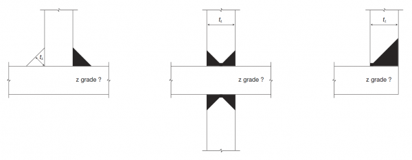
- Options for the designer. The PD says that Z-grade material need not be specified for low and medium risk situations. It recommends that designers should specify Z35 quality to EN 10164[21], only for high risk situations and defines such high risk situations as:
- T (tee) joints, tz > 35mm.
- X (cruciform) joints, tz> 25mm.
- L (corner) joints, tz > 20mm.
Where tz is the thickness of the incoming plate for butt welds and deep penetration fillet welds, and for fillet welded joints, tz is the throat size of the largest fillet weld.

[top]Tolerances
This clause in EN 1993-2[3] merely states that rolled steel products should conform to the tolerances in the relevant product standard and that for fabricated components the tolerances in EN 1090-2[4] should apply.
[top]Design values of material coefficients
The material coefficients to be used in the design calculations for steel bridges are:
- Modulus of elasticity, E = 210,000 N/mm2
- Shear modulus, G = 80,000 N/mm2
- Poisson’s ratio in elastic stage, v = 0.3
- Coefficient of linear thermal expansion = 12 x 10-6/°C
However, for calculating the structural effects of temperature difference (vertical and horizontal temperature gradients in the cross section) in steel-concrete composite bridge decks to EN 1994-2[22], the coefficient of linear thermal expansion should be taken as 10 x 10-6/°C.
[top]Availability and cost of steel
The general availability of structural steel sections for bridgeworks is outlined in the following British Steel and Tata Steel product brochures:
- British sections product range datasheets, British Steel
- Celsius® 355 NH technical guide, Structural hollow sections, Tata Steel
and the following publications from ArcelorMittal:
[top]Availability of plates
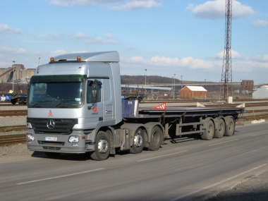
Plates are readily available in a wide range of sizes and material grades in the UK, and may be obtained either direct from the mill, or through a steel stockholder.
The advantage of obtaining plates direct from the mill is that they are rolled to order, specifically to a chosen size, which minimises waste and maximises design efficiency, as any intermediate thickness is available. Web and flange plates are generally procured through this route, so maximum efficiency is achieved by specifying the actual thickness required according to the design calculations. Rounding up to the nearest 5mm is not advisable as it merely increases the cost of the steelwork. Normal plate sizes range from 5mm to 200mm thick, with widths up to 3.5m and lengths up to 18.0m.
Steel from a stockholder is more suited to small quantities, and will reduce lead times. However, it will be more expensive, and the size and quality required may not be readily available. It is important to trace the source of the steel and obtain the appropriate mill certificates. Typical stock sizes are illustrated below, and thicknesses are generally in 5mm increments. Plates for stiffeners are typically procured from stockholders, so the thickness of stiffeners should be rounded up to the nearest 5mm.
| 4000 x 2000 |
5000 x 2500 |
6000 x 2000 |
6000 x 3000 |
8000 x 2000 |
9000 x 3000 |
10000 x 2500 |
12000 x 2500 |
Plates direct from the mill
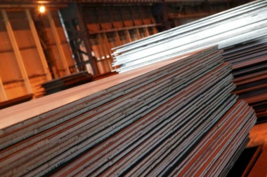
Plates from a stockholders yard


[top]The cost of steelwork
The cost of fabricated and erected steelwork in terms of £/tonne is highly variable, and dependent on a number of factors including the state of the market, grade of steel, degree of fabrication , site location, corrosion protection system and access for erection. Hence, for cost comparisons at critical stages in a project’s development it is suggested that designers contact a major steelwork contractor, most of whom would be pleased to advise on budget estimates.
[top]Product specifications
[top]General
The execution standard for steel bridges designed to the Eurocodes is EN 1090-2[4]. It includes requirements related to the supply of products and refers to the appropriate product standards for their specification. EN 1090-2[4] has numerous provisions where additional requirements or decisions on optional requirements may be specified; some of these relate to the steel products. Different projects will almost certainly have different execution specifications, but the use of standard specifications, such as the Specification for Highway Works[23], is recommended to ensure consistency across the industry.
The following sections describe the key requirements relating to steel products that are specified in either EN 1090-2[4] and its reference standards or in the Specification for Highway Works[23]. Note that Network Rail's Specification for structural steelwork[24] has similar requirements.
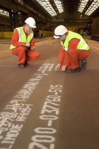
[top]Identification, inspection documents and traceability
A record should be maintained of the source of, and test certificates for, main structural steel elements including each flange and web in order to provide traceability. This requirement is implemented by the Specification for Highway Works[23].
[top]Constituent steel products
[top]General
The chosen grade(s) of steel are specified to the standards listed in EN 1090-2[4] and the grade (and sub-grade) should be stated on the drawings.
Guidance on the specification of tension bar components is available in Guidance Note 4.05
[top]Thickness tolerances
For plates, Class A to EN 10029[25] is usually sufficient, even where Execution Class 4 is specified. Class A is the default in EN 10025-2[5] and its selection is confirmed in the Specification for Highway Works[23]. The thickness tolerances in Class A increase with the nominal thickness as follows:
| Nominal thickness | Lower tolerance | Upper tolerance |
|---|---|---|
| ≥ 8 < 15 | -0.5 | +0.9 |
| ≥ 15 < 25 | -0.6 | +1.0 |
| ≥ 25 < 40 | -0.7 | +1.3 |
| ≥ 40 < 80 | -0.9 | +1.7 |
[top]Surface conditions

Class A3 (for plates) and Class C3 (for sections) to EN 10163[26] are generally appropriate.
Although steel is visually inspected before it leaves the mill, it is not usually blast cleaned and still has mill scale adhering to it. Consequently, the surface that is revealed after grit blasting may show surface discontinuities that were not visible before. EN 10163[26] defines the requirements relating to surface condition and refers to ‘imperfections’ (discontinuities that may be left without repair) and to ‘defects’ (discontinuities that shall be repaired).
For plates, Class A means that shallow depth imperfections are acceptable, but defects, including cracks, shell and seams, must be repaired (i.e. ground out). EN 10163[26] defines ‘shallow depth’, and sets limits on the depth and areas of ground repairs. Sub-class 3 means that repair by welding is not allowed. This is appropriate for bridges because there would be no control over the location of any repairs, which could end up in fatigue-prone zones.
For further information on surface defects on steel materials, refer to Guidance Note 3.05.
[top]Internal discontinuities
The locations where internal discontinuity quality Class S1 (to EN 10160[20]) is required should be shown on the drawings. Guidance on where this is needed is given in EN 1090-2[4], the Specification for Highway Works[23], Guidance Note 3.06 and examples include:
- A band width of 4x the plate thickness either side of a welded attachment in a cruciform joint transmitting tensile stress through the plate thickness.
- A band width of 25x the web or flange plate thickness either side of a bearing diaphragm if attached by welding.
- A band width of 25x the web plate thickness either side of a single-sided bearing stiffener if attached by welding.
Class S1 is an acceptance level for macro imperfections (termed ‘laminations’ or ‘laminar defects’), the presence and extent of which are checked by ultrasonic testing. Scanning comprises a continuous examination along the lines of a 200mm square grid parallel to the edge of the plate. If a discontinuity is encountered, its extent is then established. The acceptable limits for discontinuities (for Class S1) are as follows:
- Individual discontinuity: - Area ≤ 1000mm2
- Clusters of discontinuities: - 15 in the most populated 1m x 1m square (individual discontinuities < 100mm2 are ignored)
It is also recommended that edge discontinuity class E1 should be specified for the edges of plates where corner welds will be made on to the surface of such plates.
For further information on surface defects on steel materials, refer to Guidance Note 3.06.
[top]Case studies


[top]References
- ↑ 1.0 1.1 1.2 BS EN 10025-1: 2004, Hot rolled products of structural steels, Part 1: General technical delivery conditions, BSI
- ↑ BS EN 1011-2: 2001, Welding recommendations for welding of metallic materials. Part 2: Arc welding of ferritic steels. BSI
- ↑ 3.0 3.1 3.2 BS EN 1993-2: 2006, Eurocode 3: Design of steel structures. Part 2: Steel Bridges, BSI
- ↑ 4.0 4.1 4.2 4.3 4.4 4.5 4.6 BS EN 1090-2: 2018, Execution of steel structures and aluminium structures. Technical requirements for steel structures. BSI
- ↑ 5.0 5.1 5.2 5.3 BS EN 10025-2: 2019, Hot rolled products of structural steels, Part 2: Technical delivery conditions for non-alloy structural steels, BSI
- ↑ 6.0 6.1 BS EN 10025-3: 2019, Hot rolled products of structural steels, Part 3: Technical delivery conditions for normalized / normalized rolled weldable fine grain structural steels, BSI
- ↑ 7.0 7.1 BS EN 10025-4: 2019 +A1:2022, Hot rolled products of structural steels, Part 4: Technical delivery conditions for thermomechanical rolled weldable fine grain structural steels, BSI
- ↑ 8.0 8.1 BS EN 10025-5: 2019, Hot rolled products of structural steels, Part 5: Technical delivery conditions for structural steels with improved atmospheric corrosion resistance, BSI
- ↑ 9.0 9.1 9.2 9.3 BS EN 10025-6: 2019 +A1:2022, Hot rolled products of structural steels, Part 6: Technical delivery conditions for flat products of high yield strength structural steels in the quenched and tempered condition, BSI
- ↑ 10.0 10.1 10.2 BS EN 10210-1: 2006, Hot finished structural hollow sections of non-alloy and fine grain structural steels. Part 1: Technical delivery requirements. BSI
- ↑ 11.0 11.1 11.2 BS EN 10219-1: 2006, Cold formed welded structural sections of non-alloy and fine grain steels. Part 1: Technical delivery requirements. BSI
- ↑ BS EN 1993-1-12: 2007, Eurocode 3 - Design of steel structures. Part 1-12: Additional rules for the extension of EN 1993 up to steel grades S700. BSI
- ↑ NA to BS EN 1993-1-12:2007, UK National Annex to Eurocode 3: Design of steel structures. Part 1-12: Additional rules for the extension of EN 1993 up to steel grades S700. BSI
- ↑ 14.0 14.1 14.2 14.3 14.4 14.5 BS EN 1993-1-10: 2005, Eurocode 3: Design of steel structures. Part 1-10: Material toughness and through-thickness properties. BSI
- ↑ 15.0 15.1 15.2 15.3 15.4 15.5 15.6 15.7 15.8 NA to BS EN 1993-1-10: 2005, UK National Annex to Eurocode 3: Design of steel structures. Part 1-10: Material toughness and through-thickness properties. BSI
- ↑ BS EN 1990: 2002+A1:2005, Eurocode - Basis of structural design. BSI
- ↑ 17.0 17.1 17.2 17.3 BS EN 1991-1-5:2003, Eurocode 1: Actions on structures. Part 1-5: General actions – Thermal actions. BSI
- ↑ 18.0 18.1 NA to BS EN 1991-1-5:2003, UK National Annex to Eurocode 1: Actions on structures. Part 1-5: General actions – Thermal actions. BSI
- ↑ 19.0 19.1 19.2 PD 6695-1-10:2009, Recommendations for the design of structures to BS EN 1993-1-10. BSI
- ↑ 20.0 20.1 BS EN 10160:1999, Ultrasonic testing of steel flat product of thickness equal or greater than 6mm (reflection method). BSI
- ↑ 21.0 21.1 21.2 BS EN 10164: 2018, Steel products with improved deformation properties perpendicular to the surface of the product - technical delivery conditions. BSI
- ↑ BS EN 1994-2:2005, Eurocode 4 - Design of composite steel and concrete structures. Part 2: General rules and rules for bridges. BSI
- ↑ 23.0 23.1 23.2 23.3 23.4 Manual of Contract Documents for Highway Works (MCHW). Volume 1: Specification for Highway Works. Series 1800 Structural Steelwork. April 2021, TSO
- ↑ NR/L2/CIV/140/1800C Specification for structural steelwork, Network Rail, June 2016,
- ↑ 25.0 25.1 BS EN 10029: 2010, Hot-rolled steel plates 3 mm thick or above. Tolerances on dimensions and shape. BSI
- ↑ 26.0 26.1 26.2 BS EN 10163:2004, Delivery requirements for surface condition of hot-rolled steel plates, wide flats and sections, BSI
- Part 1: General requirements
- Part 2: Plate and wide flats
- Part 3: Sections
[top]Resources
- Hendy, C.R.; Cooper, M.C. (2025) Steel Bridge Group: Guidance Notes on best practice in steel bridge construction (7th Issue). (P185). SCI
- Steel Bridges: A practical approach to design for efficient fabrication and construction, 2010, (Publication no. 51/10), BCSA
- Chapter 2 Steel Qualities
- Iles, D.C. (2010) Composite highway bridge design. (P356 including corrigendum, 2014). SCI
- Section 6.7 - Selection of steel sub-grade.
- British sections product range datasheets, British Steel
- Celsius® Hot finished hollow sections to EN 10210. 2022, Tata Steel
- Sections and Merchant Bar, ArcelorMittal, 2020
[top]See also
- Steel manufacture
- Steel construction products
- Weathering steel
- Corrosion protection
- Metallic coatings
- Fatigue design of bridges
- Stiffeners
- Design for steel bridge construction
- Welding