Difference between revisions of "Residential and mixed-use buildings"
Zoe Williams (talk | contribs) |
Zoe Williams (talk | contribs) |
||
| (3 intermediate revisions by the same user not shown) | |||
| Line 9: | Line 9: | ||
<gallery wrap=true style="float:right;" perrow=3 widths=180px heights=120px> | <gallery wrap=true style="float:right;" perrow=3 widths=180px heights=120px> | ||
| − | |||
| − | |||
| − | |||
| − | |||
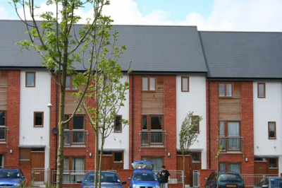
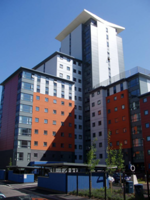
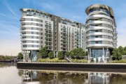
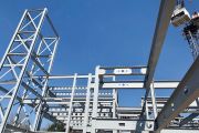
Image:Lots_Road_CW_East_Tower-3.jpg|[[Lots Road Chelsea Waterfront, East Tower]] | Image:Lots_Road_CW_East_Tower-3.jpg|[[Lots Road Chelsea Waterfront, East Tower]] | ||
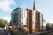
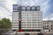
Image:Hotel_Brooklyn-1.jpg|[[Hotel Brooklyn, Leicester]] | Image:Hotel_Brooklyn-1.jpg|[[Hotel Brooklyn, Leicester]] | ||
| Line 21: | Line 17: | ||
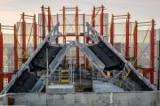
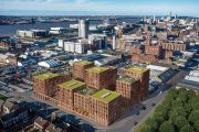
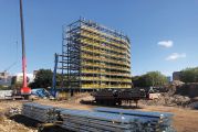
Image:One_Park_Lane_1.jpg|[[Media: One_Park_Lane.pdf| One Park Lane, Liverpool]] | Image:One_Park_Lane_1.jpg|[[Media: One_Park_Lane.pdf| One Park Lane, Liverpool]] | ||
Image:Artificial_Nesting_Structures_1.jpg|[[Media: Artificial_Nesting_Structures.pdf| Artificial Nesting Structures (ANS), Lowestoft]] | Image:Artificial_Nesting_Structures_1.jpg|[[Media: Artificial_Nesting_Structures.pdf| Artificial Nesting Structures (ANS), Lowestoft]] | ||
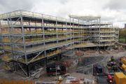
| + | Image: 325_Deansgate_hotel_1.jpg|[[Media: 325_Deansgate_hotel.pdf| 325 Deansgate hotel, Manchester]] | ||
| + | Image: Haymarket_Z.jpg|[[Media: Haymarket,_Edinburgh.pdf|Haymarket, Edinburgh]] | ||
| + | Image: Lucent_London_Z.jpg|[[Media: Lucent,_London.pdf|Lucent, London]] | ||
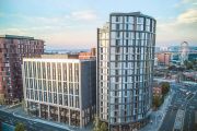
| + | Image: Paddington_Square_Z.jpg|[[Media: Paddington_Square,_London.pdf|Paddington Square, London]] | ||
</gallery> | </gallery> | ||
| Line 574: | Line 574: | ||
Image: One_Park_Lane_1.jpg|[[Media: One_Park_Lane.pdf| One Park Lane, Liverpool]] | Image: One_Park_Lane_1.jpg|[[Media: One_Park_Lane.pdf| One Park Lane, Liverpool]] | ||
Image: Artificial_Nesting_Structures_1.jpg|[[Media: Artificial_Nesting_Structures.pdf| Artificial Nesting Structures (ANS), Lowestoft]] | Image: Artificial_Nesting_Structures_1.jpg|[[Media: Artificial_Nesting_Structures.pdf| Artificial Nesting Structures (ANS), Lowestoft]] | ||
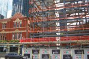
| + | Image: 325_Deansgate_hotel_1.jpg|[[Media: 325_Deansgate_hotel.pdf| 325 Deansgate hotel, Manchester]] | ||
| + | Image: Haymarket_Z.jpg|[[Media: Haymarket,_Edinburgh.pdf|Haymarket, Edinburgh]] | ||
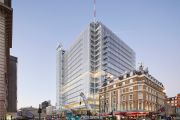
| + | Image: Lucent_London_Z.jpg|[[Media: Lucent,_London.pdf|Lucent, London]] | ||
| + | Image: Paddington_Square_Z.jpg|[[Media: Paddington_Square,_London.pdf|Paddington Square, London]] | ||
</gallery> | </gallery> | ||
Latest revision as of 23:26, 26 September 2024
The use of steel in the housing and residential building sector has grown in recent years primarily because of the growing appreciation of the performance benefits that arise from the offsite nature of the construction process, which is particularly important in urban or mixed-use buildings. Offsite steel construction technologies improve the final quality of the building and its speed of construction.
Steel is also a lightweight construction system which minimises loads on the foundations, and therefore saves on sub-structure costs, which can be important on ‘brownfield’ or infill sites or for building extensions.
The main market for steel in this sector is in multi-storey residential buildings, and particularly buildings of mixed-use, where the lower levels are for commercial use or, in some cases, for basement car parking. For mixed-use buildings, the compatibility of floor grids between the commercial, car parking and residential levels is a key factor in the design solution and is more easily achieved using steel construction. Modular or volumetric construction has also achieved a high market share in the construction of student residences and hotels, where an economy of scale in manufacture of the modules can be achieved.
A variety of steel building technologies may be used in this sector, including structural steel frames, Infill walling, floor decking, lightweight façade and roofing systems, and modular systems. There is a strong supply chain for delivery of these technologies into the residential building market.
[top]Attributes of steel construction
Main article: The case for steel
The housing and residential sector demands buildings that are energy efficient, rapid to construct and of high quality. Steel and composite construction has achieved a significant market share in the medium-rise residential sector in the UK because of the need to build quickly, particularly in urban projects. The construction process is improved, is faster and disturbance is reduced through the use of offsite manufactured steel components.
A variety of steel–based technologies may be used cost effectively in this sector, depending on the scale of the building, as follows:
- Light steel framing for housing and medium-rise residential buildings.
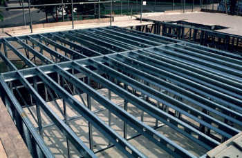
- Structural steel frames supporting either composite floor slabs or precast concrete units. This also includes Shallow floor systems
- Non-load bearing light steel infill and separating walls within steel or concrete structures
- Modular construction using fully finished 3-D units that are structurally stable as a group and can form whole buildings or parts of buildings.
The main market for steel is in multi-storey residential buildings for which its attributes of offsite manufacture, speed of construction, and light weight are maximised. This is important in large urban projects in tight infill locations or in mixed-use buildings, for example when residential units are built over a retail or commercial area. A good example of this mixed-use is in the design of modern supermarkets in urban areas, which for planning approval, often combine some residential or public use. The long span of the supermarket at ground floor level means that the upper residential levels are supported on the roof of the supermarket. Therefore reduction of loading, and achieving the required acoustic attenuation and fire resistance are key design issues affecting the design solution, which are solved by use of steel construction technologies.
Similarly, when a residential building is constructed over a car park, the column on the upper levels must take into account the efficient use of the car parking space below. This dictates the column positions as a multiple of the car park spaces, e.g. typically 5 to 5.4m and 7.5 to 8m spacing. One technique is to use Square Hollow Sections (SHS) as columns that can be designed to fit within the width of light steel separating walls in the upper residential levels.
The highest level of pre-fabrication is achieved when using modular steel systems, which have achieved a strong market share in the student residence and hotel sectors where there is an economic imperative to build fast. In the case of student residences, often the land on a university site is only released for building at the end of one academic year and the building has to be available for student accommodation at the start of the following academic year, i.e. a window of just 14 months. This dictates the whole procurement and construction process.
Similarly, in hotels, the client related benefits of speed of construction can be quantified and each month of early occupancy can be equivalent to 1% of the build cost. Many hotels are built using modular construction systems where considerable economies can be achieved by ‘economy of scale’ in the manufacturing process.
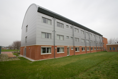
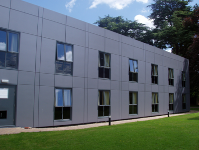
An example of this is the Aspire programme which delivered high quality accommodation for military personnel using light steel modular construction. An example of this type of modular building for military accommodation is shown.
(Image courtesy of Rollalong)
In housing, the benefits of steel construction are related to reduced cash flow and early completion of the show house and the early phases of the project, which therefore encourages sale of the later phases. The BRE SmartLife study[1] investigated four house building systems (light steel, timber, concrete and block-work) on three different sites in Cambridgeshire. The results showed that light steel systems were the fastest to construct, and had the highest site productivity and created the least waste.
The benefits of steel in residential and mixed use buildings are summarised as follows:
Speed of construction
All steel construction uses pre-fabricated components that are rapidly installed on site. Short construction periods leads to savings in site preliminaries, earlier return on investment and reduced interest charges. Speed of construction in urban residential projects is important to minimise disturbance to adjoining properties.
Flexibility and adaptability
Steel-framed systems using infill and separating walls are inherently flexible in terms of their location on plan and can be meet a variety of apartment layouts. They can be reconfigured in the future to meet new demands or even change of use. Modular systems can be dismantled and moved, thereby maintaining the asset value of the building.
Light weight
Steel structures weigh less than half of an equivalent concrete structure and light steel framing or modular systems weigh less than a quarter of a concrete structure, which saves on foundation costs, and on the supporting podium costs in a mixed-use building.
Quality and safety
Offsite prefabrication improves quality by factory controlled production, and reduces dependency on site trades and the weather. Working in a controlled, manufacturing environment is substantially safer than working on site. The use of pre-fabricated components reduces site activity for frame construction by up to 75%, thereby substantially contributing to overall construction safety.
Fire resistance
Fire safety during construction is an important consideration and one which has adversely affected timber framing. Steel construction is inherently non-combustible and does not add to the fire load.
Environmental benefits
Many of the intrinsic properties of steel usage in construction have significant environmental benefits. For example, the steel structure is 100% recyclable, repeatedly and without any degradation; the speed of construction and reduced disruption of the site gives local environmental benefits.
| Factor | Improvement | Economic benefit |
|---|---|---|
| Speed of construction | 20 to 40% reduction in construction time relative to site-intensive construction, depending on the scale of the project | The economic benefit depends on the type of project- for example, a student residence has to be delivered often within one academic year. For residential buildings, an individual apartment cannot be occupied until the building is complete and so there is an imperative for speed of construction in terms of cash flow |
| Site management costs | Site management costs are reduced because of the shorter construction period | Site management costs can be reduced by 20 to 30% which can lead to a 3 to 4% saving in terms of overall building cost |
| Minimum floor to floor height | Shallow floor systems systems have been developed to minimise the overall floor zone to as little as 400mm including a resilient floor covering and ceiling | A 5% reduction in floor to floor height can lead to one additional floor in 20, and to a similar reduction in cladding cost, which is equivalent to about 1% in total building cost. Floor to floor height often must conform to multiples of brick dimensions e.g. 2850 mm |
| Foundations | Steel construction is less than half the weight of an equivalent concrete structure, which is equivalent to a 30% reduction in overall foundation loads | Foundation costs for residential buildings represent 5 to 10% of the building cost. A 30% reduction in foundation loads can lead to a 1.5 to 3% overall saving in terms of construction cost |
| Mixed-use buildings | Long span steel construction at the podium level provides more flexible use of space below, which depends on the function of the building | The lightweight nature of the steel structure of the upper residential levels minimises the loads on the podium level and therefore saves on the cost of the podium structure |
[top]Types of residential buildings
In its simplest form, a single family house consists of one occupancy, whereas a residential building consists of multiple occupancies, in which each apartment is on one level, although duplex apartment on two levels can also be designed. The anatomy of a residential building is dependent on its size and location, and increasingly residential buildings are designed as mixed use in combination with office or retail space and car parking on the lower levels.
[top]Housing
Housing may be in three basic forms; detached, semi-detached and terrace, generally in two or three storeys. In terraced housing, floors generally span between party walls and roofs span between the front and rear façade walls. Trimmers are required around stairs in order to support the floor. In semi-detached and detached housing, the span of the floors depends on the plan form of the building. Floor spans of 3.5 to 5.5m are typical, which can be achieved using a range of steel technologies.
Modern housing in urban areas often has a relatively small footprint so that there is a benefit in building to 3 storeys, for example using a mansard type roof for habitable space. However, an important requirement of 3 storey housing is the means of escape in fire, which requires that all doors to the stairs are self-closing and have 30 minutes fire resistance.
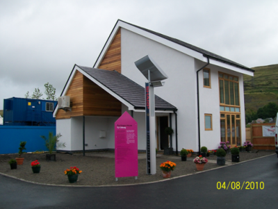
In light steel systems, relatively large openings can be created for patio doors, etc. without requiring separate lintels, which is required in blockwork walls. Curved roofs and usable roof space can also be designed. A high level of thermal efficiency can be achieved by placing the majority of the insulation outside the light steel structure to create a ‘warm frame’. U-values of less than 0.15W/m2K were achieved as in the project in South Wales (shown).
[top]Residential buildings in suburban areas
In out-of-town or suburban areas, residential buildings are often smaller (typically 3 to 5 storeys) than in urban projects, and are less constrained by the buildings around them. In this type and scale of project, the choice of facade and roofing material has to match or blend in with nearby buildings.
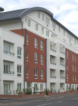
Brickwork façade walls and tiled roofs are the preferred external materials in these types of buildings. These traditional cladding materials may be supported by the internal steel structure so that the structural system is not apparent in terms of the building’s appearance. Indeed, the steel structure can enhance the appearance by permitting use of interesting features, such as large patio doors, mansard roofs, and projecting balconies.
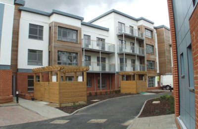
Modular construction may also be used for town houses and residential buildings of all types. The project shown uses groups of 2 and 3 modules to create each apartment of 60 to 80m2 floor area. The modules are clad in a variety of materials and steel balconies are connected to the modules.
(Image courtesy of Futureform)
[top]Residential buildings in urban areas
In urban areas, residential buildings are often complex in form in that they are often designed to fit in tight infill sites or to replace existing buildings. The nature of urban projects is also that the urban street scape has to be part of the architectural concept. Also, many sites are next to busy roads and railway lines and so questions of isolation to external noise and vibration are important design issues.
The important design requirements for urban residential buildings are:
- Structural systems that can accommodate a variable plan form and avoids obstructions or existing services in the ground
- Light weight construction systems to minimise ground works
- Fast construction systems with minimum disturbance to the neighbouring buildings
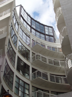
- Variety of architectural treatments, such as curved facades and roofs, and creation of private space by balconies, etc.
- Minimum floor-to-floor height to keep within planning limits for overall building height
- Street-scape created by ground floor retail units with a compatible structural grid to the residential levels above
- Safe access and use of lifts and other public space.
(Image courtesy of Vision Modular Systems)
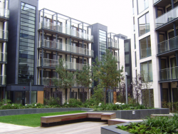
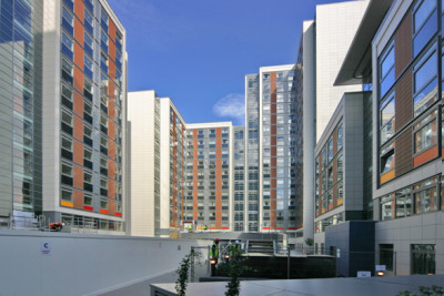
Good examples of the use of steel in urban residential projects are shown. The nature of this type of building is that floor spans are in the range of 5 to 7m, and allow for flexibility in the positioning of internal walls to optimise on the layout of the apartments. Because of this, steel shallow floor systems have proved popular because they provide a floor depth of less than 400mm, and achieve excellent acoustic insulation and fire resistance. A project in central London using a shallow floor system is shown.
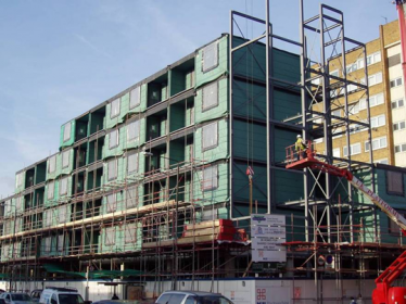
Internal and external walls may use light steel and are movable to suit the client’s and user’s demands. This can be important to housing associations who may wish to vary the accommodation that they offer depending on family sizes. Modular construction is a good solution for urban residential projects, which require extremely fast, high quality construction that is achieved by off-site manufacture. In this case, the architectural concept has to be such that the repetitive use of modules of similar size can be used efficiently. A good example of a 5 to 8 storey modular residential project in Dublin is shown.
SCI P328 gives case studies on residential buildings using steel.
[top]Mixed-use residential buildings
In urban projects, there is often a need to combine various uses in one building for example:
- Retail space at ground floor
- Office space on the lower floors
- Car parking at basement or ground floor
- Residential units on the upper floors
- Roof-top penthouses or public space.
The design issues associated with mixed-use buildings are;
- A structural grid that is compatible with the uses on the different floor levels, particularly due to the car park levels, or
- A transfer structure that allows the columns or walls on the upper levels to be different from those below
- Access to the upper levels that is independent to the lower public levels
- Effective fire resistance and compartmentation given the different fire safety measures at the various levels
- High level of acoustic insulation between the various occupancies
- Different but visually compatible architectural treatment of the public spaces and the residential space.
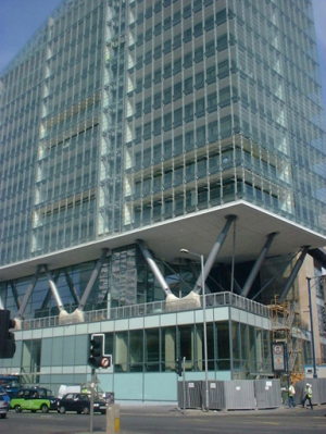
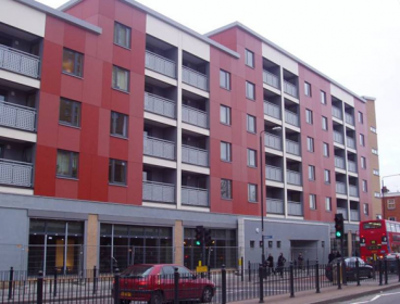
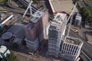
The projects shown illustrate some of these issues. A steel transfer structure can be designed efficiently, and can be part of the architectural concept. In this project in Deansgate, Manchester 16 residential floors of steel and glass are supported on inclined tubular steel columns above a public concourse and commercial space.
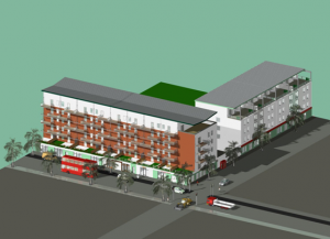
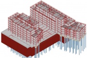
A design study of a 5-storey residential building constructed over a ground floor retail or commercial space and with below ground car parking is illustrated. The primary structure is steel frame using a shallow floor system with columns arranged on a 7.5m spacing on the facades and at a spacing internally to suit the use of the car parking level. All infill walls and separating used light steel C sections so that the space could be configured so suit the apartment layouts.
[top]Student residences
(Image courtesy of Unite Modular Solutions)
Student residences have been built in large numbers to satisfy the burgeoning demand for student accommodation, particularly in metropolitan Universities and Colleges. The nature of student residences is that en-suite study bedrooms are normally of standard dimensions – typically 2.7m wide x 6m long, and 5 or 6 rooms are served by a communal kitchen. This group of rooms is generally treated as single occupancy from an acoustic separation and fire compartmentation point of view. A double corridor is often provided so that the rooms on each side of the building are separately accessed. This means that the overall building width is typically 15m.
The construction cycle for student residential buildings is often only 12 to 14 months, i.e. June of one year to August of the next. This requires a rapid construction programme often with the constraints of nearby buildings remaining in operation during term time. A variety of steel construction technologies can be used in this sector, but the most rapid technique is achieved by modular construction, which is up to 40% faster than traditional site-intensive construction methods.
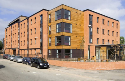
In common with other urban project, student residences often combine communal space and office space at ground floor, which can mean that the upper levels use a different structural system to that below. A good example of this is shown. In this and other similar projects, a podium level is created at first floor on which the modules are placed.
[top]Hotels
(Image courtesy of Ashorne Hill Management Centre)
For hotel projects, it is commercially imperative that they be built rapidly and to a high and repeatable quality. Typical hotel rooms are 3 to 4m wide and 5 to 6m long and are built either side of a central corridor, so that the overall building width is about 12 to 14m. The length of the ‘wing’ of the building is dependent on safe mean of escape in fire, and normally alternative fire exits are required at either end of the corridor.
A variety of steel construction systems may be used in hotels depending on the size and height. For 2 to 4 storey hotels, modular systems have been popular, especially where standard room specifications can be manufactured off-site and can achieve economy of scale in production.
A further feature of hotels in urban areas is that the ground floor is used for a restaurant and lobby and sometimes retail outlets, so that the bedrooms on the upper levels are constructed on a ground floor podium similar to other mixed-use buildings.
[top]Forms of construction
Main articles: Composite construction, Floor systems, Long-span beams, Infill walling, Modular construction
Various forms of steel construction may be used in housing and residential buildings, depending on their size and complexity. These are described below;
[top]Light steel framing
Light steel framing consists of C sections that are cold roll-formed from galvanised steel strip of 1.2 to 2.4mm thickness. The C sections are placed at 400 or 600mm spacing to be compatible with plasterboard dimensions, and are typically:
- 75, 100 or 150mm deep for load-bearing walls
- 150, 200, 250 or 300 mm deep for floor joists.
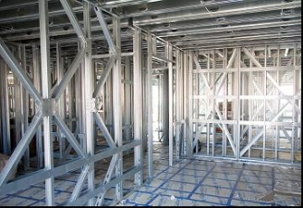
Light steel frame walls are manufactured as storey-high panels and 2.4 to 4m width and support the floors directly by use a Z section over the wall. This is normally 2mm thick and also acts a lintel over openings. The walls can resist vertical loads up to 100kN/m as a line load, typical of their use in a 7 storey building. The walls are braced to resist horizontal loading, and bracing may be in the form of integral K or W bracing using C sections or X bracing using flat strip.
Floor joists can be installed as individual sections or as part of a pre-fabricated floor cassette. Spans of 3.5 to 6m can be designed with joists normally at 400mm spacing. Lattice joists may be used for longer spans.
Single span, simply supported floors consisting of 150mm deep composite floor slabs may also be carried by the light steel walls, where a very thin floor is required. Such floors are supported by the Z section over the walls and spans of up to 5m are possible. For the purposes of fire resistance, rebar is required in the deck trough.
Integral K- and X-bracing in light steel walls
(Image courtesy of Fusion Building Systems)
Guidance on the design of light steel construction in residential buildings is given in SCI P402.
[top]Steel frames with light steel infill walls
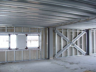
A variety of structural steel systems may be used in residential buildings. The structural system consists of beams and columns on a regular grid on each floor, in which the floor spans between the beams. The floor slab may be in the form of in-situ concrete placed on steel decking or alternatively precast concrete units. The façade and internal walls comprise light steel infill and separating walls and they allow the internal space to be configured to meet the architectural requirements.
Further information on multi-storey residential buildings using steel is available in SCI P329 and SCI P332.
[top]Composite beam and composite floor slabs
Composite construction consists of downstand I-section steel beams with shear connectors (studs) welded to the top flange to enable the beam to act compositely with an in-situ composite floor slab. In residential buildings, the beams are usually chosen to be shallow (such as 203, 254 or 305 UC sections) so that the overall floor depth is less than 500mm. The maximum span of these beams is normally about 30 times their depth (therefore up to 9m), which is within the range of application in residential buildings.
Columns are often in the form of Square or Rectangular Hollow Sections that fit within separating walls. Typical sections are 100x100, 150x150, 200x100 or 200x150 SHS, depending on the wall width.
The composite slab comprises profiled steel decking of various shapes that span 3 to 4m between secondary beams. Composite floor slabs are typically 130 mm to 150mm deep in residential buildings, depending on the deck height.
The profiled steel decking supports the wet weight of the concrete and construction loading. Sufficient composite action occurs between the decking and concrete so that it is generally the construction condition that controls the maximum spans that can be achieved. Where the decking is propped during construction, longer spans can be achieved but the span: depth ratio of the slab is limited to about 28 so that the serviceability performance of the floor is acceptable.
[top]Steel beams and precast concrete slabs
In the residential sector, precast concrete slabs are often used, and they may be supported on steel beams that align with the walls so that they do not project into the room space. The precast concrete slabs may be designed to act compositely with the steel beams and if so, the steel beams must be at least 190mm wide to provide support to the precast units and to allow sufficient space around the shear connectors. Often UC sections are used as the supporting beams to minimise the overall floor depth. A typical use of precast concrete slabs on a steel frame is shown.
[top]Shallow floor systems
(Image courtesy of Kloeckner Metals UK Westok)
Shallow floors offer a range of benefits such as minimising the overall height of a building for a given number of floors, or maximising the number of floors for a given height of building. Additionally, a flat soffit is achieved - there are none of the interruptions found with downstand beams - which gives complete freedom for the distribution of services below the floor. These benefits should be considered in the context of a given project to identify when they are most appropriate.
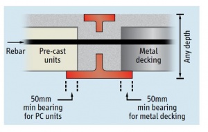
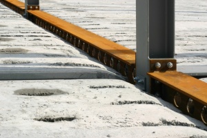
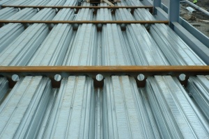
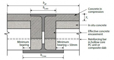
The shallowness of the floors is achieved by placing the slabs and beams within the same zone. This is achieved by using asymmetric steel beams with a wider bottom than top flange, which enables the slab to sit on the upper surface of the bottom flange with adequate bearing, rather than the upper surface of the top flange as found with downstand beams. The floor slab may be in the form of a precast concrete slab or a composite slab with metal decking (either shallow or deep decking may be used). An added benefit is that some forms of shallow floor construction inherently achieve composite interaction between the beams and slab, thereby enhancing structural efficiency.
A number of shallow floor solutions are available, including Ultra Shallow Floor Beams (USFB) from Kloeckner Metals UK Westok.
Kloeckner Metals UK Westok’s USFB system comprises a shallow and asymmetric Westok cellular beam with reinforcement placed through the cells to anchor the slab to the beam. This simple detail provides a straightforward and cost-effective arrangement to prevent disproportionate collapse and is also used to resist torsion in the final condition. For composite slabs with metal decking the reinforcement is placed in the troughs of the metal decking. With hollowcore slabs, the reinforcement is placed in alternative cores of the precast unit. To restrain the top flange of the USFB in the Normal Stage, the insitu concrete should be cast flush with, or with at least 30 mm cover over, the top flange.
The USFB is manufactured from standard rolled sections, and is available in increments of 1 mm depth. They are typically 150-300 mm deep and are sized and designed using Westok’s freely available Cellbeam software package based on each individual project requirements and floor grids etc. The software carries out all of the necessary structural checks, including torsion checks in the Construction Stage. USFBs can economically span up to 10 m with structural depths that compare very favourably with R.C. flat slabs. As such, they are popular in many sectors including Residential.
‘Plug Composite Action’ can be mobilised for USFBs, which has been demonstrated using full-scale laboratory testing, to further enhance the capacity of the section. To mobilise ‘Plug Composite Action’, the following detailing should be adopted:
- Composite slabs with metal decking: Concrete cast level with, or above, the top flange
- Precast units generally: Minimum 50 mm topping level with, or above the top flange
- Hollowcore units: Every 2nd core broken out and filled with concrete and reinforced through the cell
- Solid in-situ slabs: Concrete cast level with (or above) the top flange
[top]Infill walling
In residential buildings, light steel walls are widely used, both as infill walling at the facade and as internal separating walls. A typical example of infill walling used shallow floor construction is shown. For floor-to-floor heights of up to 3m, the C sections are generally 100mm deep and are placed at 600mm spacing. A variety of cladding materials may be supported by the infill walls.
[top]Modular construction
(Image courtesy of Caledonian Building Systems)
Modular construction consists of 3-D or volumetric units that are generally of room size, and a group of modules can be arranged to provide a stable building form. Modules are typically 2.7 to 4m wide and 6 to 12m long, and are designed to be load-bearing, either through their side walls or through corner posts and edge beams. They can be designed to resist horizontal loads for buildings up to about 6 storeys high. For taller buildings, an additional braced core or in some cases, a concrete core is used to provide stability to the group of modules.
The modules are tied together at their corners so that loads can be transferred between them both in normal conditions and in extreme cases of loss of support from below (called ‘structural integrity’ or ‘robustness’ in the Building Regulations).
The main feature of modular buildings is the economy that results from the repetitive use of similar sized elements, such as in hotels and student residences. The corridors and circulation space is generally constructed from planar elements, but large modules can also be designed to incorporate a central corridor.
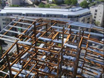
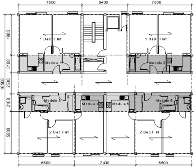
It is also possible to optimise the use of modular construction in steel framed buildings by designing the modules to incorporate only the highly serviced parts of the building such as bathrooms and kitchens. Modules can be supported by shallow UC or shallow floor beams so that the overall floor depth is minimised. A typical plan form of a mixed modular and steel framed structure is shown.
More guidance on design using modular construction is given in SCI P302.
[top]Podium structures
Podium structures can be designed in steel to support another form of structure above. A podium is often known as a transfer structure where the column grids above and below are different. A good example of this is when a residential building is located over commercial space or car parking. The transfer structure is designed to support the weight of the building above. Load bearing walls or columns are positioned so that they are supported by the steel beams of the transfer structure.
An example of a modular residential building for a housing association is shown, in which the modules are supported on a first floor podium with ground floor offices below. The beams in the podium level align with the side walls of the modules. The braced steel structure also provides the access and circulation space and provides stability to the upper levels. The modules are also constructed with integral balconies.
- Modular building supported on a first floor podium, East London
For car parking below podium level, columns should align with multiples of car park spaces, i.e. a multiple of 2.5 to 2.7m and in the other direction should be on a 4.5m, 7.5m and 4.5m grid. In some cases, a 16m clear span supporting steel structure can be designed to provide more flexible use of the space below. Long-span cellular or fabricated beams may be used efficiently if the residential levels above are sufficiently lightweight to be supported by these beams. The beam depth may be taken as typically span/20 or around 800mm for a 16m span.
The most efficient use of podium type structures is in mixed-use buildings with 4 to 6 levels of residential use above 2 storeys of commercial use. The upper levels should have a separate entrance area and means of escape in fire, which often leads to use of multiple braced steel or concrete cores, which can be designed to provide stability to the super-structure.
Other functional requirements for podium structures are fire resistance and structural integrity as key elements, and distribution of services and pipes from the upper levels. The long-span beams at podium level are often perforated with large web openings to allow the services to be distributed horizontally.
[top]Key issues in the design of residential buildings
Main articles: Cost of structural steelwork, Cost planning through design stages, Sustainability
[top]Procurement
Procurement in the residential building sector is generally contractor or developer-led. An architect employed by the developer would first prepare the scheme drawings for planning approval, which would include the materials to be used in the facade and roof but not necessarily in the primary structure. For medium–rise buildings, solutions in concrete, steel or timber would be equally feasible at this stage of the scheme design.
Having gained planning approval on a scheme layout, the detailed design would be carried out to the level required for competitive tendering by a main contractor. The chosen contractor’s tender would be based on a form of construction that is most cost-effective for the particular project and location, which would depend on issues such as site logistics, availability of suitable sub-contractors, minimum ground and temporary works, etc.
Steel technologies would be considered strongly at this stage because they are procured through specialist sub-contractors with a proven track record, and are installed rapidly on site with minimum contractual risk. The design of the light steel structure is carried out by the specialist supplier and coordinated with the overall building design. The specialist supplier would generally carry out the site installation.
A recent important innovation is that of Building Information Management (BIM) systems in which the design team, contractor and specialist suppliers share in a common design and drawing system. Steel systems of all types are designed and detailed by compatible software that is used in the manufacturing process and can be incorporated into the BIM system easily.
[top]Building economics
The economics of private housing and residential building is dependent on the market conditions and saleability of the properties. Mixed-use buildings would also include commercial space which would lead to further income. In the social housing sector, housing associations take a longer term view of the overall building economics, which would include issues such as maintenance, design life, and flexibility in use to meet future housing needs.
The approximate breakdown of total build cost for a multi-storey residential building is as follows:
- Foundations 5 to 12%
- Super-structure and floors 15 to 20%
- Cladding and roofing 20 to 25%
- Windows and doors 10 to 15%
- Services (mechanical , electrical & lifts) 15 to 20%
- Services (sanitation and water) 5 to 8%
- Finishes and fitments 20 to 25%
- Site management (preliminaries) 10 to 15%
Preliminaries represent the costs of the site management and on-site facilities, including hire of cranes, storage space and equipment. Site preliminaries can vary with the scale of the project, and a figure of 15% of the total cost is often allowed for site-intensive residential construction reducing to 10% for projects involving higher levels of off-site prefabrication, such as steel construction. Further cost information is available here.
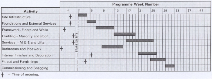
[top]Construction programme
Speed of construction is very important in housing and residential buildings projects in order to reduce cash flow and to minimise disturbance to the nearby properties. The construction programme for a typical residential building project is presented below:
[top]Sustainability
In the context of housing and residential buildings, the principal sustainability issues to address include how to minimise operational energy use, particularly in the heating, and lighting systems and any specific planning requirements for renewable energy systems.
Information on the sustainability of steel in housing and residential buildings is available in SCI P370.
Guidance on the design of sustainable mixed-use buildings is given in the Target Zero design guide on mixed-use buildings.
[top]Thermal performance
The thermal performance of residential buildings depends primarily on the strategies necessary to achieve the Target Primary Energy Rate, the Target Emissions Rate (TER) and the Target Fabric Energy Efficiency (TFEE) set under Part L Volume 1: 2021[2] of the Building Regulations.
The Target Primary Energy Rate is use of energy per square meter of floor area per year. The TER is expressed as the mass of CO2 emitted in kilograms per square meter of floor area per year. The TFEE rate, which is a target introduced in 2013 for new dwellings only, is expressed as the amount of energy demand in kilowatt-hours per square metre of floor area per year. The TER and TFEE rate for individual dwellings must be calculated using SAP 10.2.
In addition, Approved Document L1[2], includes:
- Limits on design flexibility including limiting fabric standards and limiting services efficiencies
- Maximum allowable airtightness
- Limits on the effects of heat gains in summer and heat losses in winter
- Ensuring that fixed building services meet specified efficiency requirements
- Ensuring the quality of construction and commissioning of fixed building services
- Provision of information on the operation and maintenance of fixed building services to building owners
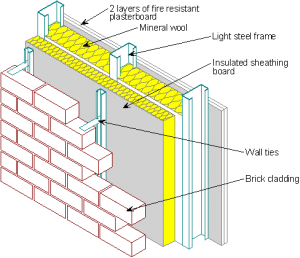
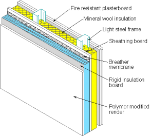
In light steel structures and infill walls, the required level of thermal insulation is achieved by ‘warm frame’ construction in which the majority of insulation is placed outside the steel elements, as shown for brick and insulated render cladding. Mineral wool is also placed between the C sections, but this is combined with 70 to 150mm of closed cell insulation board external to the frame.
- Typical light steel 'warm frame' construction
Brick wall attached to light steel framing
Insulated render attached to light steel framing
The table shows the typical thickness of external insulation in to achieve given U-values. Two types of insulation board externally are considered; PIR (Polyisocyanurate) closed cell insulation for brickwork facades and PIR or EPS (Expanded Polystyrene) insulation for insulated render facades.
| U-value of wall (Wm-2K-1) | Brickwork facade | Insulated render facade | |||
|---|---|---|---|---|---|
| PIR thickness (mm) | Overall wall depth (mm) | PIR thickness (mm) | EPS thickness (mm) | Overall wall depth (EPS) (mm) | |
| 0.25 | 50 | 315 | 50 | 60 | 210 |
| 0.22 | 80 | 345 | 60 | 80 | 230 |
| 0.20 | 100 | 365 | 80 | 100 | 250 |
| 0.18 | 120 | 385 | 90 | 120 | 270 |
| 0.15 | 150 | 405 | 110 | 150 | 300 |
Thermal bridging that is associated with linear and point effects on the building envelope are known as ’non-repeating thermal bridges’. Thermal bridging should ideally not add more than 20% to the overall heat loss through the building envelope.
In housing and residential buildings, air leakage of warm air and hence air infiltration of cold air, can account for over 30% of heat loss from the building and should be controlled. Standard air-tightness testing involves large fans imposing an internal pressure of 50 Pa within the building. For residential buildings, the air infiltration that is used in whole building energy calculations is taken as 5% of the value.
Typical air-tightness data for light steel and modular housing and residential buildings is presented in the table . Improved air-tightness can be achieved by use of an external sheathing board or by vapour check plasterboard.
| Air permeability target (m3/m2/hr) | Light Steel Framing and Steel Structures with Infill Walls | Modular Construction |
|---|---|---|
| < 10 | Normal construction practice for a planar construction with no special measures for air-tightness | Modular construction achieves improved air-tightness due to its off-site manufacture - see below |
| < 7 | Seal joints and gaps at top and bottom of walls using acoustic sealant. Seal external insulation boards. Use ‘socket pads’ to seal around these service penetrations | Air-tightness of 7 m3/m2/hr is achievable due to precise cutting of boards and sealants at junctions in the module manufacture |
| < 5 | Use of external sheathing boards plus the above measures. Vapour check plasterboards may be used internally. Use sleeves around pipes at the airing cupboard to roof space junction | Use external rigid sheathing boards or double layers of plasterboards internally, plus the above measures in quality controlled manufacture |
| < 3 | Special measures including one or more techniques:
|
Achievable with rigid sheathing boards and sealing around all service penetrations (due to the cellular nature of modular construction) |
| < 2 | An impermeable continuous membrane may be required to achieve minimum air leakage | As for planar construction, but the performance is more reliable and less dependent on site installation |
Condensation is a phenomenon where warm moist air condenses on cold surfaces. This effect is minimised by ensuring that cold spots on the internal surface of the building are within limits (normally 10% of the temperature of the rest of the wall). Where there is a risk of condensation within the cladding itself, a vapour tight membrane may be placed on the inside of the building. This should be supplemented by effective and controlled ventilation of the internal space. Use installed with foil-backed plasterboard or with a separate membrane in rooms with a high humidity environment.
Information on energy efficient housing using light steel framing can be found in SCI P367.
[top]Renewable energy systems
The most common renewable energy technologies that may be found in housing and residential buildings include:
- Photovoltaic (PV) panels attached to the roof
- Solar thermal hot water panels attached to the roof
- Ground or air-sourced heat pumps
- Small-scale wind turbines
- Combined heat and power (CHP, which may be suitable for larger projects)
- Biomass heating and hot water distribution (suitable for social housing).
The relative merits of each system depend on the type and scale of the housing or residential project. PV and solar thermal panels are now conventional technologies which can be easily attached to light steel roofs.
For larger residential buildings, CHP and biomass systems require a more complex energy and maintenance strategy, which is best managed by the building owner such as a housing association. The excess heat produced by CHP can also be used for swimming pools or distributed as part of the district heating system.
[top]Floor zones
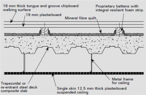
The overall floor zone includes the structural elements, e.g. beams and slab, the acoustic floor system, services zone and the ceiling. The acoustic floor system is common to all forms of construction and consists of battens, resilient layer and boarding, or alternative a mineral wool layer on which the boarding is placed. Its primary function is to reduce impact sound transmission.
In housing, the plasterboard is either directly fixed to the floor joists or indirectly via resilient bars fixed to the joists. An overall floor zone of 450mm is normally allowed in housing which leads to a floor-to- floor height of 2850mm which is compatible with multiples of brick dimensions.
In residential buildings, the plasterboard ceiling is suspended below the beams and floor slab. A horizontal service zone is created, or the steel beams can be perforated by web openings (usually in the form of fabricated or cellular beams) which allows ducts to be distributed throughout the building. Shallow floor systems can also be used to provide an uninterrupted zone for services. An overall floor zone of 450 to 600mm is normally allowed in residential buildings. A depth of 450mm is possible using such shallow floor systems.
[top]Below ground car parking
The design issues to be addressed in below ground car parking are:
- Compatibility of column grid with the super-structure
- Fire resistance requirements, including effective ventilation of any fire that may occur
- Retaining walls around the perimeter of the car park area
- Vehicular access via a ramp from street level
- Access to the upper levels
- Protection to the columns against impact.
Below ground car parking can be achieved using column positions as follows:
- Longitudinal spacing of 5 to 5.4m for 2 car parking spaces, or 7.5 to 8m for 3 car parking spaces between the columns
- Transverse spacing of 4.5m, 7.5m and 4.5m across the building to allow for a central access aisle and turning arc into the car parking spaces.
For podium type structures, it is possible for clear spans of 16.5m using long-span steel beams over the car parking areas at ground or basement level.
[top]Service integration
In steel-framed residential buildings, web openings in beams provide space for ducts to extract stale and moist air from internal bathrooms and kitchens. Because of the need to minimise the overall floor zone in residential buildings, beams are often relatively shallow at 250 to 350mm deep and so service openings are 150 to 200mm deep.
Shallow floor construction has proved popular in the residential sector because an uninterrupted service zone is created under the beams, which leads to an overall structure and service zone of less than 600mm, and often as low as 450mm.
With light steel framing construction, a service zone is provided under the ceiling so that the fire protection function of the plasterboard is not affected by the horizontal ducts. Also, vertical ducts through the floor or floor slab have to be fire protected to prevent passage of smoke or flame in a potential fire.
[top]Fire safety
Fire safety is very important in residential buildings and is characterised by:
- Safe means of escape in the event of a fire, involving alternative escape routes and fire protected lobbies, etc.
- Measures to control the risk and severity of the fire, such as smoke detectors and sprinklers
- Fire doors to prevent passage of smoke
- Effective compartmentation of dwellings through the walls, floors and service ducts
- Suitable periods of fire resistance to permit effective fire fighting and to avoid premature structural collapse.
The following table presents the typical thickness and number of boards required for light steel walls and floors for fire by the use of fire resistant plasterboard (known as type F to BS EN 520[3]).
The table also provides guidance on the design of composite slabs used in residential buildings. Their behaviour in fire is dependent on whether they are designed as simply supported or continuous. For simply supported slabs, additional bar reinforcement is generally required in the ribs of the decking.
| Fire resistance (mins) | Load-bearing walls | Infill walls | Suspended floors | Composite floors |
|---|---|---|---|---|
| 30 | 1 x 12.5mm | 1 x 12.5mm | 1 x 12.5mm | Not required, except for acoustic performance |
| 60 | 1 x 15mm | 1 x 12.5mm | 2 x 12.5 mm | A142 mesh for continuous slabs. 12mm dia. bar reinforcement for simply supported slabs |
| 90 | 2 x 15mm | 2 x 12.5mm | 3 x 12.5mm | A193 mesh for continuous slabs. 16mm dia. bar reinforcement for simply supported slabs |
| 120 | 3 x 15mm | 2 x 15mm | 3 x 15mm | A252 mesh for continuous slabs or 16mm dia. bar reinforcement for simply supported slabs plus 15mm ceiling board |
[top]Floor vibrations
The control of floor vibrations is achieved by two methods, based on a minimum natural frequency, or for vibration sensitive cases, a response factor method in which the likely accelerations due to walking or rhythmic activities is calculated. General guidance for residential buildings is presented below:
- The stiffness of the floor should be such that its fundamental vibration frequency (natural frequency) exceeds the likely vibration excitation (normally walking) by a factor of 3. For a footfall of two steps per second, a natural frequency of more than 6Hz generally ensures minimal vibration response
- For lightweight floors, the lower limit on natural frequency is increased to 8Hz for rooms of residential buildings and 10Hz for corridors and communal areas
- For open plan areas in residential buildings, or for areas where there may be rhythmic activities, a more appropriate method is the response factor approach which is based on the level of the vibration, measured in terms of acceleration
Further guidance is available in SCI P354. The Steel Construction: Floor Vibration publication is also relevant, and a useful web-based Floor response calculator is also available to swiftly evaluate the vibration response of floors.
[top]Acoustic performance
The acoustic requirements of residential buildings are such that the floors must provide a vertical acoustic separating and fire resisting function, as must internal walls between individual apartments. In housing, there are no requirements for sound reduction within an individual dwelling, but the ‘party’ wall or separating wall between dwellings in semi-detached or terraced housing has an acoustic separation and fire resisting function.
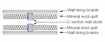
Approved Document E[4] specifies the minimum levels of airborne sound reduction between dwellings, which is defined by a parameter DnT,w combined with a low frequency correction factor, Ctr. The minimum DnT,w +Ctr limt is 45dB for tests on new dwellings. In addition, for floors, a maximum impact sound transmission limit is also specified, which is generally satisfied by using a resilient floor layer. The following figures show the typical acoustic build-ups in floors and walls for light steel framing and for composite floor construction. More information is given in SCI P320, SCI P336 and SCI P372.
- Details to provide acoustic insulation of light steel walls and floors
Click here for further information
Click here for further information
[top]Health and safety
Modern steel construction in the residential building sector ensures a high level of health and safety during construction because:
- Safety barriers and edge protection can be provided as part of the steelwork package
- Floor decking and light steel infill walling is delivered cut to exact length so that little cutting is required on site.
- Light steel framing is manufactured accurately and is relatively easy to handle on site and is fixed using hand tools. No cutting is required.
- Modular units are installed by crane and are stable when stacked. Little manual labour is required on sites using modular construction.
[top]Corrosion protection
Modern steel frames within heated buildings do not generally require protection against corrosion. Steel decking and light steel infill walls use galvanised steel and so are protected against corrosion in an internal atmosphere. The zinc coating provides passive protection. In infill walls, the light steel components, which are also galvanised, are weather protected by the cladding system and by the external insulation.
In light steel framing, monitoring studies of 20 years have shown that the rate of zinc loss, is less than 0.5g/m2 per year which is commensurate with a design life of over 200 years. Guidance is presented in SCI P262.
[top]Fabrication and construction
Some features of modern steel fabrication and construction relevant to multi-storey residential buildings are as follows:
- For primary steel frames, the fabrication processes are similar to the multi-storey commercial sector. UC sections are often used for beams to minimise the floor depth.
- Most residential buildings are designed as braced by X or K bracing, although buildings up to 4 storeys high can be designed for stability by using moment resisting end plates to connect the structure.
- Shallow floor systems using asymmetric beams are widely used in the residential sector and require use of end plate connections to resist torsional effects acting on them during construction.
- Square Hollow Section columns of up to 150mm size are often used to fit within separating walls.
Best practice in the construction of steel-framed residential buildings is available in SCI EP36.
[top]Typical details
Main articles: Simple connections, Moment resisting connections, Building envelopes, Facades and interfaces
The following typical details may be considered, depending on the forms of construction
- For light steel framing, floors are supported by walls and so these details are the most important in terms of stability and robustness. The walls are braced to provide the overall stability of the building
- For structural steel frames, beams are connected to columns using bolted end plates, which provide some stiffness to reduce deflections. However, vertical bracing is required to provide overall stability.
- Modular systems are tied at their corners by steel plates and single bolts.
[top]Connections in light steel framing
Connections in light steel framing are generally made by self-drilling, self-tapping screws of 4 to 5mm diameter, and their shear resistance is about 3 kN per mm thickness of steel connected. Therefore multiple screws (often 6 to 8) are required in the key connections, such as X- bracing. Connections should be designed to act in sheer rather than tension as pull-out resistances are lower than (typically half of) shear resistances.
For robustness purposes, additional ties in the form of straps may be required, particularly when SHS posts are incorporated in light steel walls.
[top]Connections in steel framed buildings
Structural steel frames used in residential buildings are generally designed to be vertically braced in which case, the connections are designed as ‘simple’, i.e. shear resisting. However, for 3 or 4 storey buildings, it is possible to design moment-resisting connections using extended end plates to steel beams.
If SHS columns are used, then the connections of beams to these may be made by extending the end plates outside the column width or by welding T sections to the face of the SHS.
[top]Infill walls
In steel-framed residential buildings, light steel infill walls are used to provide resistance to wind action on the façade and also to achieve the required thermal performance characteristics.
A particular requirement of infill walls is that should provide for relative movement with respect to the supporting structure and a minimum of 10mm is allowed in steel-framed buildings depending on the span of the edge beams (up to 6m in this case).
[top]Building envelopes
The building envelope of steel framed residential buildings comprises the facade and roof elements with other features, such as balconies and parapets, which can be created easily using steel construction.
[top]Façade systems
Cladding systems to light steel infill walls or to light steel load-bearing structures are similar and fall into three generic categories:
- Brickwork that may be ground supported or supported on steel beams at each floor
- Insulated render bonded to a sheathing board that is fixed to the light steel walls
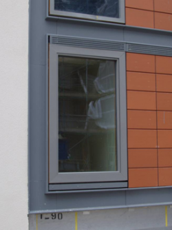
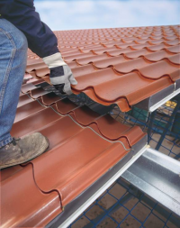
- Tiled or rain screen system attached to horizontal rails that are screw fixed through the external insulation to a sheathing board
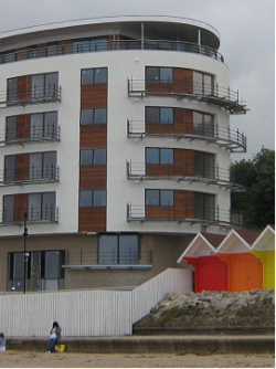
Examples of these forms of cladding system used on light steel residential buildings are shown below. Curved facades can be created by faceting the light steel walls.
Curved façade using insulated render attached to light steel framing
(Image courtesy of Metsec Framing Ltd.)Insulated render attached to light steel infill walls
Information on insulated render systems used with light steel framing is available in SCI P343.
[top]Roofing systems
For housing, roofs are normally in the form of traditional, tiles that are supported on battens that span between the roof trusses at 600mm centres. Where habitable space is required, open roof systems may be created by:
- Light steel open roof systems of the form shown
- Purlins spanning between cross-walls.
For residential buildings, light weight roofing systems, such as composite panels are more often used. Mansard shaped roofs can be created in light steel framing.
[top]Balcony systems
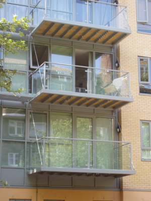
There are various generic forms of balcony systems:
- Balconies tied back to the floors
- Cantilever balconies from the columns or additional steel posts
- Ground supported balconies
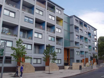
- Balconies that are inside the façade line of the building, as is the case often for modular buildings.
All balcony systems are made from steel usually in the form of C sections. Two examples of balcony systems in residential buildings are shown.
In the project shown, the modules were manufactured with their facade walls on alternate modules set back to create balcony space for a single bedroom apartment consisting of two 30m2 modules.
(Image courtesy of Alford Hall Monaghan Architects and Yorkon)
[top]Case studies
[top]References
- ↑ SmartLIFE - Lessons Learned. BRE Press, 2008
- ↑ 2.0 2.1 Approved Document L1, 2021, Conservation of fuel and power, Volume 1: Dwellings. Department for Levelling Up, Housing and Communities
- ↑ BS EN 520:2004+A1:2009 Gypsum plasterboards. Definitions, requirements and test methods. BSI
- ↑ Approved Document E (Resistance to the passage of sound) 2003 Edition incorporating 2004, 2010, 2013 and 2015 amendments. Ministry of Housing, Communities & Local Government
[top]Resources
- SCI P262 Durability of Light Steel Framing in Residential Building. Second edition
- SCI P301 Building design using cold formed steel sections: Light steel framing in residential buildings
- SCI P302 Modular construction using light steel framing – Design of residential buildings
- SCI P320 Acoustic performance of light steel framed systems
- SCI P328 Case studies on residential buildings using steel
- SCI P329 Multi-storey residential buildings using steel: Steel technologies to meet new housing demands
- SCI P332 Steel in multi-storey residential buildings
- SCI P336 Acoustic detailing for multi-storey residential buildings
- SCI P343 Insulated render systems used with light steel framing
- SCI P354 Design of Floors for Vibrations- A New Approach
- SCI P367 Energy efficient housing using light steel framing
- SCI P370 Sustainability of steel in housing and residential buildings
- SCI P372 Acoustic detailing for steel construction
- SCI EP36 Best Practice in Steel Construction: Residential Buildings
- SCI P402 Light steel framing in residential consrtuction
- Target Zero: Guidance on the Design and Construction of Sustainable Low carbon Mixed-Use Buildings
- Steel Construction: Floor Vibration, BCSA, 2016
- Floor response calculator
- Costing Steelwork 5 – Residential / Mixed-use Buildings, April 2018
[top]See also
- Floor systems
- Car parks
- Thermal performance
- Modular construction
- Service integration
- Fire and steel construction
- Acoustics
- Floor vibrations
- Building envelopes
- Infill walling
- Facades and interfaces


