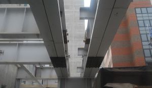
Vine Street student accommodation, London
Article in NSC November 2019
History lesson
The need to preserve and exhibit Roman remains has dictated the design and configuration of a steel transfer structure that supports a new student accommodation block in London.
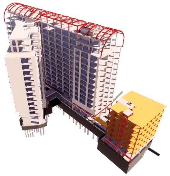
Tucked behind Fenchurch Street railway station in the City of London, a new student accommodation-led mixed-use scheme is quickly taking shape, thanks to the support and spanning qualities of structural steelwork. The project consists of four towers, three of which are concrete-framed and reach heights of between 14-storeys and 12-storeys, while a fourth is a steel-framed six-storey structure (see below).
The latest scheme from Urbanest, a developer and operator of student accommodation, the project will provide 654 student beds, alongside 5,500m2 of Grade-A offices and space for start-up businesses. Urbanest describes the project as its most ambitious scheme to date and all of the beds are to be offered exclusively to students from King’s College London, through a long-term nominations agreement.
Another aspect of the scheme will be the inclusion of a three-storey museum that will exhibit some previously concealed remains of a bastion tower and part of the 4th Century wall that once encircled Roman London. These archaeological remains, which are set to be made readily accessible to the public, were the main driver for the design of a large steel structure, as Robert Bird Group Engineer Liam Guntrip explains. “In order to span 17.5m over the wall, create sufficient internal space for the museum and other facilities, while also supporting an accommodation block above, we opted to design a large steel transfer structure. After considering concrete options we found steelwork provided the most buildable design. Concrete construction would have been problematical due to the difficulty of forming concrete over the Roman wall.”
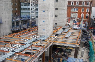
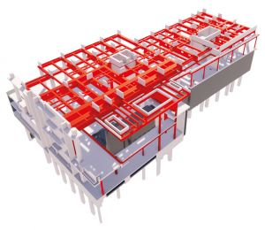
Measuring approximately 50m × 20m, the deck is 10m-high and accommodates two basement levels and a ground floor, while supporting a 14-storey student accommodation block above. Split into two distinct parts, the transfer structure encompasses two cores that will serve the accommodation tower, while also providing the steelwork with some stability.
The northern section, that spans the Roman remains will accommodate a three-storey gallery and museum with an underground public viewing platform, café and exhibition space. The southern half of the steel transfer structure also contains some long spans and will accommodate a ground floor student reception area fronting Vine Street, and two basement levels containing space for entrepreneurial start-up businesses, and back-of-house facilities such as bicycle storage areas and a loading bay.
Prior to the steelwork erection beginning, main contractor Balfour Beatty had already encased the Roman remains in order to prevent any damage during the construction programme. “We also tweaked the connection design of the steelwork beams that span the Roman remains, so all of the bolts could be tightened from outside of the sensitive area,” explains Bourne Steel Divisional Manager Andy Davies.
To create the column-free space over the remains, two parallel 17.5m-long girders have been installed at first floor level. As they are positioned in the middle of the transfer structure at the furthest point from any vehicular access point, there was a need to redesign these members in order to limit the size of crane needed to lift them into place. The girders are consequently formed from channels, which were spliced together in-situ, to form a 25t section. There are eight 1,850mm-deep pieces in total; four needed to complete each girder.
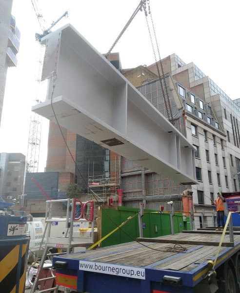
A 500t-capacity mobile crane, which required a road closure, was needed to install these large girders. To minimise disruption, Bourne Steel’s erection programme for the initial phase was completed in just one weekend. This consisted of nine truckloads of steelwork, with the heaviest member being over 22t and measuring 13m-long × 1.8m-deep with 120mm thick flanges and 45mm thick webs. “To coordinate nine deliveries over one weekend was always going to be a challenge, but we had an excellent team and successfully installed 180t of steelwork. We even had time for Balfour Beatty and our team to sign off the largest plate girder, which sits encapsulated above the Roman wall,” adds Mr Davies. “However, this wasn’t the project’s largest member, this was a beam that was over 20m-long x 1.25m-deep with 80mm thick flanges and 50mm thick webs, weighing 27t. This plate girder was installed using a smaller 250t-capacity crane.”
The steel deck supports a 14-storey block and connects to a six-storey steel-framed structure
Bourne Steel unloads the project's largest plate girder
As well as providing the required long internal spans, the transfer structure will also support 14-storeys of student accommodation. In order to have sufficient strength and robustness, the structure’s columns are all plated 356 x 406 x 467 sections. Bourne Steel completed the transfer structure in September, allowing the project team to start constructing the student accommodation block above.
Summing up, Balfour Beatty Project Manager Andy Cross says: “Engaging Bourne at an early stage in the project enabled us to create a robust strategy for delivering this challenging aspect of project works. Regular stakeholder consultation, meticulous planning, and coordination of programmed works, in collaboration with our supply chain, ensured a well-executed delivery, finishing ahead of schedule and mitigating any disruptions to local residents or businesses. The feedback has all been extremely positive.”
The entire project is targeting a BREEAM ‘Excellent’ rating upon scheduled completion in 2021.
Light frame construction
The overall project also includes a steel-framed six-storey student accommodation block that sits adjacent to the transfer structure and has an entrance on Crosswall.
Joined by a covered walkway, the two steel structures are both structurally independent, while the design of the accommodation block has also been driven by Roman remains.
“The block has been designed to infill an area between two existing buildings, it also has a lightweight frame because we could not install piles as there are further remnants of the Roman wall beneath its footprint,” explains Robert Bird Group Engineer Liam Guntrip.
Consequently, to keep the building’s weight to a minimum, it will be constructed on shallow raft foundations and will then utilise a steel frame with lightweight Metsec joists supporting a plywood floor.
Erected around a single stability-giving concrete core, the steel frame will have a 5m × 5m column grid pattern. Bourne Steel will begin the erection of this part of the project in February 2020.
| Architect | APT |
| Structural Engineer | Robert Bird Group |
| Steelwork Contractor | Bourne Steel |
| Main Contractor | Balfour Beatty |
| Main Client | Urbanest |
Transfer beams
The creation of large open spaces in the lower levels of buildings for particular uses, or to display archaeological remains as at Vine Street, involves the provision of transfer structures to carry the structures above. Richard Henderson of the SCI discusses some of the issues.
Transfer structures support one or more columns from floors above. The structures are clearly more critical elements than normal floor beams simply in view of the greater floor area that is supported by the transfer structure. When designing structures to resist accidental actions, transfer beams, their connections and their supporting structures need careful consideration.
SCI publication P391 suggests all transfer beams should be subject to an assessment to determine whether the standard approaches for Class 1, Class 2a or Class 2b can be adopted. An assessment is required for Class 3 buildings anyway. Eurocode 1 Part 1-7[1] defines ways of achieving appropriate levels of robustness to mitigate the effects of accidental events.
In Class 1 and Class 2a buildings (lower risk group) with low and medium consequences of failure, transfer structures are recommended to have at least the minimum level of horizontal tying for Class 2a buildings. Enhanced tie forces are recommended to take account of the additional load supported by the transfer structure.
In Class 2b buildings, three alternative methods of designing for robustness are available, tying, notional removal and key element. Notional removal is likely to be an unviable design approach (although mentioned in BS EN 1991-1-7[1] in this context) so tying and key element design are expected to be most suitable.
If tying is adopted, increased horizontal tie forces to account for the additional load from the columns supported above are recommended (as for Class 2a). Additionally, the connections of the columns to the transfer structure should be designed to resist tension.
If the key element approach is adopted, P391 suggests that both the transfer structure and its supporting columns should be designed as key elements.
Class 3 buildings require a specific risk assessment to be undertaken. Transfer structures should at least be designed following the Class 2b guidance. The risk assessment would identify if additional measures should be undertaken to achieve an appropriate level of risk.
The proportions of the transfer beams in the Vine Street project: 1.8 m deep beams with 120 mm thick flanges and 45 mm thick webs underline the significance of their function.


