Leadenhall, London
Article in Building Design, Special – Steel Focus, 02/11/12
Grater London
Text by Pamela Buxton, main photos by John Safa
Rogers Stirk Harbour’s Leadenhall, the latest addition to London’s high-rise landscape, is being largely prefabricated off site.
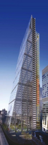
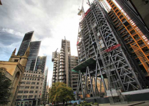
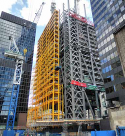
Leadenhall, aka the Cheesegrater, is going up fast in the City of London at a rate of approximately seven storeys per month. At 225m, the Rogers Stirk Harbour + Partners office tower will not break any height records. But it is remarkable for the unprecedented scale of its use of a “tube” structural perimeter envelope with an external support core.
Designed by partner Graham Stirk, it is firmly rooted in the practice’s family of structures that goes back to the nearby Lloyd’s Building and includes Lloyd’s Register of Shipping and 88 Wood Street. After a two-year pause, the British Land development is now back on track with an estimated completion date of May 2014.
Leadenhall comprises a tapering, perimeter-braced diagrid structure containing the office floors alongside a northern support core, which houses all passenger and goods lifts, service risers, on-floor plant and WCs. Office floors are connected to the structural tube at every floor without the need for further perimeter columns.
The main structure is set out on a grid of 16m x 10.5m, creating clear and flexible spans that would be impossible with a conventional internal core – only six internal columns are required on the largest floors. The contrasting colours of the expressed steelwork show the division between office and service space.
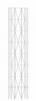
The expressed triangulated mega-frame is divided into eight of what the design team terms mega-levels of 28m high, each containing seven floors, apart from the first, which is five floors.
According to project architect Andy Young, the development of the external mega-frame allowed the creation of a non-standard plan, which creates a generous public space at the base.
Each floor diminishes in depth by 750mm as it rises, in response to the sight lines from Fleet Street to St Paul’s Cathedral, and this creates the distinctive cheesegrater shape.
Because of the large distances between the stiff node levels, the mega-frame structure requires a secondary stability system. This defines the main vertical emphasis of the building and consists of chevron-shaped, “K-bracing” located on the north-east and north-west corners. The bracing transfers lateral loads from all intermediate floor plates between the nodes back to the main frame at seven-storey intervals.
Behind this bracing are service riser and escape staircases. The tower is topped with a four storey “attic” containing generators, boilers and cooling towers.
“We wanted to express the structural external framework in a very strong way,” says Young. “The challenge has been dealing with the big loads within such a slender structure.”
- Diagrid on the elevations
The architect worked very closely with engineer Arup and steelwork contractor Watson Steel Structures (now Severfield (UK) Ltd) to design and deliver the optimal solution. With very few wet trades on site, construction is very much an assembly process, with an on-site team of only 150-200 compared to the 500-600 normally required for a building of this scale.
For fire protection, the whole structure is sprayed prior to site assembly with a marine standard, epoxy intumescent coating in layers of 3-12mm, depending on the thickness of the steel. This gives 90 minutes of fire protection. When complete, the structure will contain 500 tonnes of paint.
The building will be BREEAM “Excellent”, and includes a triple-glazed ventilated facade in the office areas. Here, there is a 1m wide cavity between the outer and inner glazing, which incorporates the structural frame. Computer-controlled blinds in the cavity automatically adjust in response to solar gain and glare to prevent the glass heating up. The resulting warmed air is discharged through vents at node level.
Floor-to-ceiling heights of 2.75m will be achieved within each 4m-high office storey, which contains a 150mm-deep concrete slab laid over 700mm steel beams and a raised floor of 150mm.
The 16,000-tonne steel superstructure is expected to complete by February. For Watson Steel Structures (now Severfield (UK) Ltd), the challenge has been meeting the requirements for both precision and aesthetic appearance for such complex connections and large-scale components – some weighing up to 40 tonnes – as well as ensuring that these could be assembled on site to the swift programme.
“It’s been a very close collaboration between Laing O’Rourke, Arup, Rogers Stirk Harbour + Partners and ourselves, working very much as a joined-up team,” says Peter Emerson, managing director of Watson Steel Structures (now Severfield (UK) Ltd).
Leadenhall will provide 56,000m2 of office space over 42 floors.
North core
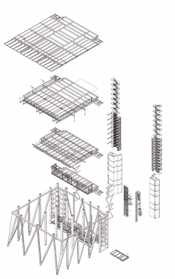
For speed and ease of construction, the components of the north core were largely prefabricated in “tables”, three per level and each consisting of a floor level with columns attached.
These were made by Watson Steel Structures (now Severfield (UK) Ltd), and then moved to another factory where they were fitted with primary M&E components and pre-cast concrete floors before being brought to site. Structures for the passenger and goods lifts are hung off the tables on either side.
The self–supporting core connects back to the mainframe on every level and is painted a distinctive yellow.
The Galleria
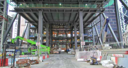
The first 28m-high megalevel, covering floors 0-5, is already taking shape. Known as The Galleria, it is conceived as an open, public area linking into the nearby St Helen’s Square.
“It is the only building of its type to have a big urban gesture,” says project architect Andy Young, adding that this ground-level amenity is a contrast to most tall buildings where the gestures are more about the skyline than the streetscape.
The diagrid terminates at ground nodes, which transfer loads into the four-storey basement. Designing the frame with the open structure at these lower levels was particularly challenging since this area lacks the lateral support of the floor plates. To compensate, the section size of the steel is increased, all sections are twin-webbed and the webs taper outwards in the middle of the section and then back to accommodate the bolt box connections. An additional central plate parallel to the webs projects through the flanges.
Prefabricated nodes
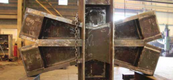
A family of 12 node types was designed to avoid site welding and instead facilitate easy Meccano-style assembly by using far fewer, but far bigger, “mega-bolts”. These join, typically, six mega-frame elements. In this way, the highly complex node construction and welding – involving up to 87 components and taking two people four weeks to complete – can be carried out at Watson Steel Structures’ (now Severfield (UK) Ltd) fabrication workshop before being taken to site and bolted to the columns and diagonals of the main structure in a relatively simple process.
“We’re making the fabrication job on site as easy as possible,” says Peter Emerson of Watson Steel Structures (now Severfield (UK) Ltd).
Nodes are typically 6m x 3m and weigh up to 30 tonnes. Connections transfer forces of up to 6,000 tonnes in at least three different directions simultaneously. Bolts are high-strength, threaded pre-tensioned bars up to 76mm in diameter. Connections can be made within the profile of the members and transfer their pre-stress to the ends of the members and nodes via stiffened plate bolt boxes between the flanges of the mega-frame sections.
| Architect | Rogers Stirk Harbour + Partners |
| Structural Engineer | Arup |
| Steelwork Contractor | Watson Steel Structures (now Severfield (UK) Ltd) |
| Main Contractor | Laing O’Rourke |
| Client | British Land |


