Difference between revisions of "Southmead hospital, Bristol"
| Line 31: | Line 31: | ||
An [[Facades_and_interfaces#Steel in atria and canopies|atrium]] running the full length of the building forms a natural separation between the ward and clinical blocks. This has a [[Facades_and_interfaces#Steel and glass facades|glazed roof]] which is supported by a series of prestressed single post [[Trusses|trusses]] using a bottom string of Macalloy bars. The [[Facades_and_interfaces#Steel in atria and canopies|atrium]] roof has three pyramid features (wind catchers) flanked by sloping wings, along its length. These roof structures incorporate movement joints and also make provision for differential building movement across the [[Facades_and_interfaces#Steel in atria and canopies|atrium]]. | An [[Facades_and_interfaces#Steel in atria and canopies|atrium]] running the full length of the building forms a natural separation between the ward and clinical blocks. This has a [[Facades_and_interfaces#Steel and glass facades|glazed roof]] which is supported by a series of prestressed single post [[Trusses|trusses]] using a bottom string of Macalloy bars. The [[Facades_and_interfaces#Steel in atria and canopies|atrium]] roof has three pyramid features (wind catchers) flanked by sloping wings, along its length. These roof structures incorporate movement joints and also make provision for differential building movement across the [[Facades_and_interfaces#Steel in atria and canopies|atrium]]. | ||
| − | <gallery widths=250px heights=335px | + | <gallery widths=250px heights=335px style="float:right;" wrap=true> |
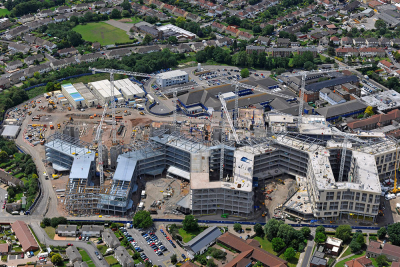
Image:Southmead-1.jpg|Steel has been [[Construction#Steel erection|erected]] by a combination of [[Construction#Mobile cranes|mobile crane]] and cherry picker | Image:Southmead-1.jpg|Steel has been [[Construction#Steel erection|erected]] by a combination of [[Construction#Mobile cranes|mobile crane]] and cherry picker | ||
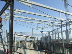
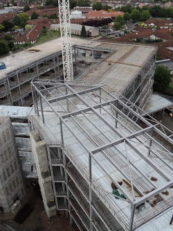
Image:Southmead-2.jpg|All blocks will have a covered rooftop plant area | Image:Southmead-2.jpg|All blocks will have a covered rooftop plant area | ||
Revision as of 12:13, 12 March 2019
Article in NSC February 2012
Framing hospital excellence
A new 800 bed acute hospital is rapidly taking shape in north Bristol, a project which is making use of more than 6,000t of structural steelwork and aiming to achieve a BREEAM ‘Excellent’ rating.
Bristol’s new Southmead Hospital is being constructed in two phases with most works being completed in phase 1. The main hospital which includes the clinical and ward blocks is programmed to complete at the end of March 2014 after which the new hospital will open. The second phase picks up the remaining elements including external works and landscape and will be complete towards the end of 2015.
During the construction programme the existing hospital remains open, although some buildings have had to be demolished to make space for the new build. Prior to phase two of the works beginning, all of the old hospital buildings will be demolished.
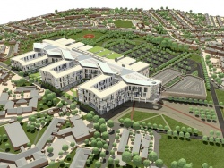
Structurally the new main building is split in two, with a concrete framed clinical block containing operating theatres, medical rooms and the emergency department separated from a steel framed ward block by a large steel framed and glazed atrium/concourse.
Both the clinical and ward block are subdivided into thirds, with two movement joints positioned along the structure’s length. For the steel framed ward building the movement joints connect to the structure’s three concrete cores. Due to space constraints, the usual double column movement joint configuration could not be employed and steelwork contractor Severfield-Reeve Structures (now Severfield plc) has installed a single beam with a sliding joint.
The ward block’s frame is a beam and column structure supporting profiled metal decking with concrete infilled floors designed compositely with the floor beams. Loads are transferred vertically down the columns which are supported on pad foundations or piles.
Building a hospital with two framing materials has offered advantages to the project team, according to Jack Mitchell, TPS Associate Director. “Both blocks are going up simultaneously and this will mean an earlier fit-out. Also, by having two production streams, we weren’t putting all of our eggs into one basket from a design perspective which in turn has helped maintain the construction programme.”
Vertical movement joints consequently divide the ward building into three sectors (1,2 and 3), each consisting of two wings which form an enclosed courtyard within a horseshoe shape. Each sector steps down in height, with sector 1 comprising of seven levels, sector 2 having six levels and sector 3 stepping down to four levels.
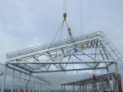
Trusses will support the central atrium's glazed roof
“The grid pattern layout for the wards has been adapted to suit the clinical needs of the hospital,” explains Mr Mitchell. “The structural design was developed to accommodate these needs.” The width of the ward block has been divided into 8.35m and 5.75m bays to suit corridor positions. Longitudinally maximum bays of 9.3m are used, while secondary beams at 3.1m centres divide the long bays to limit the decking span.
Stability for the steelwork derives from three concrete cores and by the diaphragm actions of the composite floor deck transferring forces back to a combination of steel braced bays and portalised sections of the structure.
Vertical circulation is provided via lifts and stairs located in the three central cores within the atrium. The steel stairs cantilever out from the cores and were fabricated by Atlas Ward Structures (now Severfield (Design & Build) Ltd.). They arrived on site fully assembled in flights, which aided a quick erection process.
An atrium running the full length of the building forms a natural separation between the ward and clinical blocks. This has a glazed roof which is supported by a series of prestressed single post trusses using a bottom string of Macalloy bars. The atrium roof has three pyramid features (wind catchers) flanked by sloping wings, along its length. These roof structures incorporate movement joints and also make provision for differential building movement across the atrium.
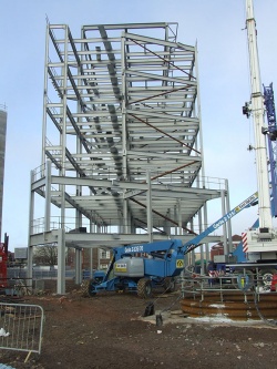
Steel has been erected by a combination of mobile crane and cherry picker
Erecting the feature atrium roof pyramids presented the Severfield erectors (SteelCraft, now Severfield (UK) Ltd) with their trickiest work, says Steve Harrington, Severfield-Reeve Structures (now Severfield (UK) Ltd ) Site Manager. Each feature, measuring 23m long × 9m high × 18m wide, was fully assembled on the ground before being lifted into place. Basically, the pyramids are trusses which will support the atrium’s glazing, however each one took a week to assemble and one hour to lift into position. “The pyramids are formed from horizontal box sections and vertical tubes,” says Mr Harrington. “Assembly was difficult as there is little room on the ground for storage, and so all the steel members had to arrive in a correct sequence.”
Sequencing has also played a significant role in the overall steelwork erection programme. Severfield programmed and controlled deliveries to ensure steelwork arrived in a just-in-time basis, which has allowed most of the steelwork to be erected immediately it gets to site.
| Architect | BDP |
| Structural Engineer | TPS |
| Steelwork Contractor | Severfield-Reeve Structures (now Severfield plc) |
| Main Contractor | Carillion |
| Client | Bristol NHS Trust |
Safe practice saves time
When it came to the initial sections of steelwork to be erected, those which connect to the cores, steelwork contractor Severfield-Reeve Structures used a new time saving method.
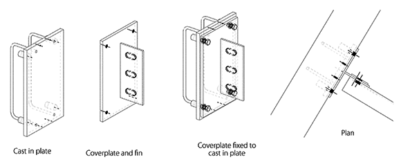
“The cast-in plates in the concrete cores already had cleats with pre-drilled holes in place,” says Steve Harrington, Severfield Site Manager. “With taps in-place and already surveyed the connecting beams were quicker to install, which saved a lot of time.”
This new methodology meant that a fin plate was welded to the connecting beam on the ground and prior to the member being lifted into place. Importantly, the procedure negated the need to weld aloft from a cherrypicker eliminating the risks and hazards associated with working at height.
Severfield used a similar method for the cores internal steelwork, which form landings for all floor levels. Internal cast-in plates were put in place during the core’s construction and then surveyed. The survey results were then returned to the drawing office where fabrication drawings were prepared in accordance with the received information, which allowed bespoke steelwork to be fabricated.
Each level’s steelwork was assembled on the ground and lowered into the core fully complete. Once in position retractable connections were extended to bolt directly to the core’s embedded plates. Once a level was decked, this procedure was then repeated for each floor level, using the completed steelwork below as a working platform.


