Difference between revisions of "Highpoint crown steelwork, London"
(Created page with "==Article in [http://www.newsteelconstruction.com/wp/wp-content/uploads/digi/NSCSep17digi/index#/22/ NSC September 2017]== {{#image_template:image=File:Highpoint_crown-1.jpg...") |
|||
| (4 intermediate revisions by the same user not shown) | |||
| Line 1: | Line 1: | ||
| − | ==Article in [ | + | ==Article in [https://www.newsteelconstruction.com/wp/wp-content/uploads/digi/2017pdf/NSCSep17digi.pdf#page=22 NSC September 2017]== |
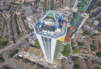
{{#image_template:image=File:Highpoint_crown-1.jpg|align=right|wrap=true|caption=The steel crown tops one of south London’s tallest towers|width=400}} | {{#image_template:image=File:Highpoint_crown-1.jpg|align=right|wrap=true|caption=The steel crown tops one of south London’s tallest towers|width=400}} | ||
'''Crowning glory'''<br> | '''Crowning glory'''<br> | ||
| Line 12: | Line 12: | ||
All of the [[Residential_and_mixed-use_buildings#Balcony systems|balconies]], which are positioned in each of the building’s four corners, are connected to each other via Macalloy bars, and tethered to the crown to create a unified structural system. Structural engineer AKT II designed a series of bespoke connections for each balcony that limit movement under [[Design_codes_and_standards#Thermal actions|thermal load cases]], but provide restraint under dynamic conditions. | All of the [[Residential_and_mixed-use_buildings#Balcony systems|balconies]], which are positioned in each of the building’s four corners, are connected to each other via Macalloy bars, and tethered to the crown to create a unified structural system. Structural engineer AKT II designed a series of bespoke connections for each balcony that limit movement under [[Design_codes_and_standards#Thermal actions|thermal load cases]], but provide restraint under dynamic conditions. | ||
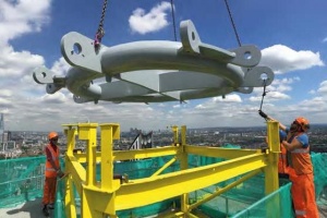
| + | {{#image_template:image=File:Highpoint_crown-2.jpg|align=left|wrap=true|caption=The tubular inner ring is installed|width=300}} | ||
| + | The crown itself is positioned at a height of 154m, and this threw up a number of challenges, one of which was [[Health_and_safety|working safety]] at such a height. All pieces of equipment and tools had to be tethered at all times, as dropping anything from the tower would have been highly dangerous. | ||
| − | |||
| − | |||
The crown only has 24 main structural steel components, not a large total by any stretch of the imagination. However, it was essential that once each component was lifted up onto the roof, they all fitted perfectly. “The buildability of the crown was important, especially at such a height. We decided the best way to ensure the [[Construction#Steel erection|erection]] sequence went to plan was to undertake a [[Accuracy_of_steel_fabrication#Trial erection|trial erection]] before bringing all of the components to site,” says Mace Associate Director Bart Lemmens. “Mace did a similar [[Accuracy_of_steel_fabrication#Trial erection|trial erection]] procedure with the top sections of the [[The_Shard,_London|Shard]], known as the Spire, so we’ve used our company’s experience on this project.” | The crown only has 24 main structural steel components, not a large total by any stretch of the imagination. However, it was essential that once each component was lifted up onto the roof, they all fitted perfectly. “The buildability of the crown was important, especially at such a height. We decided the best way to ensure the [[Construction#Steel erection|erection]] sequence went to plan was to undertake a [[Accuracy_of_steel_fabrication#Trial erection|trial erection]] before bringing all of the components to site,” says Mace Associate Director Bart Lemmens. “Mace did a similar [[Accuracy_of_steel_fabrication#Trial erection|trial erection]] procedure with the top sections of the [[The_Shard,_London|Shard]], known as the Spire, so we’ve used our company’s experience on this project.” | ||
Bourne Steel’s [[Accuracy_of_steel_fabrication#Trial erection|trial erection]], undertaken at its [[Fabrication|fabrication]] yard, was done in such a way as to replicate the actual [[Construction#Steel erection|erection]] even though it was performed at ground level. This went as far as marking out a space around the crown, identical in size to the top of the tower, in which all the work was done. “We ironed out a number of issues, not just ensuring that all the components fitted and checking [[Construction#Tolerances|tolerances]], we also worked out the best position for our MEWPs, bearing in mind that space was very tight on top of the tower,” says Bourne Steel Project Manager Stephane Dubois. “To ensure the actual [[Construction#Steel erection|erection]] sequence was also successful, and that all the pieces fitted together the components, such as the four arms that consist of two spliced sections, were kept as pairs even though they are all identical. This was maintained from [[Fabrication|fabrication]], through the [[Accuracy_of_steel_fabrication#Trial erection|trial assembly]] and to the main [[Construction#Steel erection|erection]] sequence. This procedure guaranteed that all the pieces fitted perfectly a second time.” | Bourne Steel’s [[Accuracy_of_steel_fabrication#Trial erection|trial erection]], undertaken at its [[Fabrication|fabrication]] yard, was done in such a way as to replicate the actual [[Construction#Steel erection|erection]] even though it was performed at ground level. This went as far as marking out a space around the crown, identical in size to the top of the tower, in which all the work was done. “We ironed out a number of issues, not just ensuring that all the components fitted and checking [[Construction#Tolerances|tolerances]], we also worked out the best position for our MEWPs, bearing in mind that space was very tight on top of the tower,” says Bourne Steel Project Manager Stephane Dubois. “To ensure the actual [[Construction#Steel erection|erection]] sequence was also successful, and that all the pieces fitted together the components, such as the four arms that consist of two spliced sections, were kept as pairs even though they are all identical. This was maintained from [[Fabrication|fabrication]], through the [[Accuracy_of_steel_fabrication#Trial erection|trial assembly]] and to the main [[Construction#Steel erection|erection]] sequence. This procedure guaranteed that all the pieces fitted perfectly a second time.” | ||
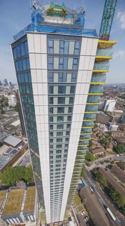
| − | {{#image_template:image=File:Highpoint_crown-3.jpg|align=right|wrap=true|caption=Working at height was one of the main challenges which had to be overcome|width= | + | {{#image_template:image=File:Highpoint_crown-3.jpg|align=right|wrap=true|caption=Working at height was one of the main challenges which had to be overcome|width=250}} |
The [[Accuracy_of_steel_fabrication#Trial erection|trial erection]] also included assembling a bespoke temporary trestle, which was designed to cater for jacking members into position, as well as dealing with uplift of members while they were in a temporary condition. The trestle also has access platforms to provide erectors with safe and convenient working areas during the installation programme. Once the [[Accuracy_of_steel_fabrication#Trial erection|trial assembly]] was complete, the trestle was separated into two parts to allow it to be [[Fabrication#Handling and transportation|transported to site]]. Once at the project, the 3.5t trestle was re-assembled before being lifted into place by the on-site [[Construction#Tower cranes|tower crane]]. | The [[Accuracy_of_steel_fabrication#Trial erection|trial erection]] also included assembling a bespoke temporary trestle, which was designed to cater for jacking members into position, as well as dealing with uplift of members while they were in a temporary condition. The trestle also has access platforms to provide erectors with safe and convenient working areas during the installation programme. Once the [[Accuracy_of_steel_fabrication#Trial erection|trial assembly]] was complete, the trestle was separated into two parts to allow it to be [[Fabrication#Handling and transportation|transported to site]]. Once at the project, the 3.5t trestle was re-assembled before being lifted into place by the on-site [[Construction#Tower cranes|tower crane]]. | ||
| Line 26: | Line 26: | ||
Connecting each of the four arms is a large tubular central inner ring [[Fabrication|fabricated]] from 25mm-thick [[Steel_construction_products#Flat products - plates|plate]]. This was the first of the crown’s components to be installed. Once it was in place on top of the temporary trestle, each of the four 8m-long tapering inner arms were installed between the ring and the saddle. With each weighing 7.5t, these were the heaviest steel elements to be installed, but they were within the [[Construction#Tower cranes|tower crane’s]] 9t lifting capacity. “As each and every individual steel component was installed, everything had to be continuously surveyed for uplift, sag and the correct geometry, with the trestle’s jacks then adjusted accordingly,” says Mr Lemmens. | Connecting each of the four arms is a large tubular central inner ring [[Fabrication|fabricated]] from 25mm-thick [[Steel_construction_products#Flat products - plates|plate]]. This was the first of the crown’s components to be installed. Once it was in place on top of the temporary trestle, each of the four 8m-long tapering inner arms were installed between the ring and the saddle. With each weighing 7.5t, these were the heaviest steel elements to be installed, but they were within the [[Construction#Tower cranes|tower crane’s]] 9t lifting capacity. “As each and every individual steel component was installed, everything had to be continuously surveyed for uplift, sag and the correct geometry, with the trestle’s jacks then adjusted accordingly,” says Mr Lemmens. | ||
| − | <gallery | + | <gallery widths=300px heights=200px> |
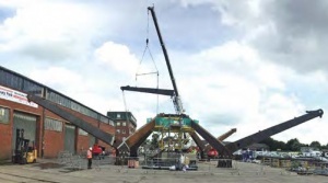
Image:Highpoint_crown-4.jpg| A [[Accuracy_of_steel_fabrication#Trial erection|trial erection]] of the crown was undertaken | Image:Highpoint_crown-4.jpg| A [[Accuracy_of_steel_fabrication#Trial erection|trial erection]] of the crown was undertaken | ||
Image:Highpoint_crown-5.jpg| Model showing the steelwork and the balcony-supporting Macalloy bars | Image:Highpoint_crown-5.jpg| Model showing the steelwork and the balcony-supporting Macalloy bars | ||
| Line 54: | Line 54: | ||
|} | |} | ||
| − | [[Category:Case studies | + | [[Category:Case studies - Residential and mixed-use buildings]] |
Latest revision as of 15:09, 9 February 2021
Article in NSC September 2017
Crowning glory
A trial erection helped overcome a number of logistical challenges involved in the construction of a structural steelwork crown that tops a London high-rise residential tower.
By Martin Cooper
Perched atop a 47-storey high-rise residential tower in south London, a steel structure with a difference has been completed following a complex and demanding design, trial assembly and erection programme.
Known as Highpoint, the tower, which is located on Newington Butts overlooking the Elephant & Castle roundabout, will at 150m high be one of the capital’s tallest residential buildings. Being delivered by main contractor Mace, it will accommodate a total of 457 apartments, split between 279 private rental sector flats as well as 115 affordable units and 64 shared ownership flats located on the lower floors.
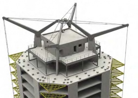
Giving the project a regal aspect, the uppermost level accommodates a four-pronged steel crown, which has been designed as an integrated architectural and structural system supporting the building’s balconies via a series of vertical Macalloy bars. Vibration could have been an issue for the steel balconies, as they cantilever by up to 4m. However, the crown will provide the necessary dampening effects to reduce the dynamic response of the balconies as the crown will remain stable even under extreme weather conditions.
All of the balconies, which are positioned in each of the building’s four corners, are connected to each other via Macalloy bars, and tethered to the crown to create a unified structural system. Structural engineer AKT II designed a series of bespoke connections for each balcony that limit movement under thermal load cases, but provide restraint under dynamic conditions.
The crown itself is positioned at a height of 154m, and this threw up a number of challenges, one of which was working safety at such a height. All pieces of equipment and tools had to be tethered at all times, as dropping anything from the tower would have been highly dangerous.
The crown only has 24 main structural steel components, not a large total by any stretch of the imagination. However, it was essential that once each component was lifted up onto the roof, they all fitted perfectly. “The buildability of the crown was important, especially at such a height. We decided the best way to ensure the erection sequence went to plan was to undertake a trial erection before bringing all of the components to site,” says Mace Associate Director Bart Lemmens. “Mace did a similar trial erection procedure with the top sections of the Shard, known as the Spire, so we’ve used our company’s experience on this project.”
Bourne Steel’s trial erection, undertaken at its fabrication yard, was done in such a way as to replicate the actual erection even though it was performed at ground level. This went as far as marking out a space around the crown, identical in size to the top of the tower, in which all the work was done. “We ironed out a number of issues, not just ensuring that all the components fitted and checking tolerances, we also worked out the best position for our MEWPs, bearing in mind that space was very tight on top of the tower,” says Bourne Steel Project Manager Stephane Dubois. “To ensure the actual erection sequence was also successful, and that all the pieces fitted together the components, such as the four arms that consist of two spliced sections, were kept as pairs even though they are all identical. This was maintained from fabrication, through the trial assembly and to the main erection sequence. This procedure guaranteed that all the pieces fitted perfectly a second time.”
The trial erection also included assembling a bespoke temporary trestle, which was designed to cater for jacking members into position, as well as dealing with uplift of members while they were in a temporary condition. The trestle also has access platforms to provide erectors with safe and convenient working areas during the installation programme. Once the trial assembly was complete, the trestle was separated into two parts to allow it to be transported to site. Once at the project, the 3.5t trestle was re-assembled before being lifted into place by the on-site tower crane.
Steelwork erection initially involved Bourne Steel installing a steel-framed enclosure at level 46 floor level that provided access to the crown. The roof of this floor will be used as a maintenance platform once the project is complete, while level 46 will accommodate a communal space offering panoramic views over London.
The crown has been designed as a symmetrical structure consisting of four V-shaped arms in elevation. These four arms are supported, via a saddle connection, on four diagonal concrete walls placed at each corner of the core. The V-shaped arms are formed by tapering steel box sections. The arms are connected to horizontal Macalloy bars which span between the long and short arms of the V, and vertical Macalloy bars which support the balconies below.
Connecting each of the four arms is a large tubular central inner ring fabricated from 25mm-thick plate. This was the first of the crown’s components to be installed. Once it was in place on top of the temporary trestle, each of the four 8m-long tapering inner arms were installed between the ring and the saddle. With each weighing 7.5t, these were the heaviest steel elements to be installed, but they were within the tower crane’s 9t lifting capacity. “As each and every individual steel component was installed, everything had to be continuously surveyed for uplift, sag and the correct geometry, with the trestle’s jacks then adjusted accordingly,” says Mr Lemmens.
A trial erection of the crown was undertaken
Having installed the four inner arm sections, the saddle connection was then grouted onto the fin wall in its fixed and final position. This provided the portion of the crown already erected with stability, although the continual monitoring still had to be continued.
The tapered 11m-long outer arms were then fixed to the saddle via hidden bolted connections. The protruding ends of each outer arm were then connected back to the inner ring via a pair of 85mm diameter Macalloy bars. “This size of bar is ordinarily seen on bridges but, because of the potential dynamic affects due to winds at high elevations, a large bar was needed to provide the required mass damping and stiffness to mitigate this,” says AKT II Associate Director Tony Macey.
“Connecting and tensioning up all of the Macalloys was a tricky balancing act as each one introduced movement to the crown, which had to be carefully controlled,” continues Mr Lemmens. Having fully assembled the steel crown and made sure all of the bars were tensioned, the final task Bourne Steel had to perform was to dismantle the trestle. This was done piece by piece using the tower crane.
The Highpoint project is scheduled for completion in 2018.
| Design Architect | Rogers Stirk Harbour + Partners |
| Delivery Architect | Axis |
| Structural Engineer | AKT II |
| Steelwork Contractor | Bourne Steel |
| Main Contractor | Mace |
| Main Client | Newington Butts Developments |


