


Multi-girder composite bridges
Multi-girder bridges are one of the most common types of medium span composite bridge in the UK. Multi-girder construction is used for single spans and for continuous multiple spans, and it is particularly effective where construction depth is limited. This article provides a description of the features of this type of bridge and introduces some of the structural design considerations.
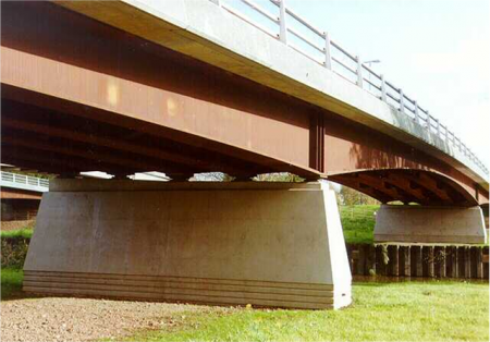

Westgate bridge, Gloucester
[top]Configuration of a multi-girder bridge
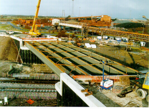
In multi-girder construction, a number of similarly sized longitudinal plate girders are arranged at uniform spacing across the width of the bridge, as shown in the typical cross section below. The deck slab spans transversely between the longitudinal girders and cantilevers transversely outside the outer girders. The girders are braced together at supports and at some intermediate positions. Composite action between the reinforced concrete deck slab and the longitudinal girders is achieved by means of shear connectors welded on the top flanges of the steel girders.
The arrangement shown in the image below is common where permanent formwork is used and shows four girders of equal depth and with a slab surface that follows the camber of the road. A footway/verge is provided either side of a 2-lane single carriageway and parapets/restraint barriers are mounted on the edge beams.


[top]Longitudinal girders
The steel girders are usually fabricated I-section plate girders; for smaller spans, it is possible to use rolled section beams (Universal Beams) but, for reasons discussed below, rolled sections are rarely used today. Usually, girders are spaced between about 3.0 and 4.0m apart, and thus, for an ordinary two-lane overbridge, four girders are provided. This suits the deck slab, which has to distribute the vertical loads from the wheels.
[top]Plate girders
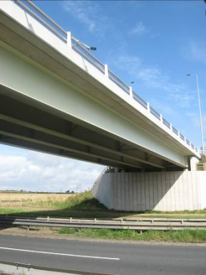

A66 Overbridge, Longnewton
The use of plate girders gives scope to vary the girder sections to suit the loads carried at different positions along the bridge. The designer is free to choose the thickness of web and size of flange to suit the internal forces at different positions along the length of the span, though it must be remembered that too many changes may not lead to economy, because of the additional fabrication work. Splices are expensive, whether bolted or welded.
Most often, the girders have parallel flanges, that is, they have a constant depth. However, with plate girders, the designer can also choose to vary the depth of the girder along its length. For longer spans it is quite common to increase the girder depth over intermediate supports. For spans below about 50m, the choice (constant or varying depth) is often governed by aesthetics. Above 50m, varied depth may offer economy because of the weight savings possible in midspan regions. The variation in depth can be achieved either by straight haunching (tapered girders) or by curving the bottom flange. The shaped web, either for a variable depth or constant depth girder with a vertical camber, is easily achieved by profile cutting during fabrication. Generally, webs have a high depth/thickness ratio and this leads to the need for intermediate transverse web stiffeners in regions of high shear (near supports).
Very occasionally, for reasons of appearance, the outermost girders are designed as a J-section; the bottom flange projects only on the inner side of the web. Requests for this detail arise from a dislike of the flange outstand, although there is little visible difference and the distinction is not noticed by most people. Use of such a section introduces torsional effects (because the shear centre is outside the line of the web) that require very careful consideration during design and construction, with significant penalty on costs an increased hazards during construction.
Also, on occasion, relatively small box girders are used in multi-girder construction. Box girders require special design consideration, because of their high torsional stiffness and high cost of fabrication. Advice on construction costs may be obtained from steelwork contractors.
[top]Rolled section girders
Universal beams up to 1016 mm deep are available in the section range covered by BS EN 10365[1]. Such beams would provide sufficient bending resistance for single spans up to about 25m and for continuous spans up to about 30m, although the webs may be rather thin for the high shears associated with longer spans, unless the bridge is lightly loaded – a farm access bridge or a footbridge, for example.
Very little fabrication is necessary with universal beams, usually only the fitting of stiffeners over support bearings and the attachment of bracing. However, the beams often need to be curved in elevation to suit either the road profile or the pre-cambering for dead load; this can be carried out by specialist companies using heavy rolling equipment but it does add to cost. Even for smaller spans, universal beams can often be more economically replaced by similar size plate girders. Steelwork contractors can advise on the relative economy.
[top]Bracing
[top]Support bracing
Girders need to be braced together at support positions, for stability and to effect the transfer of horizontal loads (wind and skidding forces) to the bearings that provide transverse restraint (usually one at each support position).
Restraints at supports are provided either by triangulated bracing systems or by horizontal beams, usually channel sections. The bracing systems at the end supports of non-integral bridges are usually also required to support the end of the deck slab. Integral bridges will require bracing at the end supports for the construction condition.
A typical bracing arrangement at an intermediate support is shown below:


[top]Intermediate bracing
In the completed bridge, intermediate bracing is usually needed at discrete positions in the spans of multi-span bridges, to stabilise the bottom flanges adjacent to intermediate supports (where they are in compression). During construction, bracing is needed to stabilise both the bottom flanges adjacent to intermediate supports and the top flanges in midspan regions. Where the girders are curved in plan, bracing will also be needed to provide ‘radial’ restraint to the bottom flanges.
In most cases, the most effective bracing system is a triangulated frame between adjacent girders. In the completed bridge this provides a very stiff restraint path from the plane of the deck slab through to the bottom flanges. In the construction condition, intermediate bracing between girders, without plan bracing, provides ‘torsional restraint’ – see discussion of the effectiveness of such bracing in Section 7 of SCI P356. As an alternative, ‘channel bracing’ is often used with shallow main girders; the stiff channel has rigid connections to the main girders.
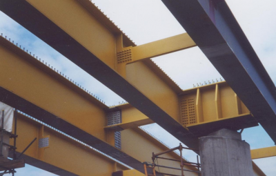
Intermediate bracing that is continuous across more than two main girders will participate in the global action and will distribute loading in any one lane to several main girders. However, such continuity does not provide much benefit to the design of the main girders(because the design case is usually with all lanes loaded) and introduces stress reversals in the bracing and its connections; the connection details are potentially prone to fatigue. To avoid this fatigue situation, designers use non-continuous bracing, where main girders are connected in pairs, with no bracing between one pair and the next, as shown below.


Intermediate bracing may also be required if the headroom below the bridge is such that collision loading on the bridge soffit needs to be considered. Bracing at intervals provides restraint to the bottom flange and a load path to the bridge deck. In such cases, the bracing at supports has to be designed to transfer the collision loading down to the restrained bearings.
Although continuity of transverse bracing is not needed (and not desirable, for the reason given above), tie/strut members are sometimes provided between the pairs of beams during construction in order either to share wind loads or to control the spacing between the pairs. Such members may need to be removed once the slab has been cast, because of their unwanted structural participation under traffic loading. Removal is a potentially hazardous activity that needs to be considered carefully when planning the construction method. Any construction bracing that is left in place should be assessed for fatigue.
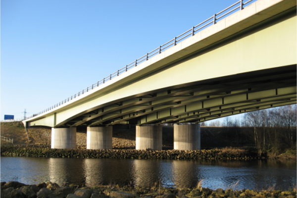

Lagentium Viaduct, A1(M) Darrington to Dishforth
[top]Plan bracing
Plan bracing to the top flange is an alternative way to provide a stiff lateral restraint to the top flanges at the bare steel stage. Although such bracing is very effective in restraining the compression flange in midspan, its presence complicates construction. The two possible locations of plan bracing are above the top flange (connected to cleats on the top flange) and below the top flange, bracing above the top flange (shown below) adds difficulty to the placing of reinforcement and conflicts with the use of permanent formwork; it is rarely used now.
Bracing below the top flange, shown below, avoids the clash with reinforcement but needs to avoid any temporary formwork. The bracing would need to be removed after casting (because it would attract unwanted forces when the slab is subject to local loading above it) and is thus not favoured by constructors.
Plan bracing to top flanges
Humber Road Bridge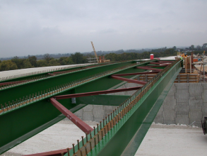
Plan bracing below top flange
A41 Aston Clinton Bypass


Plan bracing is occasionally provided to the bottom flanges of narrow bridges when the spans are long (over about 60m) in order to improve the overall torsional stiffness of the bridge (at the completed stage) and thus reduce susceptibility to aerodynamic instability. Such improvement in torsional stiffness would also be beneficial for a bridge with significant curvature in plan. The presence of the bracing effectively creates a pseudo-box.
[top]Crosshead girders

(Image courtesy of Mabey Bridge Ltd.)
At intermediate supports, it is sometimes desirable to reduce the number of columns and bearings. Typically, instead of a bearing directly under each girder, one bearing is provided midway between each pair of girders, with a crosshead girder to transfer the reactions. Such an arrangement is particularly common with large skew. An example of a crosshead is shown below. (This illustration also shows a continuity girder between the central girder; such a girder is advantageous for construction, to minimise twist during concreting, but is not normally needed for the permanent condition).
[top]Case studies


[top]References
- ↑ BS EN 10365:2017 Hot rolled steel channels, I and H sections. Dimensions and masses. BSI
[top]Resources
- Hendy, C.R.; Cooper, M.C. (2025) Steel Bridge Group: Guidance Notes on best practice in steel bridge construction (7th Issue). (P185). SCI
- Iles, D.C. (2010) Composite highway bridge design. (P356 including corrigendum, 2014). SCI
- Iles, D.C. (2010) Composite highway bridge design: Worked examples. (P357 including corrigendum, 2014). SCI
- Iles, D.C. (2012) Design of composite highway bridges curved in plan. (P393). SCI
- Iles, D.C. (2012) Determining the buckling resistance of steel and composite bridge structures. (ED008). SCI
- Iles, D.C. (2015) Determining design displacements for bridge movement bearings. (P406). SCI
- Steel Bridges: A practical approach to design for efficient fabrication and construction, 2010, (Publication no. 51/10), BCSA,
- Guide to the Erection of Steel Bridges, 2005, (Publication no. 38/05), BCSA
- Carbon footprint tool for steel composite highway bridges
- Preliminary steel bridge design charts:
- Chart finder
- Spreadsheet tool
- User manual
- All three of which can be found on the BCSA web site
[top]See also
- Ladder deck composite bridges
- Integral bridges
- Box girder bridges
- Bridges - initial design
- Modelling and analysis of beam bridges
- Design of beams in composite bridges
- Shear connection in composite bridge beams
- Fatigue design of bridges
- Bracing systems
- Stiffeners
- Connections in bridges
- Bridge articulation and bearing specification
- Plan curvature in bridges
- Skew bridges
- Design for steel bridge construction