Tower Wharf, Birkenhead
Article in NSC September 2015
Steel spearheads docks regeneration
An £11M flagship steel-framed office development - one of the initial phases of Birkenhead’s Wirral Waters regeneration scheme – will be completed shortly.
Wirral Waters is said to be the largest regeneration project in the UK and will eventually transform more than 500 acres of Birkenhead’s former docks into a new business and leisure destination.
Developer Longmeadow Estates says it is also set to become one of the most sustainable enterprise zones in the country as well as an exciting place to live, work and spend time. Design plans envisage an area that is not over reliant on the car and to achieve this aim the construction of a tram network to link into the existing Merseyrail system has been mooted.
At its heart, the project seeks to use the unique water assets of the city to drive growth across all sectors; for trade, for jobs, for energy, for transport and for leisure. Creating new employment is one of the key drivers and Wirral Waters could create as many as 20,000 jobs in the coming years, by encouraging firms to relocate to its new and modern premises.
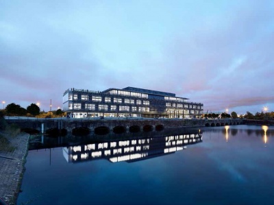
One of the scheme’s first office developments is known as Tower Wharf. It is a four-storey building aiming for a BREEAM ‘Excellent’ rating and will offer 4,450m2 of flexible Grade A open plan office space. The building includes a top floor roof terrace affording views over the adjacent former dockside waterfront and the extensive landscaping that will eventually surround the structure.
“This project will deliver much needed accommodation and employment opportunities for a scheme which will boost business and generate investment into the area,” explains Eric Wright Construction Operations Director Jonathon Rayner.
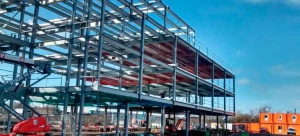
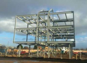
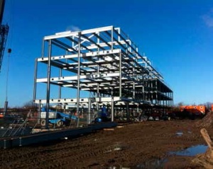
Working on behalf of the main contractor Eric Wright Construction, Leach Structural Steelwork has fabricated, supplied and erected 375t of steel for Tower Wharf. Using one 35t-capacity mobile crane for the entire steel erection programme, Leach also installed 6,000m2 of metal decking and two precast staircases during its eight–week onsite programme.
“A steel construction solution was chosen for this building as it was the most economical,” explains Muir Associates Director Mark Jones.
The steel frame is founded on piled foundations and has been designed and erected around an irregular grid pattern to suit the architect’s layout. However, the majority of the grid is based around columns set at 7.5m centres, which suits the curtain walling mullions across the building.
The structure is approximately 98m long × 16.5m wide and internally it has a predominantly open plan design, while externally it will be fully clad with glass.
According to project architect Falconer Chester Hall, the structure references the materials and proportions of the surrounding buildings, with its recessed ground floor and the stepped back roof profile creating a shape reminiscent of the trade vessels that once would have stood in the nearby docks.
Structural stability is achieved by the use of moment frames, and bracing located in lift and stair cores. Additional stability is derived from feature architectural Macalloy cross bracing that has been installed at both end elevations. This will remain visible within the completed scheme, while internally further Macalloy bracing, around staircases, will also be left exposed.
Summing up, Cllr Phil Davies, Leader, Wirral Council, said: “This is of huge importance, given that it kick starts the regeneration of Wirral Waters. It is a significant step in our vision to regenerate Wirral, and demonstrates that even at a time of such economic difficulties we continue to make significant progress towards the delivery of our ambitious investment strategy. The challenge for us now is to ensure this exciting vision delivers real benefits for residents and businesses of Wirral and the Liverpool City region.”
Bracing provides most of the structural stability
Round Bar Cross Bracing
By Dr Richard Henderson (SCI)
Tower Wharf has a narrow rectangular footprint with the long edges stepped out at first floor level on both sides of the building. The cantilevers at the ends of the transverse frames mean that moment frames are a logical choice to provide lateral stability in the building in the transverse direction and each frame contributes. However, at the ends of the building, the first floor steps out in both directions and the columns above first floor in the end frames do not extend to the ground. There is therefore no opportunity to use a moment frame for transverse stability in these locations.
Diagonal bracing is the logical alternative and is placed in the end elevation above first floor level. The horizontal shear is transferred through the first floor diaphragm to the line of the inset columns from ground to first floor and then to the ground through bracing in this vertical plane. The full height glazing in the end elevations allows clear views into the building and displays the cross bracing clearly. A simple and complete solution is provided by the Macalloy system which includes rods, clevis-type terminal connectors, turnbuckles for tensioning and a connecting ring for the central node. Stainless steel material was initially proposed but painted carbon steel was adopted instead for economic reasons.
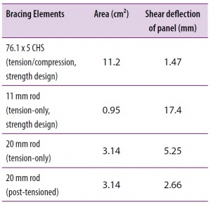
Macalloy bars have high tensile strength, so a bar of small cross-section will carry the bracing loads. This means that a bracing panel potentially has relatively low shear stiffness (compared for example with tension/ compression bracing which is designed for flexural buckling) because the stiffness depends on the area of cross-section of the bar. By tensioning the bracing, both diagonals contribute to the shear stiffness of the panel (which would clearly not be so if the compression diagonal went slack). The distributed lateral stability system in the building means that the lateral stiffness of the braced panel is similar to the stiffness of an individual moment frame. In a building where the lateral stability system was concentrated into a small number of braced bays, rod bracing would not be sufficiently stiff to provide an effective solution.
As an illustration, the shear deflection of a hypothetical 3.5 m square braced panel transferring 35 kN, consisting of 203UKC46 columns and a 305×127UKB37 beam with different bracing systems is compared in the table (right).
| Architect | Falconer Chester Hall |
| Structural Engineer | Muir Associates UK |
| Steelwork Contractor | Leach Structural |
| Main Contractor | Eric Wright Construction |
| Main Client | Longmeadow Estates |


