Difference between revisions of "Cabot Circus, Bristol"
(Created page with "==Structural Steel Design Awards 2009 - Winner== {{#image_template:image=File: R2 image.png|align=right |wrap=true|width=400}} Cabot Circus is ...") |
|||
| Line 15: | Line 15: | ||
The fabricated frames were [[Construction#Tower cranes|craned]] onto a full birdcage scaffold covering the entire 2,000m<sup>2</sup> of the [[Facades_and_interfaces#Steel in atria and canopies|atrium]]. On completion of the internal grid, the 355mm diameter circular edge frame, incorporating a 450mm wide walk-in gutter profile was positioned and securely supported on the scaffold. The perimeter members were also welded connecting the internal grid and the boundary elements. A number of surveys were carried out throughout the assembly of the roofs to ensure the roof nodes were kept within specified +/- 20mm [[Construction#Tolerances|tolerance]] for any node position. | The fabricated frames were [[Construction#Tower cranes|craned]] onto a full birdcage scaffold covering the entire 2,000m<sup>2</sup> of the [[Facades_and_interfaces#Steel in atria and canopies|atrium]]. On completion of the internal grid, the 355mm diameter circular edge frame, incorporating a 450mm wide walk-in gutter profile was positioned and securely supported on the scaffold. The perimeter members were also welded connecting the internal grid and the boundary elements. A number of surveys were carried out throughout the assembly of the roofs to ensure the roof nodes were kept within specified +/- 20mm [[Construction#Tolerances|tolerance]] for any node position. | ||
| − | {{#image_template:image=File: Cabot_Circus-2.jpg|align=right |wrap=true|width= | + | {{#image_template:image=File: Cabot_Circus-2.jpg|align=right |wrap=true|width=300}} |
Each roof was [[Modelling_and_analysis#Modelling|modelled]] using cutting-edge 3D software and the lotting and nesting of the materials was carried out using this 3D model which significantly reduced the [[Construction_and_demolition_waste#Waste in steel construction|waste material]] onsite. Waste was [[Recycling_and_reuse|recycled]] to make jigs for future projects or used to manufacture any new sections of the structure. | Each roof was [[Modelling_and_analysis#Modelling|modelled]] using cutting-edge 3D software and the lotting and nesting of the materials was carried out using this 3D model which significantly reduced the [[Construction_and_demolition_waste#Waste in steel construction|waste material]] onsite. Waste was [[Recycling_and_reuse|recycled]] to make jigs for future projects or used to manufacture any new sections of the structure. | ||
Revision as of 12:13, 12 March 2019
Structural Steel Design Awards 2009 - Winner
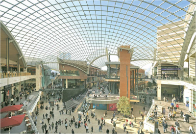
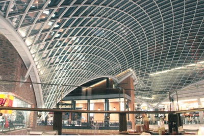
Cabot Circus is a 92,900m2 scheme incorporating free-form vaulted and shell shaped glass and steel roofs with a combined area of 5,850m2. The roofs are designed as a series of 10 interlocking undulating glazed panels, spanning up to 50m and 'floating' above the scheme. In total more than 2,800 individually sized 17.52mm thick laminated glass panes are set in elegant steel grillages.
As the building design progressed the proposed roofs became divorced from the intended building elevations. The structural design was complex and involved re-aligning the roof geometry with the building development without compromising the artistic intent, and also tracking the architect’s elevations and achieving support from adjacent structures. Structural optimisation of the central atrium by form finding resulted in geometry that was reasonably spherical. Rationalising the grid to fit a pure geometric surface such as a sphere or torus offered a number of advantages. The grid has a degree of repetition that provided fabrication benefits, particularly in controlling fabrication and erection tolerances. The glazing has a similar repetition to benefit the ordering and future ordering of glazing components. The toroidal grid that was chosen provides an aesthetic, practical and structurally economic solution. The other nine street roofs that form part of the scheme use barrel vaulted geometry.
The atrium roof is carried by five buildings and has the potential for differential movements across its supports. The atrium is also the most slender of the roof shells and has a maximum span of 55m and an average span of 40m.
The buckling capacity of the structure was carefully assessed and the significance of all second-order effects was considered.
The design solution lay in a rigorous study considering imperfect geometric models and full non-linear analysis to determine the critical buckling loads and appropriate design forces. The atrium structure has a minimum buckling factor of 2.95 times the worst case of dead and imposed ULS loading, which is not surprising given a grid of 80mm wide x 120mm deep RHS structural sections that span more than 40m.
Another significant consideration was the support conditions. Each of the roofs is supported by independent structures at each side of the street in the case of the barrel vaults and by five discreet buildings around the perimeter of the atrium. The glazed structures are designed to accommodate movements of the supporting buildings. Elastic supports were determined and then used in the calculation of all subsequent design forces, global capacities and support reactions. Each support is pin jointed using a sliding bearing to avoid transferring differential temperature loads and shearing forces between the buildings and roofs. The centre of each bearing has a spherical component which allows a degree of angular tolerance between the roof canopies and the buildings; this ensures that the bearings cannot bind with differential movements.
The expertise of the steelwork contractor determined the most practical way to fabricate and erect the structure to the necessary tight tolerances. The engineering design required the connections to be welded. The atrium roof was fabricated by cutting the tubular steel with square ends and then welding to precision machined solid nodes. The roofs were divided into transportable 'ladder' frames that were two bays wide and approximately nine bays in length. The fabrication of the toroidal geometry was closely controlled through precise jigs constructed off-site by the steelwork contractor. The tolerance of the fabrication and construction of a frame of this form was essential to the success and quality of the roof.
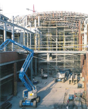
The fabricated frames were craned onto a full birdcage scaffold covering the entire 2,000m2 of the atrium. On completion of the internal grid, the 355mm diameter circular edge frame, incorporating a 450mm wide walk-in gutter profile was positioned and securely supported on the scaffold. The perimeter members were also welded connecting the internal grid and the boundary elements. A number of surveys were carried out throughout the assembly of the roofs to ensure the roof nodes were kept within specified +/- 20mm tolerance for any node position.
Each roof was modelled using cutting-edge 3D software and the lotting and nesting of the materials was carried out using this 3D model which significantly reduced the waste material onsite. Waste was recycled to make jigs for future projects or used to manufacture any new sections of the structure.
On completion of the steelwork, a full survey was carried out before glazing began. The glass is a single glazed system comprising a laminate of two heat strengthened 8mm panes. Each unit is fabricated as a 1.5m2 (approximately) panel edge supported over a silicone gasket with stainless steel discs clamping the glass at each node against wind uplift. The glass is a low-iron composition exhibiting the highest possible visual transparency.
Cabot Circus was opened to the public in September 2008, as programmed. Since the opening, Cabot Circus has received an 'Excellent' BREEAM rating for its low energy features including LED lighting to the streets and natural ventilation of the unconditioned streetscape.
| Architect | Chapman Taylor Benoy |
| Artist for the roof forms | Nayan Kulkarni |
| Structural Engineer | SKM Anthony Hunts |
| Steelwork Contractor | S H Structures Ltd. |
| Main Contractor | Sir Robert McAlpine Ltd. |
| Client | The Bristol Alliance |
Judges' comments
The mixed styles of this retail development are unified by a series of spectacular glazed roofs in various shell and vaulted forms. The structural design is an intelligent re-engineering of the initial concept. By rationalising the geometry and detailing for maximum repetition the fabrication, erection and glazing were all simplified.
Design and execution of very high quality.


