Difference between revisions of "Sheppey Crossing"
| Line 6: | Line 6: | ||
The decision to [[Design_for_steel_bridge_construction#Launching|launch]] the vast majority of the structure (15 spans in three phases using 14 separate launches) heavily influenced the design and also reduced the work load done by large capacity [[Design_for_steel_bridge_construction#Erection using cranes|mobile cranes]] during the [[Design_for_steel_bridge_construction|construction]] phase. The design programme mirrored the construction programme closely so that the release of deliverables allowed timely procurement and [[Design_for_steel_bridge_construction#Fabricating the steelwork|fabrication of the steelwork]] therefore avoiding congestion both in the works and at site. | The decision to [[Design_for_steel_bridge_construction#Launching|launch]] the vast majority of the structure (15 spans in three phases using 14 separate launches) heavily influenced the design and also reduced the work load done by large capacity [[Design_for_steel_bridge_construction#Erection using cranes|mobile cranes]] during the [[Design_for_steel_bridge_construction|construction]] phase. The design programme mirrored the construction programme closely so that the release of deliverables allowed timely procurement and [[Design_for_steel_bridge_construction#Fabricating the steelwork|fabrication of the steelwork]] therefore avoiding congestion both in the works and at site. | ||
| − | {{#image_template:image=File:Sheppey- | + | {{#image_template:image=File:Sheppey-1.jpg|align=left|wrap=true|width=400}} |
The four [[Ladder_deck_composite_bridges#Main girders|main girders]] at 5.5m centres continuously varied in depth from approximately 1.5m at the abutments to 3.5m over the central navigation channel. 940mm deep [[Ladder_deck_composite_bridges#Cross girders|cross girders]] at 3.5m longitudinal centres were [[Design_for_steel_bridge_construction#Fabricating the steelwork|fabricated]] in long lengths and then cut to the required length to suit Fairfield-Mabey's [[Design_for_steel_bridge_construction#Assembly|automated processes]]. [[Bracing_systems#Plan bracing|Plan bracing]] to the central seven spans located between the two inner [[Ladder_deck_composite_bridges#Main girders|main girders]] ensured temporary stability during the launch and acceptable aerodynamic behaviour of the completed deck. The [[Bracing_systems#Plan bracing|plan bracing]] was located at an aesthetically pleasing 300mm above the bottom flanges. [[Material_selection_and_product_specification|Material grades]] used were S355J2+N (6 to 61mm) supplemented with S355 K2 (62 to 77mm) and NL (78 to 98mm) as necessary. Over 185,000 [[Connections_in_bridges#Bolted connections|High Strength Friction Grip bolts]] were used in the structural [[Connections_in_bridges|connections]], totalling approximately 100 tonnes in weight. | The four [[Ladder_deck_composite_bridges#Main girders|main girders]] at 5.5m centres continuously varied in depth from approximately 1.5m at the abutments to 3.5m over the central navigation channel. 940mm deep [[Ladder_deck_composite_bridges#Cross girders|cross girders]] at 3.5m longitudinal centres were [[Design_for_steel_bridge_construction#Fabricating the steelwork|fabricated]] in long lengths and then cut to the required length to suit Fairfield-Mabey's [[Design_for_steel_bridge_construction#Assembly|automated processes]]. [[Bracing_systems#Plan bracing|Plan bracing]] to the central seven spans located between the two inner [[Ladder_deck_composite_bridges#Main girders|main girders]] ensured temporary stability during the launch and acceptable aerodynamic behaviour of the completed deck. The [[Bracing_systems#Plan bracing|plan bracing]] was located at an aesthetically pleasing 300mm above the bottom flanges. [[Material_selection_and_product_specification|Material grades]] used were S355J2+N (6 to 61mm) supplemented with S355 K2 (62 to 77mm) and NL (78 to 98mm) as necessary. Over 185,000 [[Connections_in_bridges#Bolted connections|High Strength Friction Grip bolts]] were used in the structural [[Connections_in_bridges|connections]], totalling approximately 100 tonnes in weight. | ||
By using modern fabrication facilities and forging a team of the designers, main contractor and steelwork contractor, the high level bridge was [[Design_for_steel_bridge_construction#Fabricating the steelwork|fabricated]] and [[Design_for_steel_bridge_construction#Bridge erection|erected]] within programme and budget. Over 11,000 tonnes of permanent and temporary steelwork went into the construction of this landmark structure that was efficiently [[Design_for_steel_bridge_construction#Bridge erection|erected]] between December 2004 and December 2005, bringing substantial benefit to the local community. | By using modern fabrication facilities and forging a team of the designers, main contractor and steelwork contractor, the high level bridge was [[Design_for_steel_bridge_construction#Fabricating the steelwork|fabricated]] and [[Design_for_steel_bridge_construction#Bridge erection|erected]] within programme and budget. Over 11,000 tonnes of permanent and temporary steelwork went into the construction of this landmark structure that was efficiently [[Design_for_steel_bridge_construction#Bridge erection|erected]] between December 2004 and December 2005, bringing substantial benefit to the local community. | ||
| − | {{#image_template:image=File:Sheppey- | + | {{#image_template:image=File:Sheppey-2.jpg|align=right|wrap=true|width=300}} |
{|class="wikitable" width="500" | {|class="wikitable" width="500" | ||
|- | |- | ||
Revision as of 12:16, 12 March 2019
Structural Steel Design Awards 2007 - Winner
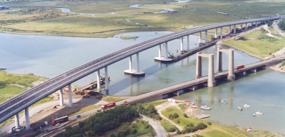
The completion of the new 'Sheppey Crossing' in 2006 has provided the first fixed link from mainland Kent to the Isle of Sheppey, a high level viaduct. The viaduct was constructed as the primary feature of the Highways Agency DBFO Contract. The A249 dual carriageway now enables free flow of traffic. The bridge, which uses 10,000 tonnes of fabricated steel plate girders and 60,000 tonnes of structural concrete, is 1,270m long with 19 spans, the longest being 92.5m over the central navigation Channel of the Swale. The spans grow in length gradually from the abutments towards the main central span and the bridge depth increases proportionately to a maximum of nearly 4m at mid crossing. This unusual arrangement produces a most elegant elevation, which is enhanced by the sweeping curve of the highway rising to a crest of 30m above the estuary.
The bridge spans over the Saxon shoreway and due to the flat terrain there is a visual impact envelope of up to 30km. The flora and fauna in the area directly affected by the build were relocated to other parts of the marsh site.
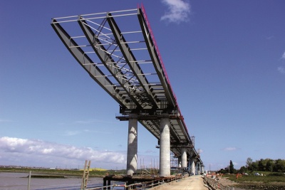
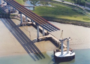
The decision to launch the vast majority of the structure (15 spans in three phases using 14 separate launches) heavily influenced the design and also reduced the work load done by large capacity mobile cranes during the construction phase. The design programme mirrored the construction programme closely so that the release of deliverables allowed timely procurement and fabrication of the steelwork therefore avoiding congestion both in the works and at site.
The four main girders at 5.5m centres continuously varied in depth from approximately 1.5m at the abutments to 3.5m over the central navigation channel. 940mm deep cross girders at 3.5m longitudinal centres were fabricated in long lengths and then cut to the required length to suit Fairfield-Mabey's automated processes. Plan bracing to the central seven spans located between the two inner main girders ensured temporary stability during the launch and acceptable aerodynamic behaviour of the completed deck. The plan bracing was located at an aesthetically pleasing 300mm above the bottom flanges. Material grades used were S355J2+N (6 to 61mm) supplemented with S355 K2 (62 to 77mm) and NL (78 to 98mm) as necessary. Over 185,000 High Strength Friction Grip bolts were used in the structural connections, totalling approximately 100 tonnes in weight.
By using modern fabrication facilities and forging a team of the designers, main contractor and steelwork contractor, the high level bridge was fabricated and erected within programme and budget. Over 11,000 tonnes of permanent and temporary steelwork went into the construction of this landmark structure that was efficiently erected between December 2004 and December 2005, bringing substantial benefit to the local community.
| Architect | Yee Associates |
| Lead Designer | Capita Symonds |
| Viaduct Structural Engineer | Cass Hayward LLP |
| Steelwork Contractor | Mabey Bridge Ltd. |
| Main Contractor | Carillion |
| Client | Highways Agency and Sheppy Route Ltd |
Judges' comments
The new road bridge replaces the previous road/rail lifting bridge, and provides much-needed improved access to the Isle of Sheppey.
For ship passage, the structure is some 30 metres high, but the team have achieved a solution which minimises intrusion into the flat landscape. The main plate girders carry cross-beams within their depth, and they taper continuously from abutments to mid-span, both in plan and elevation. The structure was launched from the north end, probably the longest of such operations. Having solved the primary challenges, the team have then refined the design to its successful conclusion.


