Difference between revisions of "Design using structural fire standards"
| (18 intermediate revisions by 2 users not shown) | |||
| Line 1: | Line 1: | ||
__SECTIONLINKTOTOP__ | __SECTIONLINKTOTOP__ | ||
| + | {{#image_template:image=File:P375.png|link=https://www.steelconstruction.info/images/5/5e/SCI_P375.pdf|caption=[[Media:SCI_P375.pdf|SCI P375]]: Guidance on fire Eurocodes|align=right|wrap=true|width=300}} | ||
Both [[Design_using_structural_fire_standards#BS 5950_Part_8|BS 5950 Part 8]]<ref name="No1"> BS 5950-8: 2003, Structural use of steelwork in buildings. Code of practice for fire resistant design. BSI</ref> and [[Design_using_structural_fire_standards#Fire_Eurocodes|Eurocodes]] are available for the design of structural steel in fire in the UK. The [[Design_using_structural_fire_standards#Fire_Eurocodes|Eurocodes]] suite consists of: BS EN 1991-1-2<ref name="No2"> BS EN 1991-1-2: 2002, Eurocode 1. Actions on Structures. General actions. Actions on structures exposed to fire. BSI</ref>, BS EN 1993-1-2<ref name="No3"> BS EN 1993-1-2: 2005, Eurocode 3. Design of steel structures. General rules. Structural fire design. BSI</ref> and BS EN 1994-1-2<ref name="No4"> BS EN 1994-1-2: 2005 +A1:2014, Eurocode 4. Design of composite steel and concrete structures. General rules. Structural fire design. BSI</ref>. These codes concern themselves mainly with the design of individual elements of construction in fire. The behaviour of frames and assemblies in fire is usually dealt with using advanced [[Structural_fire_engineering|fire engineering]] methods. | Both [[Design_using_structural_fire_standards#BS 5950_Part_8|BS 5950 Part 8]]<ref name="No1"> BS 5950-8: 2003, Structural use of steelwork in buildings. Code of practice for fire resistant design. BSI</ref> and [[Design_using_structural_fire_standards#Fire_Eurocodes|Eurocodes]] are available for the design of structural steel in fire in the UK. The [[Design_using_structural_fire_standards#Fire_Eurocodes|Eurocodes]] suite consists of: BS EN 1991-1-2<ref name="No2"> BS EN 1991-1-2: 2002, Eurocode 1. Actions on Structures. General actions. Actions on structures exposed to fire. BSI</ref>, BS EN 1993-1-2<ref name="No3"> BS EN 1993-1-2: 2005, Eurocode 3. Design of steel structures. General rules. Structural fire design. BSI</ref> and BS EN 1994-1-2<ref name="No4"> BS EN 1994-1-2: 2005 +A1:2014, Eurocode 4. Design of composite steel and concrete structures. General rules. Structural fire design. BSI</ref>. These codes concern themselves mainly with the design of individual elements of construction in fire. The behaviour of frames and assemblies in fire is usually dealt with using advanced [[Structural_fire_engineering|fire engineering]] methods. | ||
Although both codes are quite different in scope and complexity, they are based on a common understanding of the [[Design_using_structural_fire_standards#Steelwork_strength_in_fire|strength of structural steel in fire]] and also the factors which affect inherent fire resistance. | Although both codes are quite different in scope and complexity, they are based on a common understanding of the [[Design_using_structural_fire_standards#Steelwork_strength_in_fire|strength of structural steel in fire]] and also the factors which affect inherent fire resistance. | ||
| − | + | [[Design_using_structural_fire_standards#BS 5950_Part_8|BS 5950 Part 8]]<ref name="No1"></ref> was withdrawn in 2017, but may still be used according to the UK building Regulations. | |
| − | + | ||
==Steelwork strength in fire== | ==Steelwork strength in fire== | ||
| Line 12: | Line 13: | ||
==Effect of temperature profile== | ==Effect of temperature profile== | ||
A joint test programme by Tata Steel (then British Steel) and the Building Research Establishment showed that the temperature profile (i.e. the variation in temperature) through the cross-section of a steel structural member has a marked effect on its performance in fire. The basic high temperature strength curve shown above has been generated by testing a series of small samples of steel in the laboratory, where the whole of each test sample is at a uniform temperature and is axially loaded. | A joint test programme by Tata Steel (then British Steel) and the Building Research Establishment showed that the temperature profile (i.e. the variation in temperature) through the cross-section of a steel structural member has a marked effect on its performance in fire. The basic high temperature strength curve shown above has been generated by testing a series of small samples of steel in the laboratory, where the whole of each test sample is at a uniform temperature and is axially loaded. | ||
| − | When these conditions are repeated in a full scale member tests, for example, a loaded [[Fire_testing#The_standard_fire_test|fire test]] on a full scale [[Steel_construction_products#Standard_open_sections|column]] heated uniformly and supporting a load that produces a force or moment equal to 60% of its room temperature resistance, it will also fail at 550°C. But if | + | When these conditions are repeated in a full scale member tests, for example, a loaded [[Fire_testing#The_standard_fire_test|fire test]] on a full scale [[Steel_construction_products#Standard_open_sections|column]] heated uniformly and supporting a load that produces a force or moment equal to 60% of its room temperature resistance, it will also fail at 550°C. But if the section is not uniformly heated then, when the hotter part of the section reaches the temperature at which it will begin to yield plastically, it will transfer load to cooler regions of the section, which will still act elastically. As the temperature rises further, more load is transferred from the hot region by plastic yielding until eventually the load in the cool regions becomes so high that they too become plastic and the member fails. |
One of the most common situations in which temperature gradients have a significant effect on the fire resistance of structural steel is where [[Steel_construction_products#Standard_open_sections|beams]] support concrete slabs. The effect of the slab is both to protect the upper surface of the top flange from the fire and to act as a heat sink. This induces temperature differences of more than 200°C between the upper and lower flanges in standard [[Fire_testing#The_standard_fire_test|fire tests]]. Test data shows that the <u>limiting (lower flange) temperature</u> of fully loaded, [[Floor_systems#Precast_units|non-composite beams carrying concrete slabs]] is about 620°C. This compares with 550°C for [[Steel_construction_products#Standard_open_sections|beams]] exposed on all four sides. | One of the most common situations in which temperature gradients have a significant effect on the fire resistance of structural steel is where [[Steel_construction_products#Standard_open_sections|beams]] support concrete slabs. The effect of the slab is both to protect the upper surface of the top flange from the fire and to act as a heat sink. This induces temperature differences of more than 200°C between the upper and lower flanges in standard [[Fire_testing#The_standard_fire_test|fire tests]]. Test data shows that the <u>limiting (lower flange) temperature</u> of fully loaded, [[Floor_systems#Precast_units|non-composite beams carrying concrete slabs]] is about 620°C. This compares with 550°C for [[Steel_construction_products#Standard_open_sections|beams]] exposed on all four sides. | ||
| − | <gallery caption="Effects of temperature profile on limiting temperatures " widths=250px heights=250px> | + | <gallery caption="Effects of temperature profile on limiting temperatures " perrow=2 widths=250px heights=250px> |
| − | Image:Load_ratio_and_temperature_1.png | A [[Design_using_structural_fire_standards#Effect_of_load|fully loaded]] | + | Image:Load_ratio_and_temperature_1.png | A [[Design_using_structural_fire_standards#Effect_of_load|fully loaded]] 533x210UB82 exposed on 4 sides fails in a [[Fire_testing|BS 476 Part 20]]<ref name="No5"> BS 476-20: 1987, Fire tests on building materials and structures. Method for determination of the fire resistance of elements of construction (general principles). BSI</ref> fire test when the temperature reaches 550°C. This occurs after about 16 minutes |
| − | Image:Load_ratio_and _temperature_2.png| A [[Design_using_structural_fire_standards#Effect_of_load|fully loaded]] non-composite | + | Image:Load_ratio_and _temperature_2.png| A [[Design_using_structural_fire_standards#Effect_of_load|fully loaded]] non-composite 533x210UB82 exposed on 3 sides fails in a [[Fire_testing|BS 476 Part 20]]<ref name="No5"></ref> fire test when the bottom flange temperature reaches 620°C. This occurs after about 18.5 minutes |
| + | </gallery> | ||
| + | <br> | ||
==Effect of load== | ==Effect of load== | ||
| − | It is known from full scale fire tests that a simply supported hot rolled [[Steel_construction_products#Standard_open_sections|beam]] carrying a concrete floor slab and 60% of its room temperature | + | It is known from full scale fire tests that a simply supported hot rolled [[Steel_construction_products#Standard_open_sections|beam]] carrying a concrete floor slab and 60% of its room temperature resistance will collapse when the bottom flange temperature reaches 620°C. It is also known that if it carries a lower load then plasticity will occur at a higher temperature. Because it will take the [[Steel_construction_products#Standard_open_sections|beam]] a longer time to reach the higher temperature, it can be seen that reducing loads will enable a structural member to fulfil its structural function for a longer period in a fire. |
In [[Design_using_structural_fire_standards#BS 5950_Part_8|BS 5950 Part 8]]<ref name="No1"></ref>, member utilisation is expressed in terms of the ‘Load ratio’ where: | In [[Design_using_structural_fire_standards#BS 5950_Part_8|BS 5950 Part 8]]<ref name="No1"></ref>, member utilisation is expressed in terms of the ‘Load ratio’ where: | ||
| − | Load ratio = | + | Load ratio = the load at the fire limit state divided by the load resistance at 20°C |
The load ratio is calculated using load factors given in [[Design_using_structural_fire_standards#BS 5950_Part_8|BS 5950 Part 8]]<ref name="No1"></ref> which reflect the fact that fire is an accidental limit state and that extremes of fire and extremes of load are unlikely to occur simultaneously. Consequently, the dead load factor in fire is 1.0 and the live load factor is 0.8 (0.5 in offices). | The load ratio is calculated using load factors given in [[Design_using_structural_fire_standards#BS 5950_Part_8|BS 5950 Part 8]]<ref name="No1"></ref> which reflect the fact that fire is an accidental limit state and that extremes of fire and extremes of load are unlikely to occur simultaneously. Consequently, the dead load factor in fire is 1.0 and the live load factor is 0.8 (0.5 in offices). | ||
| Line 33: | Line 36: | ||
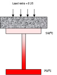
Where the load ratio is 0.25 for example, failure in [[Floor_systems#Precast_units|simply supported beams carrying non-composite concrete slabs]] will not occur until the bottom flange of the [[Steel_construction_products#Standard_open_sections|beam]] reaches 750°C, an increase of 130°C on the [[Design_using_structural_fire_standards#Effect_of_temperature_profile|limiting temperature]] in the fully loaded case. | Where the load ratio is 0.25 for example, failure in [[Floor_systems#Precast_units|simply supported beams carrying non-composite concrete slabs]] will not occur until the bottom flange of the [[Steel_construction_products#Standard_open_sections|beam]] reaches 750°C, an increase of 130°C on the [[Design_using_structural_fire_standards#Effect_of_temperature_profile|limiting temperature]] in the fully loaded case. | ||
[[Design_using_structural_fire_standards#Fire_Eurocodes|BS EN 1993-1-2]]<ref name="No3"></ref> adopts a similar approach although load ratio is replaced by utilisation factor. | [[Design_using_structural_fire_standards#Fire_Eurocodes|BS EN 1993-1-2]]<ref name="No3"></ref> adopts a similar approach although load ratio is replaced by utilisation factor. | ||
| − | <gallery caption="Effects of temperature profile and load on limiting temperatures " widths=250px heights=250px> | + | <gallery caption="Effects of temperature profile and load on limiting temperatures " perrow=2 widths=250px heights=250px> |
| − | Image:Load_ratio_and_temperature_1.png | A fully loaded | + | Image:Load_ratio_and_temperature_1.png | A fully loaded 533x210UB82 exposed on 4 sides fails in a [[Fire_testing|BS 476 Part 20]]<ref name="No5"></ref> fire test when the temperature 550°C. This occurs after about 16 minutes |
| − | Image:Load_ratio_and _temperature_2.png| A fully loaded non-composite | + | Image:Load_ratio_and _temperature_2.png| A fully loaded non-composite 533x210UB82 exposed on 3 sides fails in a [[Fire_testing|BS 476 Part 20]]<ref name="No5"></ref> fire test when the bottom flange temperature reaches 620°C. This occurs after about 18.5 minutes |
| − | Image:Load_ratio_and _temperature_3.png| | + | Image:Load_ratio_and _temperature_3.png| A partially loaded non-composite 533x210UB82 exposed on 3 sides fails in a [[Fire_testing|BS 476 Part 20]]<ref name="No5"></ref> fire test when the bottom flange temperature reaches 750°C . This occurs after about 31 minutes |
</gallery> | </gallery> | ||
| + | <br> | ||
==BS 5950 Part 8== | ==BS 5950 Part 8== | ||
BS 5950 Part 8<ref name="No1"></ref> was first published in 1990 and redrafted in 2003. It brings together in one document many of the methods of achieving fire resistance for structural steelwork. Although it is based on evaluation of performance of structural steel members exposed to the [[Fire_testing#The_standard_fire_test|standard fire curve]] as defined in [[Fire_testing|BS 476 Part 20]]<ref name="No5"></ref>, it may also be used in [[Structural_fire_engineering|fire engineering]] assessments when [[Structural_fire_engineering#Predicting_the_temperature_of_the_compartment|predicted fire temperatures]] are derived by calculation. | BS 5950 Part 8<ref name="No1"></ref> was first published in 1990 and redrafted in 2003. It brings together in one document many of the methods of achieving fire resistance for structural steelwork. Although it is based on evaluation of performance of structural steel members exposed to the [[Fire_testing#The_standard_fire_test|standard fire curve]] as defined in [[Fire_testing|BS 476 Part 20]]<ref name="No5"></ref>, it may also be used in [[Structural_fire_engineering|fire engineering]] assessments when [[Structural_fire_engineering#Predicting_the_temperature_of_the_compartment|predicted fire temperatures]] are derived by calculation. | ||
BS 5950 Part 8<ref name="No1"></ref> also includes design information and guidance for design of [[Portal_frames|portal frames]], hollow sections, [[Fire_and steel_construction#External_steelwork_in_fire|external steelwork]] , [[Design_of_composite_steel_deck_floors_for_fire|composite floors]] and calculation of protection thicknesses based on [[Design_using_structural_fire_standards#Steelwork_strength_in_fire|limiting temperatures]]. The code contains two basic approaches to assessment of fire resistance either by test or by calculation. | BS 5950 Part 8<ref name="No1"></ref> also includes design information and guidance for design of [[Portal_frames|portal frames]], hollow sections, [[Fire_and steel_construction#External_steelwork_in_fire|external steelwork]] , [[Design_of_composite_steel_deck_floors_for_fire|composite floors]] and calculation of protection thicknesses based on [[Design_using_structural_fire_standards#Steelwork_strength_in_fire|limiting temperatures]]. The code contains two basic approaches to assessment of fire resistance either by test or by calculation. | ||
| − | A commentary to the 1990 version of the standard giving more detailed information and worked examples, is provided in [[#Resources|SCI P080]]. | + | A commentary to the 1990 version of the standard, giving more detailed information and worked examples, is provided in [[#Resources|SCI P080]]. |
==Fire Eurocodes== | ==Fire Eurocodes== | ||
| Line 49: | Line 53: | ||
The Eurocodes that describe the rules for the fire design of buildings using structural steelwork are: BS EN 1991-1-2<ref name="No2"></ref>, BS EN 1993-1-2<ref name="No3"></ref> and BS EN 1994-1-2<ref name="No4"></ref>. | The Eurocodes that describe the rules for the fire design of buildings using structural steelwork are: BS EN 1991-1-2<ref name="No2"></ref>, BS EN 1993-1-2<ref name="No3"></ref> and BS EN 1994-1-2<ref name="No4"></ref>. | ||
| − | Each member state is required to publish a National Annex to each part of the Eurocode. The National Annex may only contain information on those parameters which are left open in the Eurocode for national choice, known as Nationally Determined Parameters. The National Annex may also contain guidance on the application of informative annexes in the Eurocode and references to non-contradictory complementary information to assist the user to apply the design rules in the Eurocode | + | Each member state is required to publish a National Annex to each part of the Eurocode. The National Annex may only contain information on those parameters which are left open in the Eurocode for national choice, known as Nationally Determined Parameters. The National Annex may also contain guidance on the application of informative annexes in the Eurocode and references to non-contradictory complementary information to assist the user to apply the design rules in the Eurocode. |
| − | The fire Eurocodes <ref name="No2"></ref> <ref name="No3"></ref> <ref name="No4"></ref> have a wider scope than [[Design_using_structural_fire_standards#BS 5950_Part_8|BS 5950 Part 8]]<ref name="No1"></ref>. They open up a number of new design possibilities including the use of | + | The fire Eurocodes <ref name="No2"></ref> <ref name="No3"></ref> <ref name="No4"></ref> have a wider scope than [[Design_using_structural_fire_standards#BS 5950_Part_8|BS 5950 Part 8]]<ref name="No1"></ref>. They open up a number of new design possibilities including the use of the [[Structural_fire_engineering#Parametric_time-temperature_relationships|parametric time-temperature curve]]. This is a mechanism of calculating the actual time-temperature relationship in a compartment of known dimensions and occupancy and removes historic dependence on the [[Fire_testing#The_standard_fire_test|standard fire test]]. It is a major advance in the development of performance based design and forms the basis of the methods used to determine the fire resistance periods in [[Structural_fire_resistance_requirements#BS_9999|BS 9999]]<ref name="No6">BS 9999: 2017, Fire safety in the design, management and use of buildings - Code of practice. BSI</ref>. |
It should be noted that the Eurocodes have introduced the concept of [[Member_design#Classification_of_cross_sections|section classification]] into fire design, something that was absent from [[Design_using_structural_fire_standards#BS_5950_Part_8|BS 5950 Part 8]]<ref name="No1"></ref>. Guidance on this is available by clicking [[Eurocode_classification_of_sections_in_fire|here]]. In certain situations, it is possible for [[Member_design#Classification_of_cross_sections|section classification]] to change between ambient and fire design and this may have an effect on the [[Design_using_structural_fire_standards#Effect_of_temperature_profile|limiting temperature]]. | It should be noted that the Eurocodes have introduced the concept of [[Member_design#Classification_of_cross_sections|section classification]] into fire design, something that was absent from [[Design_using_structural_fire_standards#BS_5950_Part_8|BS 5950 Part 8]]<ref name="No1"></ref>. Guidance on this is available by clicking [[Eurocode_classification_of_sections_in_fire|here]]. In certain situations, it is possible for [[Member_design#Classification_of_cross_sections|section classification]] to change between ambient and fire design and this may have an effect on the [[Design_using_structural_fire_standards#Effect_of_temperature_profile|limiting temperature]]. | ||
| Line 71: | Line 75: | ||
<br> | <br> | ||
Member fire design tools:<br> | Member fire design tools:<br> | ||
| − | *[[Design software and tools#Resistance of | + | *[[Design software and tools#Resistance of beams at elevated temperature|Resistance of beams at elevated temperature]] |
| − | *[[Design software and tools#Resistance of | + | *[[Design software and tools#Resistance of columns at elevated temperature|Resistance of columns at elevated temperature]] |
==See also== | ==See also== | ||
Latest revision as of 15:25, 21 June 2022
Both BS 5950 Part 8[1] and Eurocodes are available for the design of structural steel in fire in the UK. The Eurocodes suite consists of: BS EN 1991-1-2[2], BS EN 1993-1-2[3] and BS EN 1994-1-2[4]. These codes concern themselves mainly with the design of individual elements of construction in fire. The behaviour of frames and assemblies in fire is usually dealt with using advanced fire engineering methods.
Although both codes are quite different in scope and complexity, they are based on a common understanding of the strength of structural steel in fire and also the factors which affect inherent fire resistance. BS 5950 Part 8[1] was withdrawn in 2017, but may still be used according to the UK building Regulations.
[top]Steelwork strength in fire
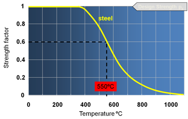
All materials become weaker when they get hot. The strength of steel at high temperature has been defined in great detail and it is known that at a temperature of 550°C, hot rolled structural steel will retain 60% of its room temperature load capacity. This is important because, before the introduction of limit state design concepts, permissible stress was used as a basis for design. In this approach, the maximum stress allowed in a member was about 60% of its room temperature strength. This led to the commonly held assumption that 550°C was the highest (limiting) temperature that a steel structure would withstand before collapse. Research has shown, however, that the limiting temperature of a structural steel member is not fixed at 550°C but varies according to two factors, the temperature profile and the load.
[top]Effect of temperature profile
A joint test programme by Tata Steel (then British Steel) and the Building Research Establishment showed that the temperature profile (i.e. the variation in temperature) through the cross-section of a steel structural member has a marked effect on its performance in fire. The basic high temperature strength curve shown above has been generated by testing a series of small samples of steel in the laboratory, where the whole of each test sample is at a uniform temperature and is axially loaded. When these conditions are repeated in a full scale member tests, for example, a loaded fire test on a full scale column heated uniformly and supporting a load that produces a force or moment equal to 60% of its room temperature resistance, it will also fail at 550°C. But if the section is not uniformly heated then, when the hotter part of the section reaches the temperature at which it will begin to yield plastically, it will transfer load to cooler regions of the section, which will still act elastically. As the temperature rises further, more load is transferred from the hot region by plastic yielding until eventually the load in the cool regions becomes so high that they too become plastic and the member fails.
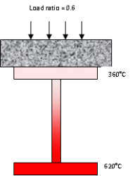
One of the most common situations in which temperature gradients have a significant effect on the fire resistance of structural steel is where beams support concrete slabs. The effect of the slab is both to protect the upper surface of the top flange from the fire and to act as a heat sink. This induces temperature differences of more than 200°C between the upper and lower flanges in standard fire tests. Test data shows that the limiting (lower flange) temperature of fully loaded, non-composite beams carrying concrete slabs is about 620°C. This compares with 550°C for beams exposed on all four sides.
- Effects of temperature profile on limiting temperatures
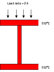
A fully loaded 533x210UB82 exposed on 4 sides fails in a BS 476 Part 20[5] fire test when the temperature reaches 550°C. This occurs after about 16 minutes
A fully loaded non-composite 533x210UB82 exposed on 3 sides fails in a BS 476 Part 20[5] fire test when the bottom flange temperature reaches 620°C. This occurs after about 18.5 minutes
[top]Effect of load
It is known from full scale fire tests that a simply supported hot rolled beam carrying a concrete floor slab and 60% of its room temperature resistance will collapse when the bottom flange temperature reaches 620°C. It is also known that if it carries a lower load then plasticity will occur at a higher temperature. Because it will take the beam a longer time to reach the higher temperature, it can be seen that reducing loads will enable a structural member to fulfil its structural function for a longer period in a fire. In BS 5950 Part 8[1], member utilisation is expressed in terms of the ‘Load ratio’ where:
Load ratio = the load at the fire limit state divided by the load resistance at 20°C
The load ratio is calculated using load factors given in BS 5950 Part 8[1] which reflect the fact that fire is an accidental limit state and that extremes of fire and extremes of load are unlikely to occur simultaneously. Consequently, the dead load factor in fire is 1.0 and the live load factor is 0.8 (0.5 in offices).
It is normally considered that a fully loaded section has a load ratio of 0.6. This comes from an analysis of the live and dead load factors for ambient(1.4 and 1.6 respectively) and fire design.
(1.0 + 0.8)/(1.4 + 1.6) = 0.6
Where the load ratio is 0.25 for example, failure in simply supported beams carrying non-composite concrete slabs will not occur until the bottom flange of the beam reaches 750°C, an increase of 130°C on the limiting temperature in the fully loaded case. BS EN 1993-1-2[3] adopts a similar approach although load ratio is replaced by utilisation factor.
- Effects of temperature profile and load on limiting temperatures
A fully loaded 533x210UB82 exposed on 4 sides fails in a BS 476 Part 20[5] fire test when the temperature 550°C. This occurs after about 16 minutes
A fully loaded non-composite 533x210UB82 exposed on 3 sides fails in a BS 476 Part 20[5] fire test when the bottom flange temperature reaches 620°C. This occurs after about 18.5 minutes
A partially loaded non-composite 533x210UB82 exposed on 3 sides fails in a BS 476 Part 20[5] fire test when the bottom flange temperature reaches 750°C . This occurs after about 31 minutes
[top]BS 5950 Part 8
BS 5950 Part 8[1] was first published in 1990 and redrafted in 2003. It brings together in one document many of the methods of achieving fire resistance for structural steelwork. Although it is based on evaluation of performance of structural steel members exposed to the standard fire curve as defined in BS 476 Part 20[5], it may also be used in fire engineering assessments when predicted fire temperatures are derived by calculation. BS 5950 Part 8[1] also includes design information and guidance for design of portal frames, hollow sections, external steelwork , composite floors and calculation of protection thicknesses based on limiting temperatures. The code contains two basic approaches to assessment of fire resistance either by test or by calculation. A commentary to the 1990 version of the standard, giving more detailed information and worked examples, is provided in SCI P080.
[top]Fire Eurocodes
The Commission of the European Community began work on the harmonisation of technical specifications for construction in 1975, with the objective of eliminating technical obstacles to trade between member states. Part of this programme of work was the development of a set of harmonised technical rules, the Eurocodes, for the design of construction works, which in the first instance would provide an alternative to national design rules and, ultimately would replace them.
The Eurocodes that describe the rules for the fire design of buildings using structural steelwork are: BS EN 1991-1-2[2], BS EN 1993-1-2[3] and BS EN 1994-1-2[4].
Each member state is required to publish a National Annex to each part of the Eurocode. The National Annex may only contain information on those parameters which are left open in the Eurocode for national choice, known as Nationally Determined Parameters. The National Annex may also contain guidance on the application of informative annexes in the Eurocode and references to non-contradictory complementary information to assist the user to apply the design rules in the Eurocode.
The fire Eurocodes [2] [3] [4] have a wider scope than BS 5950 Part 8[1]. They open up a number of new design possibilities including the use of the parametric time-temperature curve. This is a mechanism of calculating the actual time-temperature relationship in a compartment of known dimensions and occupancy and removes historic dependence on the standard fire test. It is a major advance in the development of performance based design and forms the basis of the methods used to determine the fire resistance periods in BS 9999[6].
It should be noted that the Eurocodes have introduced the concept of section classification into fire design, something that was absent from BS 5950 Part 8[1]. Guidance on this is available by clicking here. In certain situations, it is possible for section classification to change between ambient and fire design and this may have an effect on the limiting temperature.
A guide to the fire Eurocodes, SCI P375, has been published by the Steel Construction Institute. Simple member fire design tools for the calculation of limiting temperatures, (called critical temperatures in the Eurocodes) of protected and unprotected non-composite, restained beams and axially loaded protected and unprotected columns are available. In addition, two design examples which illustate the design procedures for protected and unprotected columns, and composite and non-composite beams in a two storey and a seven storey building can be accessed.
[top]References
- ↑ 1.0 1.1 1.2 1.3 1.4 1.5 1.6 1.7 BS 5950-8: 2003, Structural use of steelwork in buildings. Code of practice for fire resistant design. BSI
- ↑ 2.0 2.1 2.2 BS EN 1991-1-2: 2002, Eurocode 1. Actions on Structures. General actions. Actions on structures exposed to fire. BSI
- ↑ 3.0 3.1 3.2 3.3 BS EN 1993-1-2: 2005, Eurocode 3. Design of steel structures. General rules. Structural fire design. BSI
- ↑ 4.0 4.1 4.2 BS EN 1994-1-2: 2005 +A1:2014, Eurocode 4. Design of composite steel and concrete structures. General rules. Structural fire design. BSI
- ↑ 5.0 5.1 5.2 5.3 5.4 5.5 BS 476-20: 1987, Fire tests on building materials and structures. Method for determination of the fire resistance of elements of construction (general principles). BSI
- ↑ BS 9999: 2017, Fire safety in the design, management and use of buildings - Code of practice. BSI
[top]Further reading
- ECCS Eurocode Design Manuals: Fire Design of Steel Structures. Franssen, J-M & Vial Real, P.
[top]Resources
- SCI P375 Fire Resistance Design of Steel Framed Buildings, 2012
- Steel construction - Fire Protection supplement, 2013
- SCI P080 Fire resistant design of steel structures – A handbook to BS 5950 Part 8, 1990.
- Design example for the calculation of critical temperatures for beams and columns in a two storey building
- Design example for the calculation of critical temperatures for beams and columns in a seven storey building
Member fire design tools:
[top]See also
- Eurocode classification of sections in fire
- Fire protecting structural steelwork
- Fire testing
- Structural fire engineering
- Structural fire resistance requirements


