Difference between revisions of "The Rose Bowl, West End, Southampton"
(Created page with "==Structural Steel Design Awards 2011 - Commendation== {{#image_template:image=File:L3_image.png|align=right|wrap=true|width=400}} The addition...") |
|||
| (One intermediate revision by the same user not shown) | |||
| Line 10: | Line 10: | ||
Above the two storey structure supported on the front column is the sickle rafter, which forms the main structural member to the canopy roof. This rafter curves round the back corner of the two storey structure forming an independent column which slopes back into the building. This column is discretely connected back to the two storey structure at roof and floor levels. The sickle rafter is formed of [[Steel_construction_products#Standard open sections|standard UB sections]] with the curved portion [[Steel_construction_products#Plate girders|formed in plates]]. | Above the two storey structure supported on the front column is the sickle rafter, which forms the main structural member to the canopy roof. This rafter curves round the back corner of the two storey structure forming an independent column which slopes back into the building. This column is discretely connected back to the two storey structure at roof and floor levels. The sickle rafter is formed of [[Steel_construction_products#Standard open sections|standard UB sections]] with the curved portion [[Steel_construction_products#Plate girders|formed in plates]]. | ||
| − | + | {{#image_template:image=File:Rose_Bowl-1.png|align=left|wrap=true|width=300}} | |
The structure in its final form is a simple [[Braced_frames|braced structure]] with the floor slabs acting as [[Braced_frames#Horizontal diaphragms|diaphragms]]. The main (canopy) roof is braced for the full length to ensure effective transfer of lateral loads. Provision of [[Braced_frames#Vertical bracing|vertical bracing]] was only possible longitudinally in the line of columns mid-span of the terrace rakers, and between the sickle columns to the rear of the building. No [[Braced_frames#Vertical bracing|vertical bracing]] was possible radially or in the walls of the ‘back of house structure’ due to the numerous openings and glazed areas. | The structure in its final form is a simple [[Braced_frames|braced structure]] with the floor slabs acting as [[Braced_frames#Horizontal diaphragms|diaphragms]]. The main (canopy) roof is braced for the full length to ensure effective transfer of lateral loads. Provision of [[Braced_frames#Vertical bracing|vertical bracing]] was only possible longitudinally in the line of columns mid-span of the terrace rakers, and between the sickle columns to the rear of the building. No [[Braced_frames#Vertical bracing|vertical bracing]] was possible radially or in the walls of the ‘back of house structure’ due to the numerous openings and glazed areas. | ||
| − | + | ||
The sickle columns are discretely connected at each floor level and at roof to the accommodation block, taking the form of a radial prop between the columns on each line. At two locations along the length of each stand diagonal members spring from the [[Steel_construction_products#Standard open sections|914 x 305 UB]] sickle columns to third points in the adjacent floor edge beams. By this means the sickle columns are discretely connected to the ‘building’ structure, maintaining the required architectural illusion of independence. Thus the [[Braced_frames#Vertical bracing|vertical bracing]] between the sickle columns provides the [[Concept_design#Structural options for stability|lateral stability]] to the rear of the building. | The sickle columns are discretely connected at each floor level and at roof to the accommodation block, taking the form of a radial prop between the columns on each line. At two locations along the length of each stand diagonal members spring from the [[Steel_construction_products#Standard open sections|914 x 305 UB]] sickle columns to third points in the adjacent floor edge beams. By this means the sickle columns are discretely connected to the ‘building’ structure, maintaining the required architectural illusion of independence. Thus the [[Braced_frames#Vertical bracing|vertical bracing]] between the sickle columns provides the [[Concept_design#Structural options for stability|lateral stability]] to the rear of the building. | ||
| Line 37: | Line 37: | ||
A good example of ‘less is more’. | A good example of ‘less is more’. | ||
| − | [[Category:Case studies | + | [[Category:Case studies - Leisure buildings]] |
Latest revision as of 12:14, 12 March 2019
Structural Steel Design Awards 2011 - Commendation
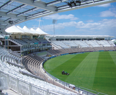
The addition of two new stands at The Rose Bowl cricket ground in Hampshire has increased capacity from 20,000 to 25,000, making it one of the largest grounds in the country. The number of permanent seats increased to 15,000.
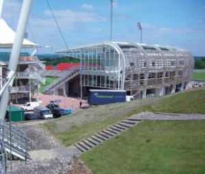
Keen to ensure that the new stands fitted the original visual concept for the ground, a sickle structure was developed visually separating the roof to the permanent seating from the back of house structure, and expressed on the rear elevation by a large visually independent column supporting a timber louvered façade to marry with the surrounding landscape. The stands follow the curve of existing terracing to maintain the bowl concept.
The steel structure which provides the framing for the envelope consists of main frames radially placed at approximately 8.250m centres. Each frame comprises the central accommodation structure, consisting of two floors plus roof. This is 12.2m wide and formed of a regular grid of steel beams acting compositely with a 130mm in-situ slab on a profiled metal deck. A conventional built up system provides the roof to this structure.
Springing from the second floor, the terrace rakers slope down to meet the back of the existing terracing. The rakers are split into two spans by a mid-support which follows the line of the back wall of the new welfare facilities.
Above the two storey structure supported on the front column is the sickle rafter, which forms the main structural member to the canopy roof. This rafter curves round the back corner of the two storey structure forming an independent column which slopes back into the building. This column is discretely connected back to the two storey structure at roof and floor levels. The sickle rafter is formed of standard UB sections with the curved portion formed in plates.
The structure in its final form is a simple braced structure with the floor slabs acting as diaphragms. The main (canopy) roof is braced for the full length to ensure effective transfer of lateral loads. Provision of vertical bracing was only possible longitudinally in the line of columns mid-span of the terrace rakers, and between the sickle columns to the rear of the building. No vertical bracing was possible radially or in the walls of the ‘back of house structure’ due to the numerous openings and glazed areas.
The sickle columns are discretely connected at each floor level and at roof to the accommodation block, taking the form of a radial prop between the columns on each line. At two locations along the length of each stand diagonal members spring from the 914 x 305 UB sickle columns to third points in the adjacent floor edge beams. By this means the sickle columns are discretely connected to the ‘building’ structure, maintaining the required architectural illusion of independence. Thus the vertical bracing between the sickle columns provides the lateral stability to the rear of the building.
The terrace rakers provide a natural brace up to second floor level, the column simply cantilevering from second floor to roof. Again the connectivity to the sickle columns provides a degree of additional stiffness, due to the sheer size of these feature columns.
A cost-effective structural solution was delivered maintaining a ‘simple’ frame, avoiding the need to introduce significant moment connections into the structure, whilst meeting all the architectural requirements in terms of unhindered elevations within the accommodation building, and the main visual impact of an independent roof and rear feature wall.
| Architect | The Miller Partnership, EPR Architects |
| Structural Engineer | Ian Black Consulting Ltd |
| Steelwork Contractor | Rowecord Engineering Ltd |
| Main Contractor | Andrew Scott Ltd |
| Client | The Rose Bowl |
Judges' comments
These two new stands flank the existing pavilion. Simpler than the first building, the design reflects the need for an economic and low-maintenance solution, with clarity of structural steelwork, cladding and the resulting space beneath the stands.
A good example of ‘less is more’.


