Difference between revisions of "River Eden Bridge"
| (5 intermediate revisions by the same user not shown) | |||
| Line 1: | Line 1: | ||
| − | {{#image_template:image=File:Temple_Sowerby_Bypass.jpg | + | {{#image_template:image=File:Temple_Sowerby_Bypass.jpg|align=right|wrap=true|width=500}} |
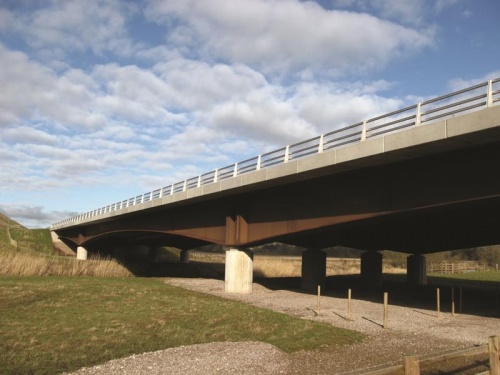
This three-span [[Multi-girder composite bridges|multi-girder steel composite bridge]] carries the A66 Temple Sowerby Bypass over the River Eden and flood plain with a main span of 64m, and side spans of 34m. [[Weathering steel]] was specified for this low-lying bridge to help it blend into the rural surroundings, and to minimise future maintenance requirements. | This three-span [[Multi-girder composite bridges|multi-girder steel composite bridge]] carries the A66 Temple Sowerby Bypass over the River Eden and flood plain with a main span of 64m, and side spans of 34m. [[Weathering steel]] was specified for this low-lying bridge to help it blend into the rural surroundings, and to minimise future maintenance requirements. | ||
Latest revision as of 12:00, 12 March 2019
This three-span multi-girder steel composite bridge carries the A66 Temple Sowerby Bypass over the River Eden and flood plain with a main span of 64m, and side spans of 34m. Weathering steel was specified for this low-lying bridge to help it blend into the rural surroundings, and to minimise future maintenance requirements.
The deck comprises four main girders, fabricated from S355J2W steel to EN 10025-5[1], that are haunched up to 3.3 m deep at the intermediate piers.
In total, 1351t of steelwork was erected using a TC3200 strut jib crane in autumn 2006. The west span and pier girders were assembled into ‘span and cantilever’ lengths adjacent to the site, moved up to the erection crane by SPMT (self propelled modular trailer) and then lifted into position. The 800t capacity mobile crane then moved to the east side of the bridge where the east span girders were erected onto temporary trestles. The east pier girders were then lifted into position to form ‘span and cantilever’ lengths. Finally, the 36m long central span girders, each weighing 62t, were lowered into position at a lift radius of 58m
| Structural engineer | Scott Wilson |
| Steelwork contractor | Mabey Bridge Ltd. |
| Main contractor | Skanska Construction (UK) Ltd. |
| Client | Highways Agency |
References
- ↑ BS EN 10025-5: 2004, Hot rolled products of structural steels, Part 5: Technical delivery conditions for structural steels with improved atmospheric corrosion resistance, BSI


