


Riverside Development, Craven Cottage, Fulham FC
Article in NSC February 2021

Stand up for Fulham
One of London’s most famous football grounds is undergoing a significant redevelopment with the construction of a new Riverside Stand.
Situated on the banks of the River Thames, Fulham FC have played at Craven Cottage since 1896, making it one of the oldest continuously used stadiums in English football. Renowned for its intimate atmosphere, as the fans are close to the pitch, the stadium has seen a number of changes over the years. Of particular note was the opening in 1905 of the first stand designed by the celebrated stadium architect Archibald Leitch, which is still in use today as the Johnny Haynes Stand. Mr Leitch also designed the famous Cottage, a corner pavilion that was common at Scottish football grounds, and is one of the last remaining examples in English football. The other sides of the ground have all seen changes over the years, most notably the construction of seated stands that replaced the standing terraces behind both goals.
Currently, the club is redeveloping the side of the ground opposite its famous Johnny Haynes Stand, the Riverside Stand, which as the name suggests backs on to the adjacent River Thames. A new two-tiered stand will accommodate restaurants overlooking the river, events spaces, a health club complete with roof-top pool, a boutique hotel and a roof terrace. It will of course address the Club’s operational and sporting requirements during the football season, but importantly also provide a new destination for local residents and visitors to the area on non-match days, providing new revenue streams for the client and reaffirming the stadium’s position at the heart of the community.
Designed by architect Populous and engineered by WSP, the development is not just a sports structure, it also includes a transformation of the riverside walkway into a world class leisure destination; a pathway that will allow an uninterrupted walk along the banks of the River Thames between Hammersmith and Putney Bridges and a choice of amenities for visitors to enjoy throughout the year.

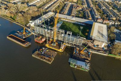
The project’s main contractor Buckingham Group started on site during the summer of 2019, with the demolition of the old stand. This was followed by an extensive groundworks programme that included the installation of a new river wall that will facilitate the pathway. A basement was excavated, work which saw approximately 45,000m3 of material leave the site by river, and then the plot was sheet piled and waterproofed.
Steelwork for the stand starts at basement level, and this area, along with a central core (there are four stability-giving steel cores in total) were the initial parts to be erected. Once this stability-giving element was completed, steelwork contractor Severfield worked outwards in two directions from this central point to erect the majority of the structure. According to Buckingham Group Project Manager Andrew Mackintosh, the reason for using this sequence of steel erection was because the central core risers provide a main distribution route to/from the plant deck enclosed within the roof envelope and getting this erected early has allowed the installation of this important equipment to commence early.
Overall, the steel-framed Riverside Stand is 113m-long x 30m-wide and 30m-high. It contains six internal levels, including the basement, and the steel design is mostly based around a regular 7.4m x 9m column grid. However, the extremely tight constraints imposed by the river and the field of play has meant that irregular column layouts have invariably been required to maximise the space within the building, which is also planned around hospitality, health club and hotel uses. Consequently, at either end of the stand the column spacings take on a far more irregular configuration as this part of the structure accommodates the hotel, swimming pool, gym and conference rooms. Like many stadiums, the tiers are formed with steel rakers that support precast terracing units.
WSP Associate Director Andy Heffer says a number of material options were initially investigated for the scheme, but steel is the traditional choice for large cantilever roof structures, which the stand has, while steelwork was chosen for the main structure and tiers because of the unique logistical constraints of the site. “In order to improve the programme many previously concrete designed elements, such as the cores, were changed to steel and this has allowed the project to be constructed in a partly top-down sequence with steel columns springing directly from basement pile caps. This then allowed the steel frame to get underway with the concrete basement slab and buried drainage works undertaken after the frame was erected.”
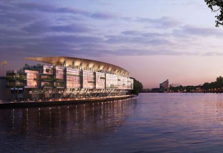
Visualisation of the completed Riverside Stand
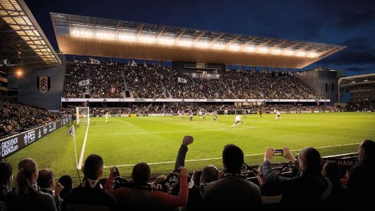
The new stand will enhance supporters’ match day experience with a host of facilities


The form of the building is said to have been designed to echo the gentle curve of the river. Its glass façade will allow natural light into the interiors, providing stunning views from every level, while the roof structure is supported by steelwork to create the striking visual effect of the roof floating in the air, high above the seating tier.
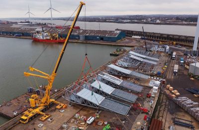
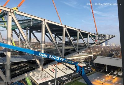
The construction of the Riverside Stand’s roof involves the installation of a series of 35m-long steel trusses, which taper down from a maximum depth of 5m (see below). Because the site is extremely confined with little or no room for materials to be stored, the trusses have been assembled at a satellite site in Tilbury Docks. “The roof trusses were assembled at the Docks into seven pairs that included all secondary steelwork. They were also fire protected and partially clad, before being floated upriver by barge,” explains Severfield Senior Project Manager Gary Dooley.
The journey upriver from Tilbury to Fulham had to be meticulously planned and arranged around low tide. The River Thames, all the way up to Fulham and beyond, is subject to tidal movements and during high tide the trusses would have been too high to navigate under some of the river’s bridges. Once the trusses had arrived at the construction site, they were lifted into place using a 400t-capacity crane positioned on a jack-up barge moored in the river. Each pair of trusses weighed approximately 50t and the gaps between each pair were infilled as the erection sequence progressed.
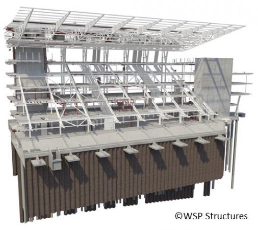
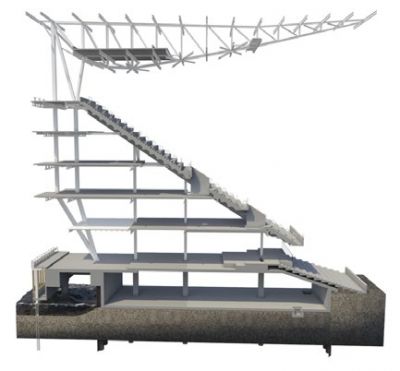
Model showing the steel frame of the new stand and its roof
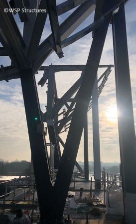
Feature columns adorn the river side of the new structure


In order to achieve the project’s elegantly designed roof, there are supporting columns setback at each end. To cover the extreme ends of the seating, additional gable trusses, which cantilever 4m beyond the final main truss have been added. These were lifted into place attached to a pair of trusses, creating two slightly heavier pre-assembled triple elements.
In conclusion, Mr Mackintosh says: “During this difficult time, our project team has successfully and rapidly adapted to new remote working practices for design coordination and collaboration in order to keep this scheme on schedule. Buckingham Group, alongside WSP and Severfield have made use of model sharing, via MS Teams, Navisworks and other online services, highlighting how everyone has embraced the new working ‘normal’.”
Roof stability

The roof structure is formed by 16 main cantilever trusses that feature tapered plate girders towards the front edge. Out-of-plane forces acting longitudinally along the roof are resisted through bending in each of the triangulated roof column sets that cantilever from the superstructure below and support the root of the trusses.
Having no lateral cross-bracing was a key architectural driver. So, the in-plane overturning effect from the cantilever roof as well as transverse wind loads are resolved through axial loads in the same column sets that are propped at level five by the raking beams that support the seating tier.
A portion of the overturning moment is also resisted by columns forming a Vierendeel frame that runs from the top of the roof down to ground floor. Horizontal components of the axial forces within the raker beams are brought into the floor diaphragms through tie beams at each level with vertical loads taken through the building columns.
Much of the overturning moment is reduced at level two where the Vierendeel frame forms a knee joint before combining into a V-column arrangement at ground level. This feature, which developed from a desire to keep intrusion on the river walk to minimum, serves to reduce the lateral forces by using the buildings own dead weight to counteract the overturning moment in the roof.
Fulham Stadium

The vertical Vierendeel trusses help to manage the overturning from the cantilevering roof trusses. Richard Henderson of the SCI discusses some features of the behaviour.
Vertical Loads
Between the stability cores, the cantilevering roof trusses apply a bending moment to the top of the vertical Vierendeel trusses spanning between levels 2 and 5. Arranged in storey-height rectangular panels, the spaces along the façade are uninterrupted by bracing. A more usual arrangement of a vertical cantilever truss, used for stability bracing for example, would involve the columns continuing to the ground with a tension and compression applied to the foundations when resisting overturning. In this case, at level 2, the columns rake under the cantilever roof and come together at a common node closer to the line of action of the roof load, thus increasing the reaction at this point. The floor loads applied to the Vierendeel columns provide a restoring moment.
The inclined beam supporting the seats props the Vierendeel truss at level 5. The horizontal prop force in the inclined beam is carried in shear by the vertical truss and is resolved at level 1. This simplified description of the behaviour ignores any effect of propping from the intermediate floors, the magnitude of which is determined by the relative in-plane stiffness of the diaphragms and the bending stiffness of the truss.
Lateral Loads
The prevailing south westerly wind loads on the stand add to the overturning effect of the roof trusses. When the wind is north-easterly, the overturning from the weight of the roof is countered as the wind will tend to apply an uplift to the projecting structure. The horizontal loads due to wind are transferred through the floors by diaphragm action to the stability cores and do not add to the shear force carried by the Vierendeel trusses.
Effect of Vierendeel Action
The absence of diagonal bracing in the vertical trusses means that half the prop force is carried in each column in shear. At the floor levels, the column to beam joints are rigid and carry a significant bending moment as well as the axial load. The effect of the combined bending and axial load means the column elements are substantial. The magnitude of the prop force and therefore the column bending moment can be controlled by adjusting the rake of the columns from level 2 to the common node at the ground floor.
| Architect | Populous |
| Structural Engineer | WSP |
| Steelwork Contractor | Severfield |
| Main Contractor | Buckingham Group |
| Main Client | Fulham FC |