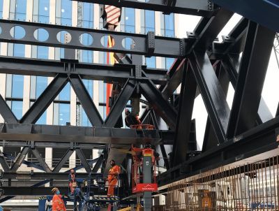
One Centenary Way, Birmingham
Article in NSC September 2021
Second city paradise
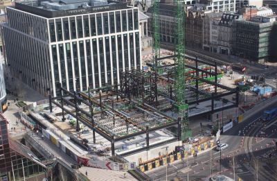
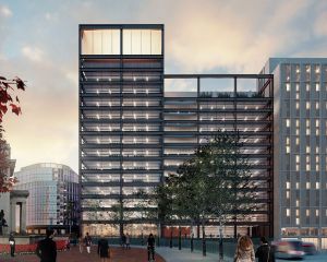
Spanning the A38 dual carriageway, the steel-framed 13-storey One Centenary Way is the first building to be constructed in phase two of Birmingham’s Paradise development.
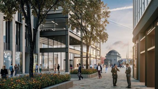
A new mixed-use scheme is taking shape in the centre of Birmingham, changing an historic area of England’s second city into a new vibrant business and leisure destination. Formerly known as Paradise Circus, and now renamed simply as Paradise, the redevelopment is being constructed in three phases, with the initial phase including the completion of two office blocks known as One and Two Chamberlain Square. Phase two is now underway, and this involves the construction of One Centenary Way, a 13-storey commercial building.
Containing more than 7,000t of structural steelwork, the project will on completion be a stand-out building featuring an exoskeleton on all four elevations. The expressed and exposed nature of the steel frame also extends to the interior of the building, where columns, beams and connections will also be on display. Below ground level, the steelwork is no less impressive as just over 60% of the total footprint of the building is sat on top of a series of trusses that span the A38 dual carriageway tunnel, a key transport artery through the city. In addition, the site overlays a major services tunnel. This, along with the proximity of the adjacent above ground highway results in an unusually challenging site for a development in Birmingham.
“One Centenary Way is an important building for the Paradise masterplan as it will be the first building of Phase Two to complete. It will also be an important building for Birmingham, not least for its green credentials, but it will be the first commercial exoskeleton building in the region,” says Glenn Howells Architects Partner Dav Bansal.
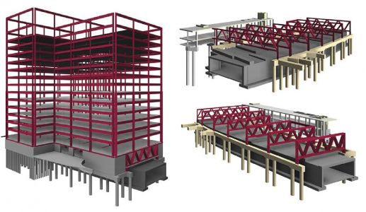
Approximately 1,950t of structural steelwork has been used to fabricate the 16 storey-high trusses, which are up to 34.6m-long and weigh up 130t. Fabricated at BHC’s Lanarkshire facility, the trusses were transported to site as complete sections, measuring up to 6m-wide. Once on site, a 1,200t-capacity mobile crane, one of the largest in the UK, erected each of the trusses.
According to Ramboll Principal Engineer Daniel Yoxall, the trusses are said to be among the largest ever designed and constructed in the UK for a commercial building. “Although the trusses were delivered and lifted into place as individual items, 14 of them are installed as pairs, tied together in-situ with cross members, as this configuration was better suited to transferring the loads from the building above to the foundations below. The exceptions are two single trusses at either end.”
The steel frame sits on top of a series of trusses that span a major thoroughfare
The trusses form part of the basement level and their top chords help form a platform to support the majority of the building’s structural frame. One of the building’s two basement levels is accommodated within the trusses’ depth. This upper basement floor will house a well-equipped and accessible cycle hub for the whole estate. With just over 300 spaces, this will be Birmingham’s first city centre major cycle hub offering associated facilities including showers and locker rooms together with servicing and bike hire. The part of this floor level that is not within the trusses will accommodate a retail basement area and vehicular ramps for the car parking that is also located in the basement.
Approximately two-thirds of the project’s steel frame is supported by the truss steelwork. The steel frame structure is fundamental to realising the development potential of the site and is architecturally celebrated in the form of Vierendeel exoskeleton frames, which provide lateral and vertical support to the building. “Due to the tight site constraints, we couldn’t have a typical load-bearing core with columns going into the ground to hold the building up and give it stability. The solution, therefore, was using the building’s façade to provide the stability in the form of a Vierendeel exoskeleton,” says Mr Bansal.
As well as the stability provided by the exoskeleton, there is also a centrally-positioned steel braced core that provides some stability. “The exoskeleton on its own doesn’t provide enough stiffness for the overall structure, so the two stability systems work in tandem,” explains Mr Yoxall. The project is using a steel core, instead of a concrete one as the former offers a lighter solution. This was important, as the core had to be positioned on top of the trusses, so it could sit in a central position within the building and thereby satisfy the desired internal office layout.
The Vierendeel exoskeleton is formed with a series of vertical and horizontal steel sections forming 12m-wide rectangular boxes. The rectangles incorporate 3m-wide horizontal windows, encased within an exposed structural steel façade. The innovative, structural-led design is said to be a response to the complex site location. The interior of the building will offer large office floorplates of up to 2,090m2, as well as retail space at ground floor level. The column grid is based around a 12m × 9m spacing, as this layout requires minimal internal columns, while also providing the desired modern open-plan office layout.
Cellular beams have been used throughout to accommodate the building services within their depth. They support metal decking, which along with a concrete topping forms a composite flooring solution for every level above the ground floor slab.
As well as retail, the ground floor also has a triple-height reception area with a floor-to-ceiling height exceeding 9.5m. To accommodate this much higher and impressive reception area, the first floor does not cover the entire building footprint. The upper floors have a standard 3.8m floor-to-ceiling height.
Summing up, MEPC Regional Development Director Rob Groves says: “One Centenary Way is a truly exemplary building that I am convinced will become one of the city’s major landmarks. There’s nothing else quite like it in terms of design and it will not only mark out Paradise, but also this whole area of the city centre. With the delivery of the trusses, we see the practical application of one part of our vision not just for this building, but the whole scheme.”
Complex Foundation Solutions
Ramboll designed the complex piled substructures for the building to transfer the structural loads safely into the ground while avoiding any overloading of the tunnels. Sophisticated geotechnical modelling was utilised to demonstrate to the asset owners that the new development would not negatively influence the existing tunnel structures, as required by the rigorous approvals process. Ramboll’s survey team produced a 3D laser scan of the tunnels to allow their positions to be accurately recorded and provide a full 3-D photographic record of their condition. Continuous tunnel monitoring throughout the works ensures that tunnel movements are always within acceptable limits.
Truss design
Trusses are a key part of the One Centenary Way structure – Vierendeel trusses for the exposed exoskeleton and Warren trusses supporting the superstructure. David Brown of the SCI comments on truss design.
Truss design appears to be one of the simpler design activities in steel structures – determine the loads, determine the geometry and analyse the truss to calculate the member forces. For a Warren truss, the initial analysis would probably assume pinned joints, so even manual analysis is easy, by resolving at joints or taking moments at selected cross sections. Although simple analysis of a Vierendeel truss is possible, the moment resisting joints mean a computer analysis is the realistic option.
Whichever route is taken, the initial sizing of the truss members is usually straightforward. At this point, the hard work begins, as the joint design – an essential part of truss design – is much more involved. As can be seen in the images of the Warren trusses at One Centenary Way, the truss nodes are three dimensional, complicated details with a physical size that does not match the analysis assumption of a node in an analysis model.
The usual approach with Universal Column (UC) profiles is to assume the axial force in a member is distributed within the cross section in proportion to the area of the element, so each flange is typically allocated 40% of the axial force. The load paths of each part of the member force can then be considered, verifying if the element within the node can accommodate the design forces. With open sections such as UCs, it might be anticipated that the chord flanges would need stiffening (to ensure the welded connection is fully effective) and that the chord web may need reinforcement over the length of the node. The main members are usually highly stressed before the additional local stresses are considered.
Practical issues of node geometry are important at this stage – can the welds within the node actually be completed? Are member elements overlapping so much that access is impossible? Best practice in truss design is certainly to consider the joints at the design stage, adjusting the member sizes and geometry (which may affect the truss analysis) to ensure a reasonable solution can be achieved. Careful consideration of the necessary site splices is also critical, since large forces mean many bolts, many bolt holes and significant loss of the cross-sectional area. The net area checks may become critical in these details.
| Architect | Glenn Howells Architects |
| Structural Engineer | Ramboll |
| Steelwork Contractor | BHC |
| Main Contractor | Sir Robert McAlpine |
| Main Client | MEPC |


