


100 Bishopsgate, London
Article in NSC January 2018

Shape shifter
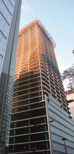
Transforming from a parallelogram at its base to a rectangle at the top, the 40-storey 100 Bishopsgate project is the City of London’s latest stand-out commercial development.
By Martin Cooper
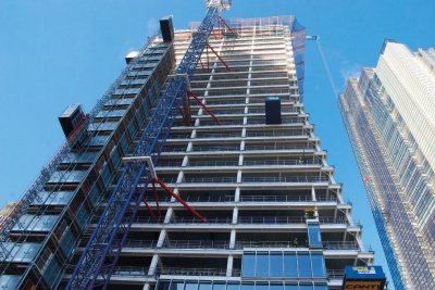
The steelwork for 100 Bishopsgate has recently been completed, topping out the frame for the City of London’s latest addition to its ever-changing high-rise cityscape.
This 40-storey mixed-use commercial development, situated a stone’s throw from Liverpool Street Station, will provide just over 83,900m2 of net lettable space within its main tower and a contiguous six-storey podium. The 60m-long podium, adjoining the main tower along its eastern elevation, accommodates large column-free floors in excess of 4,080m2. The podium will be topped by a landscaped roof terrace, offering tenants on that floor a large outdoor breakout or entertaining space.
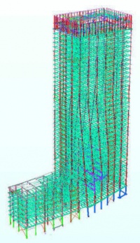
Perimeter steelwork for the scheme starts at ground floor and the frame is sat atop a three-level concrete basement. In addition, there are steel plunge columns temporarily supporting the core extending down within the permanent piles. Forming this basement was the first part of the construction programme to be undertaken when work kicked off in 2015. The upper level of the basement was excavated and the ground floor cast. The use of plunge columns then allowed the basement to be constructed top-down simultaneously with the concrete core construction and steel frame erection starting above.
Alongside the development, a new half-acre public realm boasting restaurant and retail amenities will provide pedestrian access between Bishopsgate, St Mary Axe and Camomile Street to the north. Forming another part of the overall scheme, 15-16 St Helen’s Place is separated from the main structure by this realm. The six-storey steel-framed St Helen’s Place structure incorporates a retained façade and shares a basement with 100 Bishopsgate.
The main 40-storey tower provides the main stand-out element of the project. With floorplates ranging from 1,800m2 to 2,300m2, the space is said to be suitable for a range of City tenants and, unsurprisingly, large parts of the building have already been let. In fact, the scheme is 68% let to various tenants including Royal Bank of Canada, Jefferies, Freshfields and Equinox.

According to architect Allies and Morrison, the form of the tower responds to the geometries of the site and context by transitioning from a parallelogram at its base to a rectangle at its top. In combination with contrasting façade textures and articulated junctions repeated rotationally around the building, this transition in form lends the tower a distinctive twisting dynamic.
To form this eye-catching shape, two façades, north and south, feature a series of inclined columns. They are installed in a staggered configuration from ground level up to level 24, where the entire building straightens into a rectangle. The sloping elevations have a fold that stretches upwards from east to west on the north side, with the geometry then reversed on the south façade. The folds end a bay in from the building’s perimeter at one end, meaning the eastern end of the north elevation slopes and the western end has straight columns. Again, this twisting geometry is reversed on the south side.
In the areas where the folds straighten, raking columns change position, and consequently large axial loads are encountered. “Large tension and compression forces are transferred to the core in these areas, and in order to help distribute these loads we have two storeys with extra bracing in the floors,” explains Robert Bird Group Director Russell Whitehead.

Based around a centrally-positioned core, steelwork radiates outwards to supporting perimeter columns spaced at 9m centres. Accommodating the building’s services within the structural ceiling void, 700mm-deep Fabsec cellular beams have been used throughout the scheme. Because of the tower’s changing sloping shape the internal spans along the north and south elevations vary from a maximum of 23m-long to 11m-long on level 24. As the building turns into a rectangle, the levels from floor 24 upwards all have 11m internal spans. Except for the declining length of the internal beams, the steel frame is fairly repetitive until the uppermost plant level at floors 38 and 39. Here three 4.5m-deep trusses, each 22m-long, have been installed to support plant equipment.
Steelwork contractor William Hare’s package consists of a grand total of 15,000t of steel, which includes more than 6,500 individual pieces. The company, alongside Structural Metal Decks (SMD), is also installing 90,000m2 of metal decking for the project’s composite floor construction.
In recognition of its good working practice Multiplex won a Silver Considerate Constructors Scheme 2016 National Site Award. In addition the Project was awarded the City of London Corporation’s Chairman’s Cup for most Considerate Contractor in the City of London. The 100 Bishopsgate job was said to have shown the highest levels of consideration towards the public, its workforce and the environment through adhering to the Scheme’s five-point Code of Considerate Practice.
100 Bishopsgate is due to complete in early 2019.
Blast resistant design
Once the scheme began construction in 2015, a design change relating to the structure’s blast resistance was undertaken. “Initially the main tower was to feature a truss that wrapped around the structure at level six,” says Multiplex Construction Director Cliff Wynn. “This would have helped to support the building in the event of a blast.” However, a more cost-effective cutting edge engineering solution was devised, taking away the need for extensive welding at level six.
During the construction programme for the ground floor, a two-stage procedure was employed with the main steel columns being installed first. CHS shrouds were then slipped over the columns and grouted into place. These 9m-high columns weigh up to 30t with their shrouds and base plates.
Inclined columns
Richard Henderson of the SCI discusses some of the structural consequences of inclined columns.
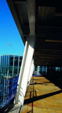

The crisply folded surfaces of the sculpted façade of 100 Bishopsgate indicate the changes in slope of the column centrelines behind. The columns are vertical through the upper storeys and become inclined outward below the horizontal fold lines. At the change in direction of a column, the horizontal component of the outward-sloping lower portion is resisted by a compression in the floor structure. At various heights lower down the building, the inclined columns become vertical again with the horizontal component this time resisted by a tension in the floor structure.
The horizontal components at the changes in direction are large: for example where a column which carries about 50 m2 at each of 17 storeys changes from vertical to a slope of 1 in 8, it is likely to have a horizontal component of the order of 1 MN. Where a floor beam is carried by an outwardly inclined column and the slope continues past the floor, a smaller horizontal compression is developed in the floor structure. If all the horizontal components (both tension and compression), are resisted by the core the net horizontal load is zero.
The folds are present in the north and south elevations so where the horizontal thrusts are equal on both sides, they can be passed through the core without resulting in a shear force in the vertical walls. Where the geometry is such that the thrusts from the two sides are different, the core walls are subjected to shear and bending due to the net horizontal components of the vertical loads. These actions are present in the core walls until the balancing tension cancels them out.
The building’s core layout shows the perimeter columns are in line with vertical walls which are therefore available to resist these forces, except for the middle column on the longer façades. At this position, any out of balance in the horizontal components of the column loads in the floor structure needs to transfer sideways to the vertical structure.
The steel floor structure is connected to the concrete core using cast-in plates. The floor plans suggest the floors are present right up to the core walls and if so, the horizontal components of the column forces can be transferred to the cores through the concrete floor slabs. This would allow the connections to the floor beams to be designed as simple connections (carrying vertical load only) in accordance with the SCI “Green Book”.
| Architects | Allies and Morrison, Arney Fender Katsalidis |
| Structural Engineer | Robert Bird Group |
| Steelwork Contractor | William Hare |
| Main Contractor | Multiplex Construction Europe |
| Main Client | Brookfield Properties |