


Facades and interfaces
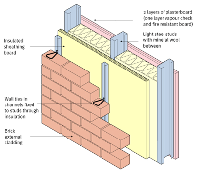
Façade systems comprise the structural elements that provide lateral and vertical resistance to wind and other actions, and the building envelope elements that provide the weather resistance and thermal, acoustic and fire resisting properties. The types of façade system that are used depends on the type and scale of the building and on local planning requirements that may affect the building’s appearance in relation to its neighbours. For example, brickwork is often specified as the external façade material, but the modern way of constructing the inner leaf consists of light steel wall elements (called infill walling) that have effectively replaced more traditional blockwork.
Other types of façade materials may be attached to light steel walling, such as insulated render, large boards, metallic panels and terracotta tiles. A wide variety of facade treatments and shapes may be created using light steel wall including large ribbon windows, curved and inclined walls, and with projections such as solar shading or balconies. Façade materials may be mixed to enhance the aesthetics of the building. It is also possible to pre-fabricate light steel wall panels with their cladding pre-attached.
In multi-storey buildings, unitised curtain walling systems have been developed that are attached to the floors or edge beams of the primary steel structure. Steel and glass are also widely used in façade and roofing systems, and the local attachments are in the form of stainless steel brackets.
Other interfaces that affect the design of the façade include the attachment of brickwork to steel edge beams, the design of projecting balconies, solar shading and attachments of parapets.
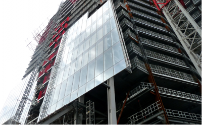
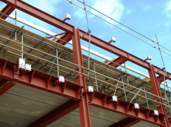
Installation of a unitised curtain walling system
(Image courtesy of Arup Facades)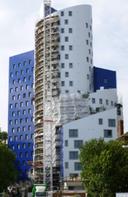
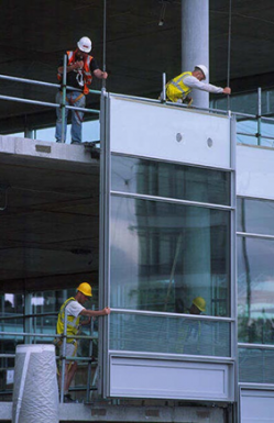
Installation of lightweight facade system attached to a modular building through a mast climbing system.
(Image courtesy of Futureform)


[top]Façade functions
The building façade provides the separation between the inside and the outside environments but is also required to provide acceptable light levels and a visual connection with the outside in the form of views out of the building. The façade may also be required to provide the building user with openable windows for ventilation.
The separating functions include:
- Weather tightness including elimination of water ingress and control of air permeability and resistance to wind actions;
- Insulation (both thermal and acoustic);
- Control of solar gain and ultraviolet radiation and the management of views into the building.
The building façade also provides the owner and the architect with a canvas on which to create an image representing the owner’s business, ideals or outlook.
[top]Elimination of water ingress
A fundamental requirement of a cladding system is that water does not leak through it into the building. One means of eliminating leaks is to create a face-sealed system over the whole building, equivalent to a weatherproof membrane. Once such a system is perforated, water leaking through the perforations is inside the building. In practice, it is difficult to achieve such a face-sealed system because of the complexity of the interfaces between the various materials and components in a building envelope and its exposure to weathering.
A more reliable way of providing resistance to water ingress is to adopt a system with primary and secondary defences. The primary defence is intended to resist most of the incident rain but if water leaks past the primary (outer) defence, the secondary defence intercepts the water and directs it to the outside. Rain screen systems and glazing and framing profiles are designed in this way.
The level of exposure of buildings to the weather is related to the design wind pressure. The level of performance of a building envelope can be specified and resistance to water penetration tested. The Centre for Window and Cladding Technology (CWCT) publishes a ‘Standard for systemised building envelopes’[1], which sets out performance categories and corresponding weather tests related to the design wind pressure.
[top]Control of air permeability

(Image courtesy of BSRIA)
Air permeability is controlled in the design and construction of building envelopes to manage the rate of heat loss or gain due to the exchange of air with the outside, to assist in reducing carbon dioxide emissions. Standards of air permeability are identified in the Air Tightness Testing and Measurement Association (ATTMA) guide and specification for air permeability[2].
| Building type | air permeability m3/(hr.m2) at 50 Pa | |
|---|---|---|
| Best practice | Normal | |
| Offices: | ||
| *Naturally ventilated | 3.0 | 7.0 |
| *Mixed mode | 2.5 | 5.0 |
| *Air conditioned/low energy | 2.0 | 5.0 |
| Factories/warehouses | 2.0 | 6.0 |
| Superstores | 1.0 | 5.0 |
| Schools | 3.0 | 9.0 |
| Hospitals | 5.0 | 9.0 |
Pressure testing is required under the Building Regulations which state that all buildings that are not dwellings must be subject to pressure testing (subject to some exceptions).
Compliance is demonstrated if the measured air permeability is not worse than the limiting value of 10 m3/(hr.m2) at 50 Pa and the building emission rate (BER) calculated using the measured air permeability is not worse than the target CO2 emission rate (TER). Requirements are also specified for dwellings.
[top]Resistance to wind actions

Mullions and transoms
Building cladding systems are required to sustain wind actions and transfer them to the main building structure. Systems are usually mounted on a building floor by floor so at each floor level the building frame supports the weight of one storey height of the envelope. The envelope may either be bottom-supported or suspended from the floor above. Wind actions are transferred by the cladding system to the building floors which act as a linear support. Building cladding systems formed of large panels are usually one-way spanning. Each floor level therefore supports one level of wind load on a building.
Curtain walling panels are usually two-way spanning, supported on four sides by the transoms and mullions which frame them. Transoms span side to side, supported by the mullions which span from floor to floor. Loads are transferred by brackets, usually fixed at the edge of the floor slab. The mullions are usually provided with sleeved joints to achieve transfer of shear forces at the joints. Mullions are usually top-hung so that they act in bending and tension.
Rain screen cladding, masonry and insulated render are fixed to supporting systems which are usually designed to span from floor to floor.

[top]Thermal and acoustic insulation
The building façade is required to perform a thermal insulating function which is becoming increasingly onerous under the pressure to reduce energy consumption and CO2 emissions. Insulating material is incorporated into the opaque parts of the façade and insulating glazed units (igus) are used in the transparent areas. Minimum U-values are given in the Building Regulations, equal to 0.35 W/m2K for walls and 2.2 W/m2K for windows and curtain walling. Better insulation (lower U-values) averaged over the building envelope can be achieved by increasing the areas of opaque wall and reducing the areas of windows.
The building envelope also provides acoustic separation between the external and internal environments. In general, a building envelope constructed of more massive elements (e.g. masonry or pre-cast concrete) provides better acoustic separation.
[top]Solar gain, light levels and views out

Large areas of glazing which extend from floor to ceiling in many office developments provide excellent views out of the space and good levels of natural light. Levels of natural light diminish with distance from the façade and 18m is the plan depth (facade to façade or façade to atrium) above which natural light is considered to be too low.
The penetration of direct sunlight into a building causes solar gain and glare, both of which increase with a greater expanse of glazing. These effects vary with the time of day and with the seasons and both need to be allowed for in the design of the façade. South elevations receive stronger sunlight from a higher angle and can be shaded using horizontal louvres or brises soleil. Glare from low-angle sunlight can be a particular problem in the early morning and late evening for east- and west-facing elevations. Shading can be provided with vertical fins or with user-operated blinds.
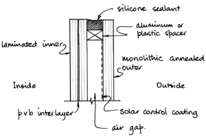
Solar gain can be reduced by specifying a selective solar control coating on one of the surfaces of the glass (usually in the cavity of an igu). The coating is called selective because solar radiation of different wavelengths is selectively allowed to pass through the coating: visible wavelengths of light are allowed to pass more freely than infrared wavelengths.
For spaces for exhibitions or displays of materials susceptible to ultraviolet (uv) degradation, a uv-inhibiting film can be applied to the surface of glazing or laminated glass can be specified with sufficient interlayers between the glass laminates to absorb uv radiation.
- Solar shading
Vertical aluminium fins
Horizontal glass louvres


Solar gain must be allowed for in the design of the building services. The benefits of full-height glazing have been questioned as a result of pressure to reduce energy costs because there is little advantage to natural light levels in having glazing below desk level but full-height glazing increases the heating and cooling demand and increases energy costs. The Target Zero Programme considers these issues in the context of different building types.
Schools, hospitals and residential buildings frequently have larger areas of solid wall and smaller windows as a proportion of the façade area and so these issues are less significant.
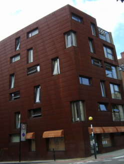
[top]Image

One of the most significant functions of a building facade is to project an image. This may be of a place, of the building owner or user, of the buildings function or of the architect.
The choice of materials, incorporation of features, expression of structure, scale, views into the building may all be used.
- Architectural features
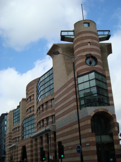
Strong referential image
Expressed structure in large partially enclosed volume


[top]Types of façade systems
A wide variety of façade systems may be used in modern multi-storey buildings, which are:
- Brickwork and stonework (masonry)
- Curtain walling
- Precast concrete panels with various types of finishes
- Insulated render
- Metallic cladding
- Tiles and stone veneer panels
- Large boards consisting of an aesthetic and weather tight veneer
- Glass and steel façade systems

The choice of facade system is dependent on the scale and use of the multi-storey building, and on its local environment and neighbours. A variety of steel components may be used in modern facade systems, such as:
- Steel profiled sheets and composite (sandwich) panels
- Flat and rigidised cassette panels with folded edges
- Light steel infill walls using C sections
- Hollow steel sections (often circular) for facades and roofs, particularly used for visual effect in atria and in entrance areas
- Stainless steel glazing support systems
- Metallic elements in unitised curtain walling
Light steel infill walls have largely replaced the block-work inner leaf in both steel and concrete framed buildings. A variety of facade systems may be attached to the infill walls. Some examples are illustrated below.

[top]Benefits of steel façade systems
The benefits of steel façade systems may be presented in terms of their functional and aesthetic requirements, as follows:
- A variety of colours and surface textures is possible
- Lightweight facades minimise the loads on the supporting structure
- Light steel infill walls using C sections can be used to support a wide range of cladding systems
- Facades can be highly pre-fabricated for speed of installation
- Steel glazing systems can be used for visual effect in tall entrance areas and atria
- Steel is non-combustible and robust to damage in façade panels
- A high level of thermal and acoustic insulation can be provided.

Use of composite (sandwich) panels to support tiles.
(Image courtesy of Kingspan Panels and Profiles)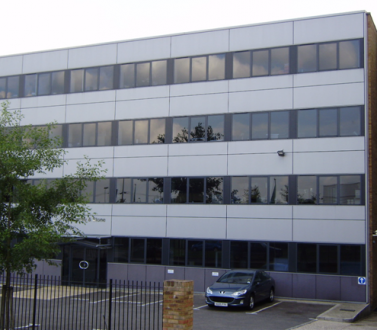
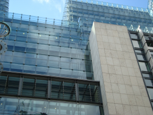
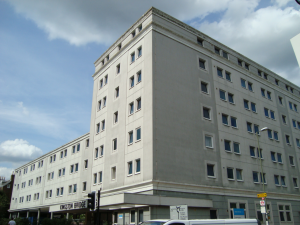
Use of large metallic panels in over-cladding of an existing office building.


[top]Solutions using light steel infill walls

Light steel walls may be of two types:
- Light steel infill walls that span between the floors or between the floor and edge beam
- Panelised systems that are placed outside the slab edge and are attached at discrete locations.
Light steel infill walls are more widely used because of the simplicity of the installation process and the ability to deliver cut-to-length C sections for the particular as-built dimensions of the project.
The development of light steel infill walls has been one of the major innovations in the last 10 years. Light steel infill walls consists of C sections that span 2.4 to 5m between floors, and are designed to resist the wind pressures applied to the building façade and also to support the weight of the particular type of cladding system that is attached to them.
[top]Benefits of light steel infill walls
The benefits of light steel infill walls are:
- Rapid construction system with an installation rate of over 50m2; per day
- Less materials handling on site than for brick and block-work
- Tall walls up to 5m and high wind pressures up to 2kN/m2;
- Ability to create large windows without wind posts
- Minimum material use (less than 5kg/m2; of steel in the façade)
- No on–site waste when C sections are delivered cut to length
- Light weight, which reduces the loads on the supporting structure
- Can be used for a wide range of cladding systems
- Can be dismantled in building extensions etc. and re-used
[top]Design of infill walls
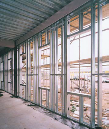

(Image courtesy of Metsec)
The design of light steel infill walls is dependent on the wall height and wind pressures acting on the façade. Normally the C sections are 100 to 150mm deep with steel thicknesses of 1.2 to 1.6mm. The C sections are placed at 400 or 600mm centres, which is compatible with the attachments to the internal plasterboard and external cladding.
Large openings can be created by placing pairs of C sections vertically next to the openings, and sometimes pairs of C sections above and below the openings. The steel thickness can also be varied across the façade without changing the section size. For example, wind pressures are higher at the corners of the buildings and also increase with height. The deflection limits that are specified in design depend on the types of cladding that is attached.
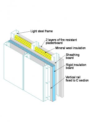
[top]Thermal performance
Thermal insulation is attached externally to the wall and mineral wool is often placed between the C sections to achieve the required thermal insulation (U-value). For insulated render or rain screen cladding systems, an external sheathing board is often used to provide local support to the external cladding.
A U-value of 0.15 W/m2;K can be achieved by approximately 100mm of closed cell insulation board fixed to the C sections or sheathing board supplemented by 100mm of mineral wool between the Cs. The same wall build-up may be used for all types of cladding systems.
Air-tightness is also important in modern building design, and it can be improved by use of a sheathing board fixed to the C sections.
[top]Construction process
Light steel infill walls are generally installed as individual C sections that are cut to length and are placed between the floors or edge beams. The C sections are attached to a U shaped bottom track which is attached to the floor slab. At the top of the wall, the C sections slide in a U shaped top track that is fixed to the underside of the edge beam or floor slab permits relative movement without compressing the wall. The general guidance is to provide a minimum of 20mm relative movement in a concrete framed building and 10mm in a steel framed building.
Pairs of C sections are often placed either side of window or door openings to resist the loads transferred across the window. The U tracks are connected to the concrete floor slab using powder actuated pins.
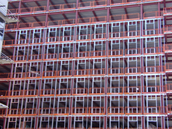
The construction process is very rapid and does not require external scaffolding until the façade is attached externally. Alternatively, the walls may be prefabricated and installed as large panels, often with the cladding pre-attached - see photograph below. In this case, the cladding panel is placed outside the edge of the primary structure, and supports the cladding fascia. The cladding around the edges of the panel is then attached on-site.
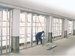
Installing light steel infill walls.
(Image courtesy of Metsec)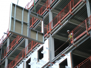
Lightweight prefabricated panel attached to a steel framed building
(Image courtesy of Kingspan Panels and profiles)


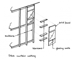
[top]Curtain walling

Curtain walling is the generic name given to metallic lightweight cladding or glazed cladding systems that are directly supported by a structural frame. In some cases, a stone veneer or large tiled fascia may be attached to give the appearance of a more monolithic cladding system.
Curtain wall systems are an assembly of factory-made components which are either made up into panels in the factory and the interlocking units brought to site and installed (unitized curtain walling) or brought to site as components and assembled on the building (stick curtain walling). Stick curtain walling is more often used on low-rise buildings and in relatively small areas because external access is required to the building elevations, e.g. from scaffolding or wall-climbing work platforms. Unitised curtain walling can be designed to be installed without using the main crane and this method is favoured on high-rise buildings. Methods used are a mini-crane mounted on the office floor or a hoist mounted on a temporary rail round the perimeter of the building.

(Image ©Tractel (UK) Ltd )
The size of the unitised panels is dictated by the floor to floor height and a sensible width for transportation and installation and should be compatible with the planning dimensions of the façade (normally a multiple of 300mm). Panels up to 1.5m wide and 4.2m high are typical. There are relatively few suppliers of unitised curtain walling systems in Europe and most have dedicated design teams who can provide detailed design and detailing for particular projects.

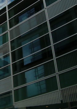
The curtain walling system is designed to provide the necessary functions of weather-tightness, natural lighting and shading, and thermal insulation. The joints between the elements of the curtain walling are therefore very important to these functions. In unitised systems, the panels are manufactured so that they are highly sealed and insulated, and the joints between the large panels are made by rubber gaskets and silicone sealants (see below).
Alternatively, the fascia may be designed to act as a rain screen by creating a cavity behind the fascia material and providing wider joints around the perimeter of the cladding panels. Therefore, under the wind action, pressure equalisation occurs between the cavity and external air so that wind driven rain is not forced into the cavity, thereby reducing the risk of water ingress through the joints.
Generally windows are sealed in modern offices and therefore control of ventilation by other means is important. A high level of acoustic attenuation can be achieved which is important in city centre buildings.
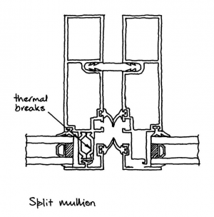
[top]Panel framing

Panels are framed by mullions on the vertical edges and transoms on the horizontal edges. Mullions and transoms are thermally broken to prevent cold bridging through the element so that condensation does not occur. Unitized curtain walling is identifiable by the presence of split mullions and transoms on the panel perimeters. The glazing units are supported on a setting block from the transom below and may either be bonded in factory-controlled conditions to the framing transoms and mullions using structural silicone or secured with a compression gasket.
By contrast, in stick curtain walling, the mullions and transoms are all individual elements. Intermediate transoms may divide the panel vertically. Insulated glazed units and solid insulated panels fill the openings framed by the mullions and transoms. The igus are supported on plastic setting blocks from the transom below and secured on all four edges with pressure plates screwed to the mullions and transoms and concealed by a capping plate.
Aluminium is easy to extrude so the framing elements which include stiffening nibs, screw races and pockets to receive gaskets are usually made from this material. These structural shapes are cheap to manufacture in large quantities once a die has been made.

[top]Weather tightness
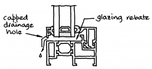

Weather tightness of curtain walling is achieved by mounting impermeable insulating glazing units and infill panels in gasketted rebates. Any water which passes the gasket into the glazing rebate is either drained to the outside through openings in the transom or directed to the mullions which form vertical drainage paths and direct water to the outside at the mullion joints.
Split mullions and transoms in unitized curtain walling include cavities with linear gaskets such as blade or bubble gaskets forming the first barrier. Any water passing the first line of defence is able to drain freely to the outside. Weather tightness is demonstrated following design by appropriate testing.
- Gaskets
Bubble gaskets
Blade gaskets


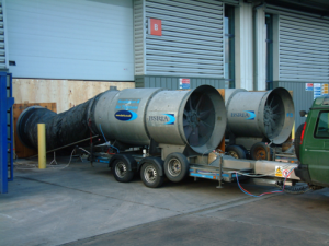
The Centre for Window and Cladding Technology (CWCT) provides technical guidance on achieving weather tightness which includes a specification for weather testing windows and curtain walling[1]. The most comprehensive form of testing involves mounting a prototype panel in a pressure box to allow the development of positive and negative pressure across the panel. Wind actions can be simulated to test panel strength and stiffness. Weather testing includes spraying water in controlled quantities and distribution under conditions of static pressure difference. Weather tightness under dynamic pressure can also be developed using an aero engine-driven propeller mounted on a frame, if required. No water ingress results in a pass of the weather test. Hose testing can also be used on specific joints.
Large areas of glazing and aluminium framing (despite being thermally broken) limit the U-values, which can be achieved with curtain walling. U-values averaged over a whole curtain wall panel are typically in the region of 1.3 to 1.7 W/m2K. The thermal performance of igus is improved by using argon (or other inert gas) filling and/or triple-glazing.
Solar gain, light levels and views out are controlled as described above.
[top]Support conditions
Curtain walling systems are generally top-hung and laterally supported at floor levels. The effects of edge beam deflections are seen in relative vertical movement between the panels supported at a given floor level and the panels supported at the floor above. For this reason, the edge beams should be sufficiently stiff to prevent any damage to the cladding system, particularly if it is highly glazed.
The span of a steel edge beam is typically 5 to 8m (6m and 7.5m are common dimensions), and the span of a concrete edge beam or slab is typically 5 to 6m. A total deflection limit of span/500 under imposed loading is normally specified for the edge beams for more brittle cladding systems. The installation of the panels should also allow for dimensional tolerances at the slab edge by use of packers or levelling devices.
Some curtain walling systems are designed with steel ’strong backs’ so that they can span directly between the perimeter columns and therefore do not require vertical support from the slab edge although they may require lateral support to resist wind action on the panel. The ability to transport and lift these large panels is the critical design consideration.
Strongback cladding system
[top]Support to brickwork

Brickwork can be attached to a steel framed building by several methods:
- It can be supported on the ground or an intermediate structure and laterally supported by the steel framework and infill wall. This approach is permitted for walls up to about 3 storeys high
- It is supported every floor or in some cases, alternate floors by stainless steel support angles that are attached to the edge beams of the primary steel structure or to the edge of the floor slab.
- Brick tiles or brick slips have also been developed which give an external appearance of brickwork but which are bonded to a sheathing board or supported on horizontal rails or sheeting.
- Alternatively, masonry facades can be formed by supporting brick or natural “hand-set” stone panels from storey-height precast concrete panels.
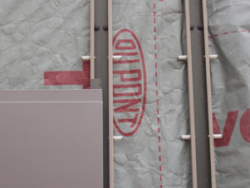
A method of fixing brickwork to steel frames
[top]Stainless steel support systems
Stainless steel support angles may be used to support brickwork at floor levels. The key design parameters are the wall height and the eccentricity of the brickwork from the supporting structure. The Stainless steel angles are typically 10mm thick so that they can be placed in the horizontal brick courses, and their position is adjustable to allow for geometric deviations in level of the coursing by attachment to stainless steel support brackets.
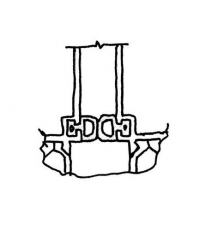
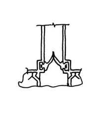
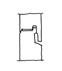
Two generic support systems for the stainless steel brackets may be used:
- Connection to the steel edge beams, which are generally made through steel plates that are welded to the flange tips of the beams to which the support brackets are attached. These plates are attached in 200 to 300mm lengths and allow the brackets to be bolted to them every 400 or 600mm. An example of this type of detail is shown in the figure below.
- Connection to the slab edge generally though a pre-formed steel edge trim to the floor slab, which has horizontal dovetail slots in which the connecting bolts are placed. This form of attachment is made every floor as it is not capable of supporting such heavy loads as the above system. An example of this type of detail is shown in the figure below.
- Generic support systems for stainless steel brackets
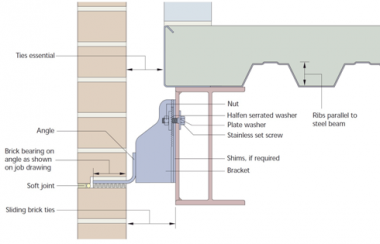
Brickwork support system at a steel edge beam.
(Image courtesy of Halfen Deha)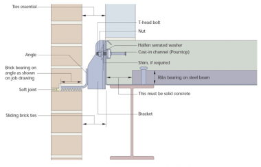
Brickwork support system at a slab edge in a composite steel framed structure.
(Image courtesy of Halfen Deha)


The eccentricity of the brickwork from its support is important because it determines the bending effect on the attachment points. The eccentricity is also dependent on the thickness of the insulation in the cavity space between the brickwork and the internal light steel walling. This maximum value is 120 to 150mm depending on the wall height. The brickwork is laterally supported by wall ties that attached to the infill walls at a density of about 4.4 ties per m2; of the facade area.
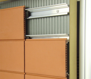
[top]Brick slip systems

(Image courtesy of Unite Modular Solutions)
Modern brickwork can be manufactured in the form of brick slips that are attached to a supporting steel sheet or composite panel. The advantage of this system is that it is lightweight and can be installed rapidly as mortar is not necessarily required. Brick slips can also be stacked vertically, and ribbon or unusual shaped windows can be created for architectural effect. Examples are shown in the photograph below.
In this system, the brick slips are not considered to be weather-tight, and so the wind and weather resistance is provided by the backing material. Composite (or sandwich) panels provide both excellent structural and thermal characteristics for use as the backing system.
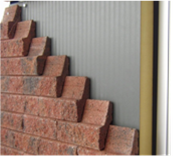

(Image courtesy of Kingspan Panels and profiles)
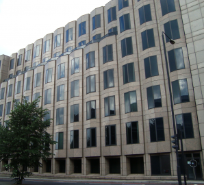
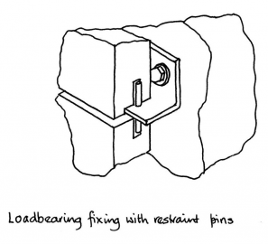
[top]Support from storey-height precast concrete panels
Masonry facades are also formed by supporting brick or natural “hand-set” stone panels from storey-height precast concrete panels. Stainless steel support brackets and restraining pins are used. Thicknesses of hand-set stone vary from 20 mm to 70 mm, depending on the wind load, the tensile strength of the stone and the spacing of fixings.
Continuous areas of masonry cladding have naturally low air permeability so generally air permeability is controlled by good detailing at interfaces with windows and doors and other penetrations through the wall for building services. Solar gain, light levels and views out are balanced by choosing appropriate window type, size and arrangement with suitable shading.
- Natural stone cladding and stainless steel fixing


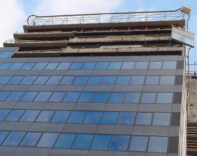
[top]Facade retention in building renovation
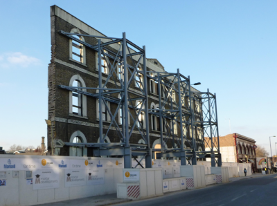

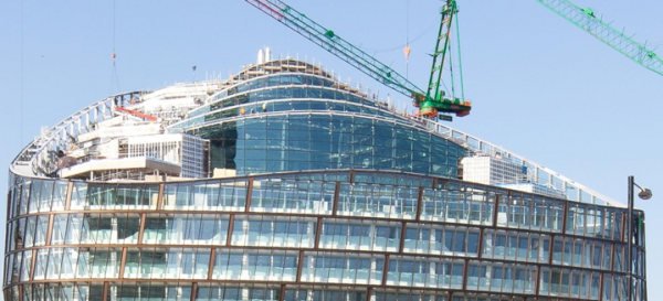
In many building renovation projects, the existing brick or stone façade is preserved and is supported temporarily by a steel structure, whilst the rest of the building is demolished. A new steel permanent structure is constructed behind the existing façade which is then integrated into the new building. In this way, the appearance of the building is not changed but its functional use is much improved. A good example of the support to an existing brick façade by an external temporary steel structure is shown below. The framework at ground level allows for pedestrian access.
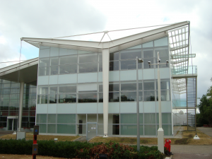
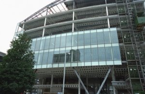
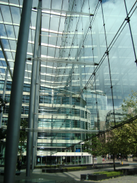
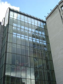
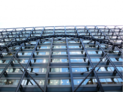
[top]Steel and glass facades

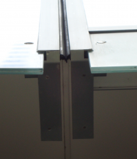
Steel and glass are synergistic materials and are often used in facades and roofs of multi-storey buildings. The glass panels are generally supported by separate vertical steel elements to the main structural frame of the building that may be internal or external to the building. Stainless steel and hollow steel sections are often used in combination with glass.
Fixing of glazed facade systems to steel frames
[top]Building performance

The glazed walling system is designed to provide the necessary functions of weather-tightness, natural lighting and shading, and thermal insulation. The silicone joints between the glazing panels are therefore very important to these functions.
The main issue in the design of glazing systems is the avoidance of high solar gain, particularly on south facing facades, and also the heat loss due to the relatively high U-value of double or even triple glazing systems that adds to heat loss. A modern argon filled double glazing system (combined with low emssivity glass) has a U-value of 1.6 to 1.8 W/m2K, and this can reduce to 0.8 to 0.9 W/m2K for high quality triple glazing systems.
Large glazing panels are usually supported by vertical mullions or in some cases, glass fins. The glass is designed to accommodate the movement of its support system due to the wind and other forces acting on it. Typical deflection limits under the design wind loads are defined by the Institution of Structural Engineers[3]
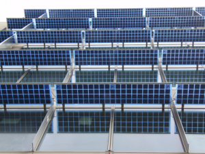
The glass elements may also be combined with louvres and bonded photovoltaic panels, as shown.
[top]Double-skin façade systems

Double-skin facades originated in northern Europe and are formed of two glass walls separated by a cavity on south-facing elevations and are used to reduce the energy consumption of a building. Shading devices are usually mounted in the cavity and, depending on its width, walkways for access and cleaning. This type of façade has many variations in arrangement. The variations relate to:
- width of cavity;
- type of glazing (single/insulating) for the inner or outer skins;
- division of the cavity horizontally and vertically;
- natural or mechanical ventilation of the cavity;
- integration of the cavity ventilation with the building services;
- use of opening windows into the cavity.
The two skins form a thermal buffer zone and passive solar gains in the cavity reduce heat losses in winter. If the cavity ventilation is integrated with the building services, air heated by the sun can be introduced into the building, providing good natural ventilation and reducing the heating load. In summer, the heated air in the cavity is ventilated to the outside, conducting heat away from the building and reducing the cooling load. The design of the double skin façade must be integrated with the design of the building services to be most effective.

(Image courtesy of Severfield (NI) Ltd.)
[top]Solar shading systems

(Image courtesy of Simon Doling/Feilden Clegg Bradley Architects. Copyright Simon Doling/Feilden Clegg Bradley Architects)
There is a wide variety of solar shading systems that may be used and incorporated as part of the building façade. There are:
- Oval shaped horizontal steel elements that span horizontally between external columns and their size and spacing is designed to reduce the intensity of solar gain.
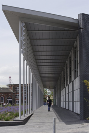
- Projecting roof or canopy , often supported by an external steel structure as shown.
- Glazed or metallic louvres.
- Metallic perforated screens that allow natural light to penetrate but also provide a high degree of shading.
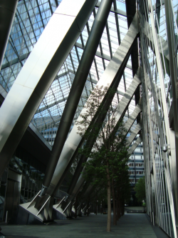
[top]Glazing support systems
Main article: Steel-supported glazed facades and roofs
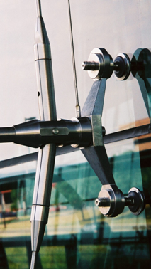
Modern glazing support systems are based on attachments to 2 or 4 separate glass panels using stainless steel brackets, also known as ‘spiders’ because of their multiple legs. The attachments to the glass panels are generally made by stainless steel brackets with neoprene gaskets through the glass, as shown below. These attachments permit articulation due to thermal and structural movements so that local stresses on the glass are minimised.
Glazing support structures can be of various forms:
- External or internal tubular columns that may be inclined
- Horizontal tubular or lattice members that span between widely spaced columns.
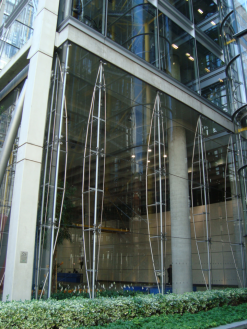
- Cable tied systems, as shown below, using stainless steel external couplers, arms and struts.
- Support system using stainless steel connectors
Corning Musem of Art, Corning, New York
(Images courtesy of TMR Consulting)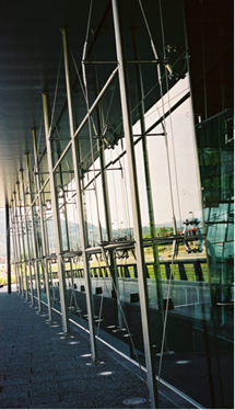


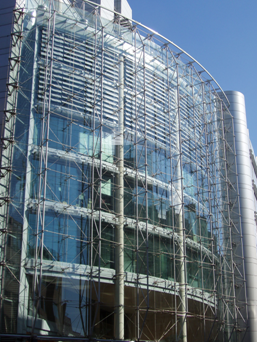
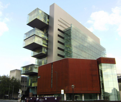
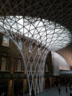
The Manchester Justice Centre shown below is a good example of the vertical and horizontal support by an internal tubular steel structure to a fully glazed façade over 8 storeys. Cable tied systems can be external or internal and use the cables to resist tension forces due to wind action on the façade and the tubular sections to resist compression. For minimum visual impact, the tubes should be of small diameter.

[top]Steel in atria and canopies
Main article: Steel-supported glazed facades and roofs
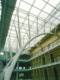

Atrium roofs and feature entrances are often supported by exposed structural steelwork detailed to provide visual excitement. Structural hollow sections are often used to form the elements because of their clean appearance. Also, stainless steel wires are used to minimise the intrusion of structure.
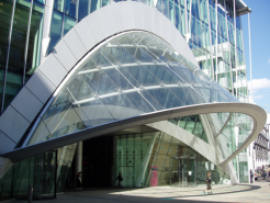
- Feature entrances


Glazed entrances are often made as transparent as possible to allow visual connection between the inside and outside of a building. Point-fixed glazing or glass fins may be used to increase transparency.

Glazed atrium roofs let light deep into a building allowing the use of large building footprints while reducing the external perimeter. Atria are also used to promote natural ventilation by the inclusion of opening vents in the roof. Warm air rising in the atrium and escaping through the vents draws outside air through open windows in the façade. Atria are used in offices with deep floor plans and are also a feature of shopping centres where retail units face onto a central atrium. Various glazing support systems are available including steel, aluminium or timber framing.
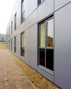
[top]Rain screen cladding
(Image courtesy of Kingspan Panels and Profiles)
A rain screen cladding system is usually drained and ventilated and consists of open-jointed, rail-mounted panels with an air-gap behind. The rails are supported by brackets from a backing wall which spans from floor to floor. The backing wall is either insulated itself or supports insulation mounted on its outside face. In the latter case, a membrane may be used to protect the insulation from moisture in the air gap.
Rain screen panels are made from durable materials and are chosen by the architect to achieve the desired visual effect. Stainless steel, weathering steel, anodised aluminium, glass and terracotta are all materials which can be used. Rails and brackets are made from materials such as stainless steel and aluminium. The backing wall resists wind actions and supports the rain screen and can consist of an infill wall made from cold-formed steel sections faced with cement particle board, precast or composite panels or blockwork.
Open jointed rain screen systems shed most of the rainwater from the surface of the rain screen panels. The open joints are wide enough to allow free ventilation of the air gap and any rainwater penetrating the joints between the panels is able to drain freely to the exterior. Residual moisture which does not drain away is able to evaporate freely.
- Metallic rain screen panels
Metallic rain-screen cladding attached to light steel infill walls


Window openings must be carefully flashed to direct water around them. The backing wall is sealed to control air permeability. Solar gain, light levels and views out are balanced by choosing appropriate window sizes and shading.
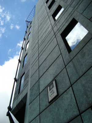
[top]Weathering steel rain screen cladding panels
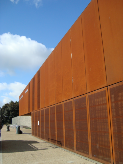
Sports centre
Residential building
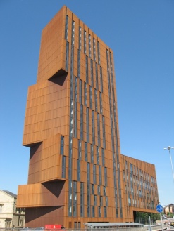
Broadcasting Place, Leeds


Rain water runoff from the surface of buildings clad in weathering steel is coloured red-brown by iron oxide and will stain the ground at the perimeter of the building. This effect reduces over time as the panels weather. Appropriate details around the building can be included to manage the staining. One approach that has been used is to include a gravel strip which has been renewed after a period of time.
[top]Insulated wall panels

Insulated wall panels are interlocking, composite metal-faced sandwich panels or concrete panels with insulation between internal and external concrete elements. Steel-faced insulated panels are frequently used on single storey and low-rise industrial buildings.
Panels are usually designed to span one-way (either vertically or horizontally) and are made to suit commonly-used frame spacings without intermediate supports. Various insulation materials are available such as expanded polyurethane (PUR), polyisocyanurate (PIR) and mineral fibre with a range of insulating, fire-resisting and other physical properties. Insulating materials should be selected with care, taking into consideration all the performance and functional requirements.. Various surface profiles and colours are available. Insulated wall panel systems have interlocking joints which include overlaps and compression gaskets to prevent water ingress.
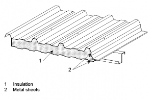
Insulated metal–faced panel
Horizontal-spanning sandwich panels


For horizontally-laid panels, vertical joints at supports are butt joints with compression gaskets and sealed or gasketted cover strips.
Insulated wall panels are a proprietary product and the manufacturer provides the results of test data which may be in the form of tables of span to wind pressure (or load) for various panel thicknesses, allowing the specifier to choose a suitable panel type and thickness.
[top]Insulated render
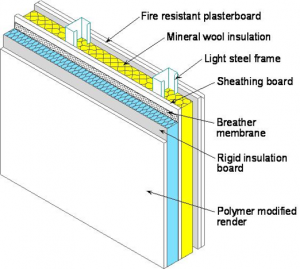

Insulated render, commonly known as External Wall Insulation (EWI) in North America has been in use in the UK for over 30 years. It has been used increasingly since 2000 to meet the demand for lightweight, energy efficient, architecturally interesting facades. Student accommodation and other residential and mixed-use buildings are often clad in this material.
Rigid insulation board is applied to a supporting frame and coated with a polymer-modified render which may be cement-based or acrylic-based and fibre reinforced. Light steel framing systems made from cold formed sections have increasingly been used to provide the supporting structure. Additional insulation can be placed within the depth of the framing. Early partial closure of the building is achieved by fixing cement particle board to the outer surface of the light steel framing system, prior to fixing the insulation.

Render systems form a face-sealed barrier and shed water from their external surface. They may be designed with or without a cavity depending on the degree of exposure of the building. Appropriate provision for drainage of a cavity must be made. Suitably detailed flashings and seals at penetrations for windows and doors are required. Further guidance is given in SCI P343.
[top]Interfaces
Main article: Facade supports and structural movements
Interfaces between steel frames and cladding systems may take various forms as follows:
- Brickwork support systems by Stainless steel angles and brackets.
- Attachment to curtain walling systems for both vertical and lateral support by the structure or the edge of the floor slab
- Attachment of steel hollow sections and cables in glazed cladding systems
- Projections for louvres or canopies, etc.
- Support to external steelwork
- Support to the atrium or featured steelwork.
These interface details are designed to take account of:
- Forces in the vertical and horizontal directions often combined with bending effects when used in louvers, etc.
- Allowance for relative movement with the support structure
- Allowance for installation tolerances in the alignment of the façade.
[top]Curtain walling support details
Curtain walling mullions are generally top-hung outside the edges of the floor slabs. The cladding brackets are usually fixed to the floor slab and are designed to resist both vertical and horizontal loads from the cladding self-weight and wind actions respectively. The brackets project beyond the floor edge and resist the weight of the cladding in bending and have to be sized appropriately. The fixing arrangements are required to be adjustable to allow the curtain walling panels to be properly aligned during installation. The fixings between the brackets and the mullions are designed to allow fine vertical adjustments.
The lower ends of the mullions are often sleeved into the mullions below to transfer horizontal forces but allow vertical movement.
[top]External steelwork
An external steel structure can be designed to be part of the primary structure or to support canopies or bracing. Often the external steelwork can be designed as unprotected against fire by considering the intensity and direction of potential fire plume emanating from the façade. Also, the external steelwork is designed to be part of the architectural concept, as shown below in Exchange Square, which straddles the railway lines to Liverpool station. In this project, the beams projected outside the façade line, and so penetrated the façade.
Such elements passing through an envelope or façade bridge the insulation and provide a potential path for moisture to pass into the building interior. One consequence of bridging the insulation is that local heat losses occur where the insulation is penetrated. A further consequence is that in cold weather, condensation occurs inside the building on the cold surfaces of the elements which communicate with the outside. This may result in visible staining and saturation of the insulation with consequent reduction in its performance.
Thermal performance and condensation issues can be avoided if suitable thermal breaks are introduced in the penetrating elements to keep their temperature inside the building above the dew point. Further guidance is given in SCI P380.
Where the forces in the elements are too large for a thermal break to be introduced, (for example because insulating materials are too flexible and weak) the penetrating element is insulated over a sufficient length inside the building for condensation not to occur.
On the Exchange Square project shown below the beams in the floor zone were insulated over a length of about 1.5m on the inside of the building for this reason.
[top]Louvres and canopies
Louvres and canopies are generally attached to the primary steel structure. To avoid cold bridging through the steel members passing through the insulation, the special thermal break details mentioned above are typically used, as shown below.
Canopies are often highly glazed as shown below and can be supported by a separate structure or suspended from the internal structure. Curved steel members (particularly hollow sections) are often used in canopies for visual effect.
- Steel interface details
External steelwork used in Exchange Square, Broadgate, London
Attachment points for external canopies using thermal break bolted details
Use of glass canopy supported by curved steelwork


[top]References
- ↑ Jump up to: 1.0 1.1 Standard for systemised building envelopes, Part 8 – Testing, March 2006, Centre for Window and Cladding Technology
- ↑ Technical standard L2, Measuring air permeability of building envelopes (Non Dwellings), 2010, Air Tightness Testing and Measurement Association
- ↑ Structural use of glass in buildings. 2nd edition (incorporating amendments), 2015. Institution of Structural Engineers
[top]Resources
- SCI P101 Interfaces: Curtain wall connections to steel frames
- SCI P102 Interfaces: Connections between steel and other materials
- SCI P103 Interfaces: Electrical lift installations in steel framed buildings
- SCI P166 Interfaces: Design of steel framed buildings for service integration
- SCI P193 Steel supported glazing systems
- SCI P298 Stainless steel masonry support systems- best practice information sheet for specifiers
- SCI P343: Insulated Render Systems Used With Light Steel Framing
- SCI P380, Avoidance of thermal bridging in steel construction
- SCI P396 New Beijing Poly Plaza Cable-Net Wall
- SCI IE P2 Services coordination with structural beams; Guidance on defect free interface