


Difference between revisions of "Expressed connections"
| (4 intermediate revisions by the same user not shown) | |||
| Line 12: | Line 12: | ||
==Conventional connection types== | ==Conventional connection types== | ||
''Main articles: [[Braced frames]], [[Continuous frames]], [[Simple connections]], [[Moment resisting connections]]'' | ''Main articles: [[Braced frames]], [[Continuous frames]], [[Simple connections]], [[Moment resisting connections]]'' | ||
| − | {{#image_template:image=File:Arch_fig63.png|caption=Example of a notched beam to beam connection for equal depth [[Steel_construction_products#Cellular beams|cellular beams]]|align=right|wrap=true|width=250}} | + | {{#image_template:image=File:Arch_fig63.png|caption=Example of a notched beam to beam fin plate connection for equal depth [[Steel_construction_products#Cellular beams|cellular beams]]|align=right|wrap=true|width=250}} |
| − | [[Simple_connections#Flexible end plate connections|Flush end plate connections]] that are [[Welding|welded]] to the flanges and web of the beam are commonly used as [[Simple_connections|nominally pinned connections]], although they do possess some bending resistance. Normally the end plate is 10 mm to 12 mm thick for use with M 20 bolts. When used as [[Moment_resisting_connections|moment connections]], the end plate is thicker, typically 15 – 20 mm, and is extended above the top flange to allow for | + | Partial depth end plates have an end plate welded only to the beam web. [[Simple_connections#Flexible end plate connections|Flush end plate connections]] that are [[Welding|welded]] to the flanges and web of the beam are commonly used as [[Simple_connections|nominally pinned connections]], although they do possess some bending resistance. Normally the end plate is 10 mm to 12 mm thick for use with M 20 bolts. When used as [[Moment_resisting_connections|moment connections]], the end plate is thicker, typically 15 – 20 mm, and is extended above the top flange to allow for an additional row of bolts to located outside the flange. Fin plates are simple rectangular plates, typically 10 mm thick, welded to the supporting member. The supported beams are simply cut and drilled (and notched if the support is a beam). |
| − | <gallery caption="Examples of common connection types" perrow=3 widths= | + | |
| − | Image:Arch_fig60.png|Connections to | + | For connections to [[Steel_construction_products#Structural hollow sections|Square Hollow sections]] (SHS), a form of expansion bolt connection may be used that forms a connection by expanding into the space behind the face of the section. However, the diameter of the expansion part of the bolts is up to twice that of the bolt diameter and so the spacing between the bolt holes has to be increased compared to normal bolts. Alternatively, proprietary 'blind' fixings may be used. |
| − | Image:Arch_fig61.png|Connections to | + | <gallery caption="Examples of common connection types" perrow=3 widths=200px heights=200px> |
| + | Image:Arch_fig60.png|Connections to UC and SHS columns using [[Simple_connections#Flexible end plate connections|flush end plates]] | ||
| + | Image:Arch_fig61.png|Connections to UC and SHS columns using [[Simple_connections#Fin plates|fin plates]] | ||
Image:Arch_fig62.png|Notched [[Simple_connections#Beam-to-beam and beam-to-column connections|beam to beam connection]] using [[Simple_connections#Flexible end plate connections|partial depth end plate]] | Image:Arch_fig62.png|Notched [[Simple_connections#Beam-to-beam and beam-to-column connections|beam to beam connection]] using [[Simple_connections#Flexible end plate connections|partial depth end plate]] | ||
</gallery> | </gallery> | ||
| Line 29: | Line 31: | ||
<br> | <br> | ||
The chords and bracing in a [[Trusses|truss]] or lattice girder are often [[Welding|welded]]. | The chords and bracing in a [[Trusses|truss]] or lattice girder are often [[Welding|welded]]. | ||
| − | {{#image_template:image=File:Arch_fig65.png|caption=Welded profiled connection between [[Steel_construction_products#Structural hollow sections|tubular sections]] in a [[Trusses#Warren truss|W-shaped roof truss]]|align=left | + | {{#image_template:image=File:Arch_fig65.png|caption=Welded profiled connection between [[Steel_construction_products#Structural hollow sections|tubular sections]] in a [[Trusses#Warren truss|W-shaped roof truss]]|align=left|width=200}} |
Where square [[Steel_construction_products#Structural hollow sections|hollow sections]] (SHS) are used then the ends of the SHS are cut to the required angle and [[Welding#Fillet welds|fillet welded]] to the face of the SHS chords. Where circular [[Steel_construction_products#Structural hollow sections|hollow sections]] (CHS) are used then the ends of the incoming CHS inclined members have to be cut to form the precise shape around the chords. This is known as [[Fabrication#Profiling of tubular sections|profiling]] which is a specialist process. | Where square [[Steel_construction_products#Structural hollow sections|hollow sections]] (SHS) are used then the ends of the SHS are cut to the required angle and [[Welding#Fillet welds|fillet welded]] to the face of the SHS chords. Where circular [[Steel_construction_products#Structural hollow sections|hollow sections]] (CHS) are used then the ends of the incoming CHS inclined members have to be cut to form the precise shape around the chords. This is known as [[Fabrication#Profiling of tubular sections|profiling]] which is a specialist process. | ||
The figure shows the use of a shaped [[Simple_connections#Fin plates|fin plate]] to provide more visual appeal to an otherwise simple connection between the top chord and bracing of a deep [[Trusses|truss]]. | The figure shows the use of a shaped [[Simple_connections#Fin plates|fin plate]] to provide more visual appeal to an otherwise simple connection between the top chord and bracing of a deep [[Trusses|truss]]. | ||
| − | |||
| − | |||
| − | |||
| − | |||
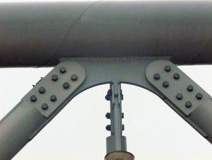
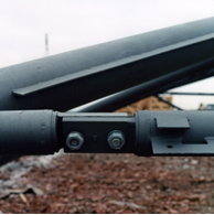
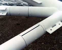
{{#image_template:image=File:Arch_fig66.png|caption=In-line connections between [[Steel_construction_products#Structural hollow sections|tubular sections]]|align=right|wrap=true|width=300}} | {{#image_template:image=File:Arch_fig66.png|caption=In-line connections between [[Steel_construction_products#Structural hollow sections|tubular sections]]|align=right|wrap=true|width=300}} | ||
| − | In-line connections are usually made by bolting, either by a flange plate with typically 4, 6 or 8 bolts (figure b), or a splice plate (figure c), or | + | In-line connections are usually made by bolting, either by a flange plate with typically 4, 6 or 8 bolts (figure b), or a splice plate (figure c), or an end plate (figure d), which can be concealed behind a cover plate. Various examples of these connections are shown below. |
| − | A | + | A profiled cover plate may be provided so that the connection is not visible, as shown below. |
<gallery caption="In-line connections between circular [[Steel_construction_products#Structural hollow sections|hollow sections]]" perrow=2 widths=250px heights=250px> | <gallery caption="In-line connections between circular [[Steel_construction_products#Structural hollow sections|hollow sections]]" perrow=2 widths=250px heights=250px> | ||
Image:Arch_fig67.png | Image:Arch_fig67.png | ||
| Line 79: | Line 77: | ||
*[[Media:SCI_P358.pdf|SCI P358 Joints in Steel Construction - Simple Joints to Eurocode 3, 2014]] | *[[Media:SCI_P358.pdf|SCI P358 Joints in Steel Construction - Simple Joints to Eurocode 3, 2014]] | ||
*[[Media:SCI_P398.pdf|SCI P398 Joints in Steel Construction - Moment-resisting Joints to Eurocode 3, 2013]] | *[[Media:SCI_P398.pdf|SCI P398 Joints in Steel Construction - Moment-resisting Joints to Eurocode 3, 2013]] | ||
| − | *[https://www. | + | *[https://www.tatasteeleurope.com/sites/default/files/Design%20of%20Structural%20Hollow%20Sections%20Welded%20Joints.pdf Design of welded joints - Celsius®355 and Hybox®355, 2013, Tata Steel] |
==See Also== | ==See Also== | ||
Latest revision as of 13:44, 11 March 2022
Various generic forms of connection may be used in steel frames. These include:

- Beam-to-column flange connections that may be moment-resisting
- Beam-to-beam web connections that are normally designed as nominally pinned
- Column-to-column splices
- Column bases at foundations
- Bracing connections.
Connection detailing depends on the forces and moments to be transferred, and on the chosen member sizes. However, some common detailing rules apply, which are discussed below, in order to gain an appreciation of the form of connections in regular frames.
[top]Conventional connection types
Main articles: Braced frames, Continuous frames, Simple connections, Moment resisting connections

Partial depth end plates have an end plate welded only to the beam web. Flush end plate connections that are welded to the flanges and web of the beam are commonly used as nominally pinned connections, although they do possess some bending resistance. Normally the end plate is 10 mm to 12 mm thick for use with M 20 bolts. When used as moment connections, the end plate is thicker, typically 15 – 20 mm, and is extended above the top flange to allow for an additional row of bolts to located outside the flange. Fin plates are simple rectangular plates, typically 10 mm thick, welded to the supporting member. The supported beams are simply cut and drilled (and notched if the support is a beam).
For connections to Square Hollow sections (SHS), a form of expansion bolt connection may be used that forms a connection by expanding into the space behind the face of the section. However, the diameter of the expansion part of the bolts is up to twice that of the bolt diameter and so the spacing between the bolt holes has to be increased compared to normal bolts. Alternatively, proprietary 'blind' fixings may be used.
- Examples of common connection types
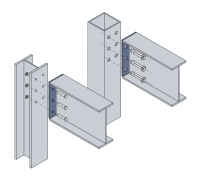
Connections to UC and SHS columns using flush end plates
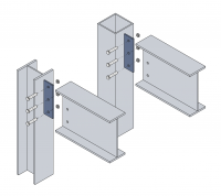
Connections to UC and SHS columns using fin plates
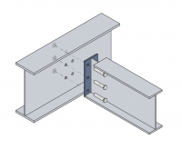
Notched beam to beam connection using partial depth end plate


[top]Tubular connections

Connections between tubular sections are often exposed and may take various forms:
- Beam-to-column connections that are usually bolted
- In-line connections that may be bolted or welded. In-line connections often occur in long members that require splicing for transportation.
- Tubular sections with welded fins
- Inclined connections such as inclined bracing to horizontal chords. These are usually welded.
The chords and bracing in a truss or lattice girder are often welded.
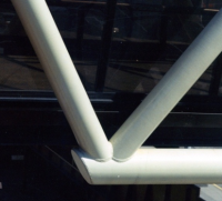

Where square hollow sections (SHS) are used then the ends of the SHS are cut to the required angle and fillet welded to the face of the SHS chords. Where circular hollow sections (CHS) are used then the ends of the incoming CHS inclined members have to be cut to form the precise shape around the chords. This is known as profiling which is a specialist process.
The figure shows the use of a shaped fin plate to provide more visual appeal to an otherwise simple connection between the top chord and bracing of a deep truss.
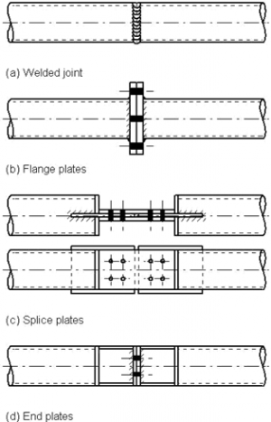

In-line connections are usually made by bolting, either by a flange plate with typically 4, 6 or 8 bolts (figure b), or a splice plate (figure c), or an end plate (figure d), which can be concealed behind a cover plate. Various examples of these connections are shown below.
A profiled cover plate may be provided so that the connection is not visible, as shown below.
- In-line connections between circular hollow sections


[top]Tie connections

Connections between ties that act in tension take two forms:
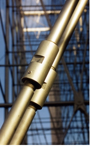
- Couplers which require that the rods are threaded in opposite directions so that the coupler can be tightened.
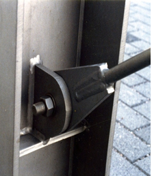
- Pins which may be welded to the rods or provided with threads. The pin is normally connected to a fin plate that is welded to another member.
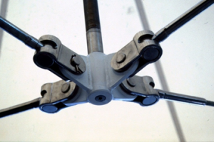
Rods and couplers are often stainless steel if exposed externally. Good examples of stainless steel tie rods used in the external façade of the Helsinki Sanomat building are shown. Where multiple connections between tie rods are required, special castings or fabricated nodes are necessary.
Rods may be connected by various types of cast and formed nodes. The detail shown is supported from above by a threaded rod and the horizontal nodes allow for articulation in two directions.
- Connections using stainless steel tie rods


Sanomat Building, Helsinki
[top]Further reading
- Steel Designers' Manual 7th Edition. Editors B Davison & G W Owens. The Steel Construction Institute 2012, Chapter 27, Joint design and simple connections
- Architectural Design in Steel – Trebilcock P and Lawson R M published by Spon, 2004
- Steel Buildings, BCSA No. 35/03, Chapter 4, Multi-Storey Buildings
[top]Resources
- SCI P167 Architectural Teaching Resource Studio Guide, 2000
- Best Practice in Steel Construction: Commercial Buildings
- Steel Buildings in Europe - Multi-storey buildings:
- EP37 Best Practice in Steel Construction – Industrial Buildings, Guidance for architects, designers & constructors
- Steel Buildings in Europe - Single storey buildings:
- SCI P358 Joints in Steel Construction - Simple Joints to Eurocode 3, 2014
- SCI P398 Joints in Steel Construction - Moment-resisting Joints to Eurocode 3, 2013
- Design of welded joints - Celsius®355 and Hybox®355, 2013, Tata Steel