Fire testing
A typical building contains a range of components and materials specified to enable designers to meet their legal obligations outlined in the Building Regulations and to create a safe and healthy environment. Those components which have a function in enabling the building to meet the requirements for life safety and property protection in fire must have a comparable standard of performance and must be fit for purpose. To demonstrate this, it is necessary that these materials and components undergo a standard fire test to failure which sets a common benchmark. In the UK, the standard fire test is specified in BS 476 Part 20[1]. An International Standards Organisation equivalent exists, ISO 834[2] and a European standard is also available, BS EN 1363-1[3].
When a claim is made that, for example, a fully loaded, fire protected, hot-rolled beam has 60 minutes fire resistance, this has a specific meaning. It does not mean that, in the event of a fire in a building, it will collapse after 60 minutes. Instead, in a floor furnace, loaded to its maximum capacity it simply allows a comparative assessment to be made with other products. The 60 minute resistance is the performance measured in the fire test.
[top]The standard fire test
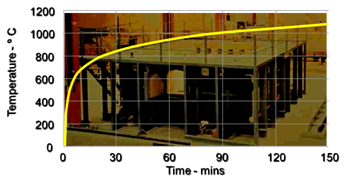
The time-temperature relationship in a standard fire test is internationally recognised and is the same regardless of the test standard used. It is defined as:
T = 345*Log(8*t+1) + 20
Where:
T is the temperature in degrees centigrade (°C) at a time (t) measured in minutes.
Furnaces which are nominally very similar can give very different results in a test. There are a number of reasons for this. The first is that it is possible to use different control mechanisms. Furnaces where the temperature is measured by, for example, a small bead thermocouple will respond very quickly to changes, especially in the early stages of a test, and will require only small increases in fuel input per unit change in recorded temperature. The other extreme is a furnace where the thermocouple is in the form of a plate. This presents a large area to the furnace which responds much more slowly than the smaller bead. Consequently, heating a furnace in accordance with the standard curve will demand more energy input if the temperature is measured with plate thermocouples, which react relatively slowly. Therefore tests in furnaces controlled by plate thermocouples will be much more severe than those controlled by the smaller, more responsive bead thermocouples, although both nominally follow the same time temperature relationship.
A second reason why apparently similar tests give very different results is the fuel used. This is usually gas or oil. Gas fired furnaces usually produce a clean environment in which the main mechanism of heat transfer is radiation from the walls to the test specimen. Oil fired furnaces can produce environments full of incandescent carbon particles which radiate to the specimen at higher temperatures than the walls. Therefore, an oil fuelled furnace will tend to be more severe than a gas fired equivalent.
In the late 1990s, CEN Technical Committee 127 (Fire safety in buildings) was tasked with developing a control mechanism for furnaces which could be included in a fire test standard, the use of which would ensure that all test furnaces within the European Union were of equal severity. The solution TC 127 developed was the plate thermocouple and this is now specified in BS EN 1363-1[3].
Extensive information on the requirements for fire testing, methods of testing, process of certification and extended application of results is available from the Association for Specialist Fire Protection (ASFP) website.
[top]Success and failure in fire testing
The reports on fire resistance tests generally outline results expressed in terms of time to failure against one or more of three criteria for the product/element being considered. The performance criteria are:
- Load bearing capacity, i.e. the ability to support the applied load and to resist collapse
- Integrity, i.e. the ability to resist the passage of flames/hot gases. Integrity failure is determined by an ignition test using a cotton pad, or penetration of a gap gauge into openings, or by the presence of sustained flaming through an opening.
- Insulation, i.e. the ability to restrict the temperature rise on the unexposed face. Insulation failure occurs when that the average temperature rise on the unexposed face exceeds 140°C above the initial average temperature and at no point is the temperature increase on the unexposed face allowed to be greater than 180°C above the initial average temperature.
Some building elements require that all three criteria are met, others two and some only one. An example of elements which are generally required to meet only one of the performance criteria are structural columns. These are required to demonstrate only that they can carry the load without collapsing for the duration of the fire test (load bearing capacity). In this case, structural failure in a fire test is determined by exceeding certain levels and rates of vertical contraction. The limiting deflection (C) for flexural loaded elements is defined in BS EN 1363-1[3] as:
C = h/100 mm
And the limiting rate of deflection (dC/dt) as:
dC/dt = 3h/1000 mm/min
where h is the initial height of test specimen in mm.
An example of an element which is required to meet all three performance criteria is a structural floor between two fire compartments. Such floors must demonstrate that they will carry the load without collapsing for the duration of the fire test (load bearing capacity). They must also demonstrate that they will not crack and allow the passage of smoke and hot gases from the fire affected compartment (integrity). Floor constructions must demonstrate that the temperature on the unaffected side must remain within the prescribed limits (insulation). On occasions, (in particular with composite steel deck floors), it is this insulation criterion, rather than structural resistance, which dictates the thickness of the slab.
Structural failure in a floor slab or beam in a fire test is determined in terms of exceeding certain limiting levels and rates of deflection. The limiting deflection (D) for flexural loaded element is defined in BS EN 1363-1[3] as:
D = L²/400d mm
And the limiting rate of deflection (dD/dt)as:
dD/dt = L²/9000d mm/min
where:
L is the length of the test specimen in mm
d is defined as the distance from the extreme fibre on the cold design compression zone to the extreme fibre on the cold design tension zone of the structural section, in mm.
Failure to support the load is deemed to have occurred when both of these criteria have been exceeded.
- Fire testing
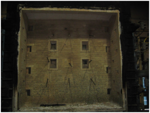
A horizontal furnace, typically for testing floor slabs, beams etc.
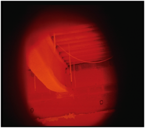
(Image courtesy of Exova Warringtonfire)Inside a furnace during a fire test on a spray protected beam
[top]Other standard fire tests
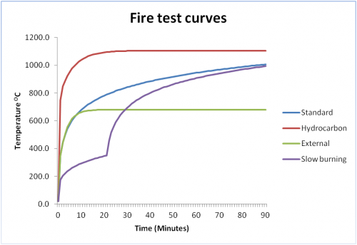
Fire test curves such as that described in BS 476 Part 20[1] are suitable for testing materials or systems which will be used in typical building fires (often referred to as cellulosic fires). However, some fires occur in situations where that time-temperature relationship may not be suitable. In that case, different time-temperature exposures are required for the test which demonstrates fitness for purpose. For example, fires based on hydrocarbon fuels are characterised by very rapid temperature increases. It follows therefore that fire resistant materials or systems which must resist this type of fire should be tested to a time-temperature relationship in which very high temperatures are reached very quickly. This is the hydrocarbon curve and details are contained in the appropriate standard[4]. Tunnel fires are also very severe and may contain considerable amounts of hydrocarbon material. The added complication with tunnels is that the environment is effectively inside a tube and the heat has no place to which it can escape. This leads to a high build-up of temperature and pressure. Extensive testing has led to the development of a series of test curves which are in common use. See External links
Slow burning fire tests[5] are required for materials that are reactive under the influence of fire.
External fire curves[4] are used in the testing of materials which are exposed to fire through the facade. They reflect the fact that fires in compartments will not be as severe at the point where they vent to the outside atmosphere as they will be internally.
[top]Limitations of the standard fire test
The concept of the standard fire test has been used to establish fire performance for over 100 years. In that time, it has proven to be of great value and it continues to underpin the testing and assessment of the great majority of fire resisting materials and systems used in buildings. However, it is not perfect and has a number of shortcomings.
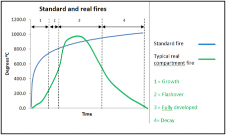
The most obvious of these is the nature of time-temperature relationship in the standard fire test, which bears little relationship to what happens in most real fires. It can be seen (right) that the temperature in a standard fire rises quickly and then increases indefinitely. In practice this will almost certainly never occur. In a real fire, once the combustible material (the fire load) has been consumed, the fire will decay and the temperature will reduce.
The severity of a fire in a compartment is also related to both fire load and ventilation, neither of which is considered in a standard fire test. Real fires are either load or ventilation controlled. A fire in a compartment which has a low fire load is unlikely to cause a threat to structural integrity. Similarly, if a fire occurs in a compartment with a high fire load but very low levels of ventilation, this is also unlikely to threaten the structure; both these scenarios however, may present a threat to life.
Fires in real building compartments do not usually occur in all places with maximum severity at once. Instead, a fire will burn most severely where the balance of fire load and ventilation allow it to do so with optimum efficiency. The fire will then reduce in the original location and (if not controlled) develop elsewhere. This means that, in many fires, it is likely that limited areas of the building will be subject to the full force of the fire at any time, and then only for a limited period. In a multi-storey building with horizontal (floor) compartmentation, the fire is most likely to move from the point of origin to the point of optimum ventilation (probably near the windows), and when the fuel has been consumed at those places, it will move into the areas of the compartment where there is less ventilation. This means that, when a fire consumes a compartment over a period, it is likely that no part of the structure of the compartment will be subjected to the maximum severity of the fire for the whole of that time. Research indicates that travelling fires are generally likely to be less severe that fires which are assumed to engulf the whole compartment. A non-uniform fire is not less severe - in some instances non-uniform heating across a compartment floor was shown to cause a failure mechanism in the structure, which might not occur if uniform temperatures were applied[6].
Fire can cover an entire compartment with equal severity in buildings with large, open compartments, good ventilation and high fire load, for example a single storey building used for storage.
Wall linings in real fires also have a significant impact on severity and this is not taken into account in the standard fire test. Heavy, high density walls are likely to absorb more energy than low density equivalents and this will reduce fire severity.
The biggest difference between the standard fire test and real fires is in the effect of continuity. Standard fire tests in the UK are generally carried out on discrete, simply supported elements of structure. Real buildings consist of assemblies of connected components and modern composite steel deck floor structures in particular are effectively continuous. The Cardington large scale fire tests and an investigation by the Steel Construction Institute into a fire at a composite steel deck building at Broadgate Phase 8 in London in 1990 (see SCI P113), have shown that the inherent fire resistance of this common structural framing system is far greater than is demonstrated using standard fire tests. In the Cardington large scale fire tests in particular, it was shown that unprotected beams which would fail in less than 20 minutes in a simply supported standard fire test could survive severe natural fires to give over one hour fire resistance. This finding underpins much of modern structural fire engineering.
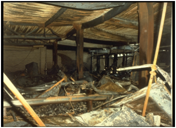
The aftermath of the fire at Broadgate Phase 8 in London. The building was only partially protected and, based on the performance of individual element tests, should have collapsed. However, it did not do so and exhibited considerable robustness. The damage shown here was repaired and the structure reinstated.
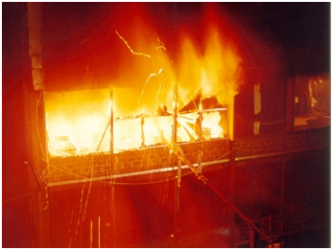
A typical scene from the Cardington fire tests, which demonstrated the inherent robustness of composite steel deck construction
[top]Natural fire tests
Over the past three decades, a large number of natural fire tests (i.e. tests using fire load made up of material which might normally be found in a building) have taken place across the world, the great majority of which have been on steel framed buildings.
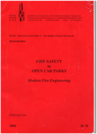
Some of the early large scale natural tests were on open sided car parks and were carried out demonstrate that fires in these buildings did not spread from car to car to create levels of heat and radiation which would threaten the structure. It was as a direct result of these tests that a structural fire resistance requirement of 15 minutes for open sided car parks was introduced in the UK. The details of the fire test were collated and published by the European Convention for Constructional Steelwork[7].
A range of natural fire tests were carried out in the UK between the early 1980s and the early 2000s. These included:
- The Cardington large scale fire tests, which were conducted on an 8 storey composite steel deck frame
- A large scale test on a shallow floor assembly.
- A series of large compartment fire tests carried out between 1983 and 1986 to investigate the behaviour of structural steel in natural fires.
- A series of fire tests carried out in conjunction with the Building Research Establishment to investigate natural fires in large scale compartments.
- A natural fire test from 1986 on a loaded steel frame assembly.
Full details of all these tests, including full descriptions and all the data can be downloaded from the article on steel in fire data
[top]References
- ↑ 1.0 1.1 BS 476-20: 1987, Fire tests on building materials and structures. Method for determination of the fire resistance of elements of construction (general principles). BSI
- ↑ ISO 834-1: 1999, Fire-resistance tests - Elements of building construction. General requirements. International Standards Organisation
- ↑ 3.0 3.1 3.2 3.3 BS EN 1363-1: 2020, Fire resistance tests. General requirements. BSI
- ↑ 4.0 4.1 BS EN 1991-1-2: 2002, Eurocode 1. Actions on structures. General actions. Actions on structures exposed to fire. BSI
- ↑ PD 7974-1: 2019, Application of fire safety engineering principles to the design of buildings. Initiation and development of fire within the enclosure of origin (Sub-system 1). BSI
- ↑ Travel Guide. J Stern-Gottfried, G Rein, JL Torero. Fire Risk Management, Nov 2009, pp. 12-16
- ↑ 7.0 7.1 ECCS Technical Committee 3 - Fire safety of steel structures: Fire safety in open car parks. No. 75. 1993. European Convention for Constructional Steelwork
[top]Further reading
- Guide to the Advanced Fire Safety Engineering of Structures. Institution of Structural Engineers, 2007.
- Travelling fires for structural design. Stern-Gottfried, J.Ubiversity of Edinburgh, August 2011.
[top]Resources
- Steel construction - Fire Protection supplement, 2013
- SCI P113 Structural fire engineering: Investigation of Broadgate Phase 8 fire
[top]See also
- Calculating section factors
- Car parks in fire
- Fire protecting structural steelwork
- Structural fire engineering
- Structural fire resistance requirements
[top]External links
- Association for Specialist Fire Protection
- Information on time-temperature relationships for hydrocarbon and tunnel fires
- European Committee for Standardisation (CEN)


