Difference between revisions of "Fire protecting structural steelwork"
| Line 121: | Line 121: | ||
===Slim floor beams=== | ===Slim floor beams=== | ||
{{#image_template:image=File:Protected_Slimflor.png|align=left|wrap=true|caption=Protected 'Slim floor' beam with [[Floor_systems#Precast_units|precast concrete planks]]|width=250}} | {{#image_template:image=File:Protected_Slimflor.png|align=left|wrap=true|caption=Protected 'Slim floor' beam with [[Floor_systems#Precast_units|precast concrete planks]]|width=250}} | ||
| − | There are a number of shallow floor solutions using ‘integrated’ beams. The beams may either be rolled or fabricated, and a number of alternatives are available. One such fabricated beam consists of an [[Steel construction products#Standard_open_sections|H section]] (usually UC) with a welded bottom plate – this is often called a ‘Slim floor beam’. Others include [ | + | There are a number of shallow floor solutions using ‘integrated’ beams. The beams may either be rolled or fabricated, and a number of alternatives are available. One such fabricated beam consists of an [[Steel construction products#Standard_open_sections|H section]] (usually UC) with a welded bottom plate – this is often called a ‘Slim floor beam’. Others include [https://www.kloecknermetalsuk.com/westok/products/ultra-shallow-floor-beam/ Ultra Shallow Floor Beams] (USFB) from Kloeckner Westok, and ArcelorMittal's [http://sections.arcelormittal.com/fileadmin/redaction/4-Library/1-Sales_programme_Brochures/SlimFloor/SlimFloor_EN.pdf Slim floor beams]. The common theme is that the beams are asymmetric with a wider bottom flange than top flange to carry the deck slab, which may be either precast concrete (pc) units, or a deep deck composite slab. |
A key feature of such shallow floor systems is that almost the whole steel section is protected from the fire by the floor slab and up to [[Structural_fire_resistance_requirements|60 minutes fire resistance]] is achievable without protection to the exposed bottom plate. | A key feature of such shallow floor systems is that almost the whole steel section is protected from the fire by the floor slab and up to [[Structural_fire_resistance_requirements|60 minutes fire resistance]] is achievable without protection to the exposed bottom plate. | ||
Revision as of 11:54, 12 March 2019
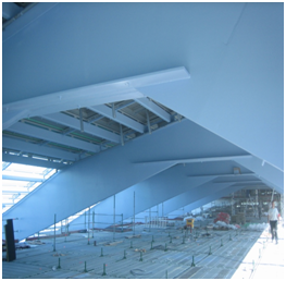
Passive fire protection materials insulate steel structures from the effects of the high temperatures that may be generated in fire. They can be divided into two types, non-reactive, of which the most common types are boards and sprays, and reactive, of which thin film intumescent coatings are the most common example. Thin film intumescent coatings can be either on-site or off-site applied.
The UK is fortunate in having an efficient and competitive structural fire protection industry which delivers excellent quality at low cost.
(Image courtesy of Sherwin-Williams Protective and Marine Coatings)
[top]Intumescent Coatings
Intumescent coatings are paint like materials which are inert at low temperatures but which provide insulation as a result of a complex chemical reaction at temperatures typically of about 200-250°C. At these temperatures the properties of steel will not be affected. As a result of this reaction they swell and provide an expanded layer of low conductivity char.
Intumescent coatings can be divided into two broad families: thin film and thick film. Thin film materials are either solvent based or water based and are mainly used for building fires. Thick film intumescent coatings were originally developed for the off-shore and hydrocarbon industries but have been modified for use in buildings.
[top]Thin film intumescent coatings
Thin film intumescent coating systems generally have three components, a primer, a basecoat (the part which reacts in the fire) and a sealer coat. The basecoat usually comprises the following ingredients:
- A catalyst which decomposes to produce a mineral acid such as phosphoric acid.
- A carbonific such as starch which combines with the mineral acid to form a carbonaceous char.
- A binder or resin which softens at a predetermined temperature.
- A spumific agent which decomposes together with the melting of the binder, to liberate large volumes of non-flammable gases. These gases include carbon dioxide, ammonia and water vapour. The production of these gases causes the carbonaceous char to swell or foam and expand to provide an insulating layer many times the original coating thickness.
They are mainly used in buildings where the fire resistance requirements are 30, 60 and 90 minutes. In recent years, a number of products have been developed which can provide 120 minutes fire resistance . They can be applied either on-site or off-site.
In general, most on-site application is carried out using water based materials. However, where the structure to which the material is applied is not to have an end use in a dry, heated (C1) environment, solvent based materials are commonly used. Solvent based materials also tend to be able to cover a wider range of section factors than water based materials and can be used on-site to protect smaller sections requiring high thicknesses.
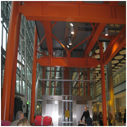
Both solvent based and water based coatings can be used to achieve attractive surface finishes. If a decorative or bespoke finish is required, this should be included in the specification. Thin film intumescents have the added advantages that they can easily cover complex shapes and post-protection service installation is relatively simple.
Typical expansion ratios are about 50:1, i.e. a 1mm thick coating will expand to about 50mm when affected by fire.
Detailed guidance on the specification and installation of site applied, thin film intumescent coatings is available from the Association for Specialist Fire Protection[1].
- Examples of thin film intumescent coating
[top]Off site applied intumescent coatings
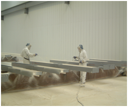
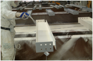
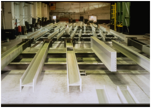
The development of an industry to apply thin film intumescent coatings off-site has been a UK success story which is now being exported across the world. The process usually involves application in a large, well ventilated and heated facility remote from the construction site. It has a number of distinct advantages:
- Quicker construction
- Improved quality control
- Reduction in site disruption
- Cleaner sites
- Improved site safety
- Easier servicing installation
Specifiers should be aware that off-site applied thin film intumescent coatings are used mainly for non-aesthetic end uses. Aesthetic finishes are possible, and have been achieved, using off-site application but it requires an additional level of care and attention. This is because some damage in transit is inevitable, even though applicators work to minimise it. It is difficult (but not of course impossible) to repair damage to match the appearance of the rest of the coating but this adds a layer of complexity to the work.
Applying thin film intumescent coatings off-site is a specialised task. The Association for Specialist Fire Protection publishes a guidance document[2] to assist specifiers. This includes a model specification from which clauses can be taken to put in the specifier’s own contract documents.
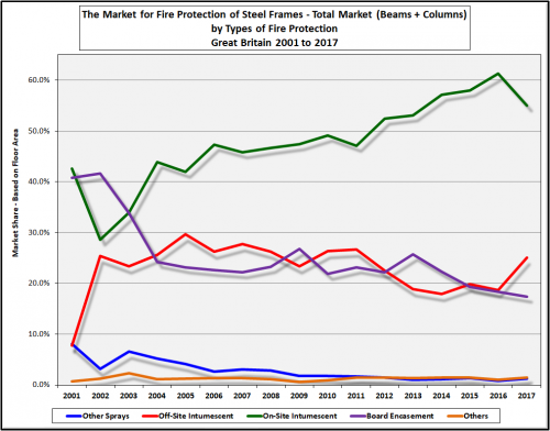
Off-site application is more expensive than its on-site equivalent in terms of up-front costs but the value of the advantages can make it more cost effective overall. This is widely recognised and market surveys show that this process has a significant market share in the UK.
- Application of thin film intumescent coatings offsite
[top]Thick film intumescent coatings
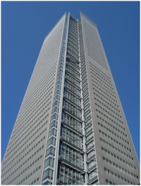
The New York Times HQ with thick film epoxy fire protection to the exterior steel
(Image courtesy of International Paint)
Thick film intumescent coatings are usually epoxy based and typically have a much higher dry film thickness than thin film alternatives. These materials are tough and durable and were originally developed for use with hydrocarbon fires, where the test heating regime is much more severe than that used for most industrial and commercial applications. A number of manufacturers have modified their materials for use in cellulosic fires. These modified materials are usually used in situations where the benefits of intumescent coatings in terms of appearance, weight and thickness are required but where circumstances are too severe, or maintenance too difficult, to allow the use of thin film materials . Typical recent examples have occurred in external steel in high rise buildings and exposed marine environments.
Expansion ratios for thick film intumescents are much lower than for thin film materials, typically about 5:1. Aesthetic finishes are possible and it can also be supplied in the form of preformed casings. Thick film intumescent coatings can also be applied off-site.
[top]Boards
(Image courtesy of Promat Ltd.)
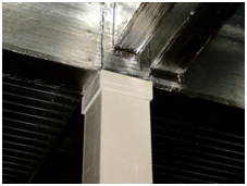
Boards are widely used for structural fire protection in the UK. They are used both where the protection system is in full view and where it is hidden. They offer the specifier a clean, boxed appearance and have the additional advantages that application is a dry trade and may not have significant impacts on other activities. Also, boards are factory manufactured and thicknesses can be guaranteed. Furthermore, boards can be applied on unpainted steelwork.
There are broadly two families of board protection, lightweight and heavyweight. Lightweight boards are typically 150-250kg/m³ and are not usually suitable for decorative finishes. They are typically used where aesthetics are not important and are cheaper than heavyweight equivalents. Heavyweight boards are usually in the range 700-950kg/m³ and will generally accept decorative finishes. They are typically used where aesthetics are important.
Both types of board may be used in limited external conditions but the advice of the manufacturer should be sought. Detailed guidance on the installation of board protection systems is available from the Association for Specialist Fire Protection[3].
- Board protection systems
[top]Sprays
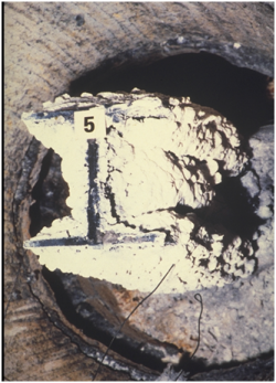
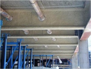
Spray protection is extensively used in the United States but is less common in the United Kingdom. It has the advantage that it can be used to cover complex shapes and details and also that costs do not increase significantly with increases in protection thickness. This is because much of the cost of application is in the labour and equipment and a minority is in the cost of the material. Some materials can also be used in external and hydrocarbon fire applications.
Sprays are not suitable for aesthetic purposes. Also, application is a wet trade and this may have impacts on other site operations. Allowance may have to be made in costing for the possible requirement for prevention of overspray. Detailed guidance on the installation of spray protection systems is available from the Association for Specialist Fire Protection[4].
[top]Flexible blanket systems
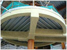
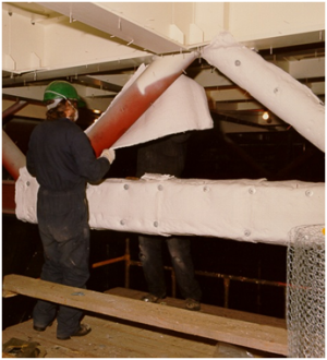
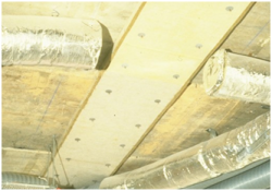
Flexible fire protection systems have been developed as a response to the need for an easily applied fire protection material which can be used on complex shapes and details but where application is a dry trade. There are a limited number of manufacturers of these products. Fixing of a blanket is shown in the accompanying photograph.
[top]Concrete encasement
Until the late 1970s, concrete was by far the most common form of fire protection for structural steelwork. However the introduction of lightweight, proprietary systems such as boards, sprays and thin film intumescent coatings has seen a dramatic reduction in its use. Nevertheless, concrete encasement has its place and it continues to have a small percentage of the fire protection market with other traditional methods such as blockwork encasement also used occasionally. The principal advantage of concrete is durability. It tends to be used where resistance to impact damage, abrasion and weather exposure are important e.g. warehouses, underground car parks and external structures. The principal disadvantages are:
- Cost - compared to lightweight systems;
- Space utilisation (large protection thicknesses take up valuable space around columns)
- Weight.
Information on thickness of concrete encasement for specific periods of fire resistance is published by the Building Research Establishment[5]. It can also be found in BS EN 1994-1-2[6].
[top]Partial protection
Standard fire tests have shown that structural members which are designed to not be fully exposed to fire can exhibit substantial levels of fire resistance without applied protection. Methods have been developed using this effect to achieve 30 and 60 minutes fire resistance. Where higher periods of fire resistance are called for, reduced fire protection thicknesses can be applied to the exposed steelwork since the heated perimeter, and therefore the section factor, is less than that for the fully exposed case. See here for more details.
There are five ways in which partial protection can be used:
[top]Block infilled columns
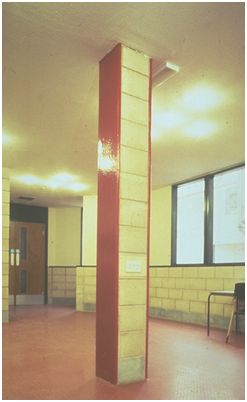
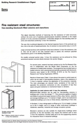
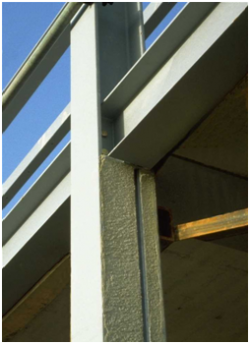
30 minutes fire resistance can be achieved by the use of autoclaved, aerated concrete blocks cemented between the flanges and tied to the web of rolled sections. Longer fire resistance periods are possible by protecting only the exposed flanges. Guidance is available from the Building Research Establishment[7].
[top]Shelf angle floor beams
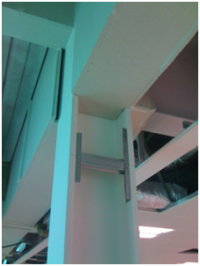
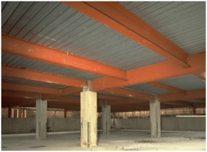
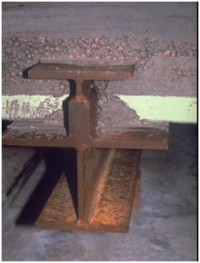
Shelf angle floor beams are beams with angles welded or bolted to the web to support the floor slab. This protects the top part of the beam from the fire while the bottom part remains exposed. Fire resistance increases as the position of the supporting angle is moved further down the beam and 60 minutes fire resistance is achievable in some instances. Shelf angle floor beams are more commonly bolted rather than welded as shown in the accompanying photograph.
Guidance is available in SCI P126.
[top]Slim floor beams
There are a number of shallow floor solutions using ‘integrated’ beams. The beams may either be rolled or fabricated, and a number of alternatives are available. One such fabricated beam consists of an H section (usually UC) with a welded bottom plate – this is often called a ‘Slim floor beam’. Others include Ultra Shallow Floor Beams (USFB) from Kloeckner Westok, and ArcelorMittal's Slim floor beams. The common theme is that the beams are asymmetric with a wider bottom flange than top flange to carry the deck slab, which may be either precast concrete (pc) units, or a deep deck composite slab.
A key feature of such shallow floor systems is that almost the whole steel section is protected from the fire by the floor slab and up to 60 minutes fire resistance is achievable without protection to the exposed bottom plate.
Where periods of fire resistance greater than 60 minutes are required, only the exposed bottom flange or plate or the beam requires protection. The section factor is calculated on the basis of the heated perimeter of the bottom flange or plate.
[top]Web infilled columns
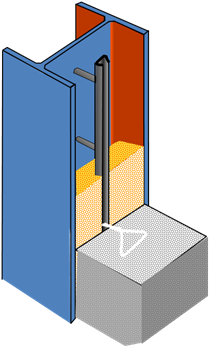
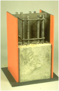
Sixty minutes fire resistance can be achieved for columns when normal weight, poured concrete is fixed between the flanges by shear connectors attached to the web. The concrete is retained by a web stiffener fixed at the bottom of the connection zone.
The load carrying capacity of the concrete is ignored in the design of the columns but in fire, as the exposed steel weakens at high temperatures, the load carried by the flanges is progressively transferred to the concrete. This provides stability for periods of fire resistance up to 60 minutes . The connection zone is fire protected along with the beam. Guidance is available in the Steel Construction Institute publication SCI P124.
- Web infilled columns
[top]Composite beams and columns with full and partial concrete encasement
This is a form of construction which has been introduced to the UK by the publication of BS EN 1994-1-2[6], which describes the systems and also includes tabulated design guidance. It consists of steel beams and columns in which fire resistance is achieved by the inclusion of reinforcement between the flanges, held in position by concrete. Fire resistance periods up to 120 minutes is achievable on columns using this approach and 180 minutes on beams. Guidance is also given on enhancement to full concrete encasement by the inclusion of rebar and up to 240 minutes fire resistance can be achieved. However, this requirement is rare in the UK.
[top]Protecting cellular beams
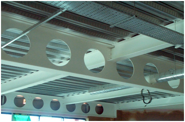
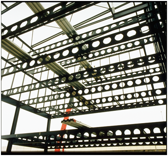
For many years, beams with multiple web openings manufactured by splitting and welding hot rolled beams and columns (castellated and cellular beams), were fire protected on the basis of the section factor of the parent section plus 20%. This was based on the results of a number of tests on castellated beams which showed a small increase in heating rate compared to hot rolled sections. When a process of manufacturing cellular beams from plates was developed, the 20% rule was retained. The default limiting temperature for cellular beams was taken as being the same as for hot rolled beams carrying concrete slabs, i.e. 620°C for thin film intumescent coatings and 550°C for sprays and boards.
However, over time, additional testing showed that cellular beams can display complex failure mechanisms in fire. A much improved understanding of these mechanisms has now been developed and, from this, it has become clear that the assumption that the limiting temperature of such beams is the same as for unperforated sections is not correct. Instead it has been shown that the geometry of the beam defines the limiting temperature and that every cellular beams needed to be assessed on its own merits. Generalised (or universal) solutions are not appropriate.
The great majority of cellular beams are fire protected using thin film intumescent coatings. The Association for Specialist Fire Protection (ASFP) and the Steel Construction Institute (SCI) have developed structural models for beams with circular and rectangular web openings. These models enable the calculation of the limiting temperature as a function of beam geometry and load. This can then be used to determine the correct intumescent coating thickness for the required fire resistance period, based on a section factor calculated using the formula:
Section factor = 1400/t
where t is the web thickness in mm.[Note: in situations where the web thickness varies, this is the bottom web thickness]
Some cellular beam manufacturers will also supply limiting temperatures for their products. The ASFP publishes details of the test protocol that thin film intumescent coating manufacturers must follow if their material is to be used on cellular beams[8]. This has separate parts for testing on beams with circular and rectangular openings. Thin film intumescent coatings which are to be used on beams with circular web openings must be tested to that part of the protocol but thin film intumescent coatings which are to be used on beams with rectangular openings must be tested to both parts.
Only thin film intumescent coatings which have been tested to the ASFP protocol can be used to fire protect cellular beams. The exception to this is where it can be shown that a beam and/or thin film intumescent coating manufacturer have developed their own structural model and design software which specifies particular thin film intumescent coatings tested by them and independently third party certified.
Specifiers should always request confirmation that the performance of thin film intumescent coatings intended for use on their project has been tested and assessed for use on beams with web openings as required.
In rare instances, cellular beams are protected by sprays or boards. Advice on specification of fire protection in this instance is given in the ASFP guidance[8].
Consideration should also be given to filling of voids for cellular beams.
[top]Trends in structural fire protection
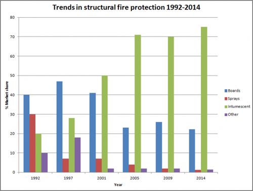
The most obvious trend in structural fire protection for steel over the past two decades has been the rise in popularity of thin film intumescent coatings. This has been driven by an intensely competitive industry which has in turn driven R&D. This has created an impetus behind better, cheaper, thinner materials to the point where, in real terms, costs are a fraction of what they were in the 1990s. This has also been helped by the development of off-site applied intumescent coatings which has given manufacturers a new market.
- Trends in structural fire protection
[top]Case studies
[top]References
- ↑ ASFP Technical Guidance Document – TGD 11. Code of practice for the specification & on-site installation of intumescent coatings for fire protection of structural steelwork
- ↑ ASFP Technical Guidance Document - TGD 16. Code of Practice for Off-site Applied Thin Film Intumescent Coatings
- ↑ ASFP Technical Guidance Document - TGD 14. Code of practice for the installation and inspection of board systems for the fire protection of structural steel work
- ↑ ASFP Technical Guidance Document – TGD 15. Code of practice for the installation & inspection of sprayed non-reactive coatings for the fire protection of structural steelwork
- ↑ Guidelines for the Construction of Fire Resisting Structural Elements. Building Research Establishment.
- ↑ 6.0 6.1 BS EN 1994-1-2: 2005+A1:2014, Eurocode 4. Design of composite steel and concrete structures. General rules. Structural fire design. BSI
- ↑ BRE Digest 317. Fire resistant steel structures: free-standing blockwork-filled columns and stanchions. Building Research Establishment
- ↑ 8.0 8.1 8.2 Fire protection for structural steel in buildings (5th ed). The Association for Specialist Fire Protection.
[top]Further reading
- Passive & reactive fire protection to structural steel. Lennon, T. & Hopkin, D. Building Research Establishment
[top]Resources
- Steel construction - Fire Protection supplement, 2013
- SCI P126 The fire resistance of shelf angle floor beams to BS5950 Part 8, 1993
- SCI P124. The fire resistance of web-infilled steel columns, 1992


