Difference between revisions of "One Angel Court, London"
(Created page with "==Article in [http://www.newsteelconstruction.com/wp/wp-content/uploads/digi/NSCSept2016digi/pubData/mobile/index.htm#/20/ NSC September 2016]== {{#image_template:image=File:One_...") |
|||
| Line 56: | Line 56: | ||
|} | |} | ||
| − | [[Category:Case studies | + | [[Category:Case studies - Multi-storey office buildings]] |
Revision as of 12:30, 12 March 2019
Article in NSC September 2016
Rebuilding a City tower
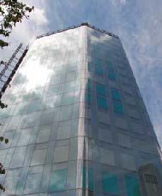
Situated within the Bank of England Conservation Area, the 1970s-built One Angel Court is being rebuilt with a steel frame to create a standout City of London office scheme.
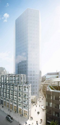
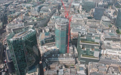
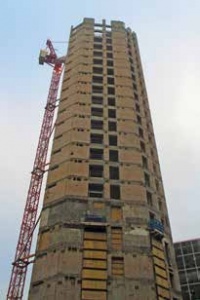
To help gain planning permission for a new office development within a City of London conservation area, a 24-storey concrete-framed building was demolished in 2014, with the exception of its centrally located core, which was retained so that a new structure could be built around it. With the core refurbished and heightened, a new steel-framed office block has risen up on the same spot providing 32,500m2 of floor space - 60% more than was previously available.
Replicating the original structure’s octagonal shape, One Angel Court incorporates two podiums, north and south, both in the same positions as the previous building’s podiums, but at seven storeys high these structures are higher.
According to Mace Project Manager for Structures, Marios Antoniades there are a number of reasons why the new tower and connecting podiums are steel-framed instead of concrete. “Steel has helped us achieve longer spans, have a quicker construction programme, add one additional floor and a double height plant enclosure to the top of the tower, while allowing us to re-use the existing core and foundations.”
Once the demolition of the original concrete frame had been completed the initial steelwork erection programme began in April 2015 with the installation of basement members prior to the reinforced concrete ground floor slab being cast. The double basement of the tower has been reused, as has the single-storey basement in the north podium. To add subterranean floor space and continuity to the scheme, Mace excavated and increased the depth of the south podium basement from one level to two levels.
“We started the main steel erection with the tower as this is on the project’s critical path. Eventually we were working on three fronts once the podiums started,” explains Severfield Senior Project Manager David Managh.
From ground floor up to seventh floor, the tower’s columns are inclined, before straightening up for the upper floors. This means for the uppermost 17 levels, the tower is approximately 3m wider than the original building thereby increasing its available floor space. The tower features 9m clear spans from the centrally positioned core to the perimeter steelwork. Supporting composite metal decking the radial beams are 254UBs, while the perimeter members are slightly larger 525UBs.
Using a refurbished core within the tower presented a challenge for the steel erection. “Each floor had to be thoroughly surveyed prior to the steelwork being installed as the fixing plates were in slightly varying positions on each level because it was important to miss the core’s rebar when they were put in place,” says Mr Managh. “So although the beams are in the same arrangement each floor is slightly different.”
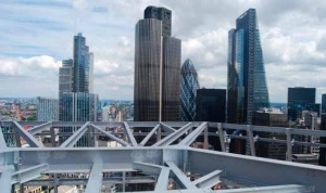
Topping the tower is a steel structure known as the ‘birds’ nest’, which spans the roof plant deck at level 27. To allow construction of this roof and level 26, which is another plant deck, the core was heightened with the addition of a three-storey steel framework. “The original concept for the roof enclosure would have involved a very high piece count, so to speed up the construction schedule the birds’ nest was designed as a light and slender steel frame, stabilised by the core and, importantly, prefabricated offsite in large sections,” says Waterman Regional Director Edwin Bergbaum. Spanning around and over the roof of the tower, the birds’ nest steelwork was prefabricated as a series of galvanized two dimensional trusses measuring 3m-deep and up to 18m-long.
Open-plan office space continues from the tower into the two adjoining podiums, which feature spans of up to 17m-long. While the tower’s beams are shallow UB sections installed to maximise the structure’s floor-to-ceiling heights, the podiums have been formed with a series of Fabsec cellular members erected around slipformed centrally-positioned cores. “With the long spans we wanted to achieve in the podiums, cellular beams were chosen as UB sections of that length would have been too heavy,” says Bergbaum. “As we are reusing the foundations, it was important to make the steel frame as light as possible.”
To aid the construction programme, the podiums perimeter beams and columns were all concrete-encased prior to arriving on site. As the podiums reach a maximum of seven-storeys high, and in order to avert the need to splice the members, the perimeter columns were delivered and erected in lengths of up to 19m, weighing just under 10t each.
The most visually outstanding feature of the podium are the terraces, formed with steps in the steel frame at levels three, four and five, and the rooftop gardens. A series of 11t 500mm-deep fabricated beams was installed throughout both of the podiums to form these terraces.
The main entrance for the scheme is via a double-height space set back along the western elevation. This faces Angel Court, a previously narrow and dark passageway linking Copthall Avenue with Throgmorton Street. According to Fletcher Priest Architects, the development has added 30 per cent to the public realm turning Angel Court into an attractive pedestrian street lined with shops and restaurants, which catch midday sun, rather than a dark alleyway reached through a hole in the wall.
Completion of the project’s shell and core is scheduled for October, and the fit-out is then expected to be finished by the end of this year.
Some of the implications of inclined columns
By Dr Richard Henderson, SCI
The new One Angel Court structure retains the original building footprint but the perimeter columns over the first seven floors are inclined outwards leading to a floor plate that is 3m wider at this level. The next seventeen floors have the same floor plate so the columns above level seven are vertical.
The change in angle of the column at floor seven from inclined to vertical introduces a horizontal force at the intersection point which can be carried as an axial force in the floor beams assuming the intersection point occurs at floor level. The axial force includes permanent and variable components which are coincident with the vertical loads on the beams. The size of the axial forces depends on the slope of the inclined columns and a slope of 1.5m in 30m or 1 in 20 clearly results in a horizontal component which is 5% of the axial force in the column at this level. The axial force could be similar in magnitude to the shear force in the beam.
Tie forces are often specified as equal to the vertical shear force and therefore the axial force would also be similar to the tie force. The notable difference is that, unlike the tie force, the axial force and the shear force are present in the same load case. The normal rules set out in SCI publication P358 Joints in steel construction: Simple joints to Eurocode 3 therefore do not apply to these beam to column joints. Where floor beams connect to the inclined columns on intermediate floors, a small axial component is also developed in the beams due to permanent and variables loads.
In a building with a footprint of a higher degree of rotational symmetry than four (e.g. a hexagon), the horizontal forces at the floor level where the columns become inclined can be resisted as a hoop tension in the perimeter beams with no forces transferred across the building. In a square or rectangular building, the horizontal forces are balanced across the building and would need to be passed through or around the core. If the inclined columns are present on one side of the building only (or if the loads in the columns are not the same on both sides of the building), a net shear force from permanent and variable loads is applied to the building’s lateral load resisting system over the height where the columns are inclined. This shear force is conceptually similar to that resulting from sway imperfections dealt with in BS EN 1993-1-1 clause 5.3.2.
The presence of inclined columns introduces significant additional considerations which are not present in more conventional buildings.
| Architect | Fletcher Priest Architects |
| Structural Engineer | Waterman Structures |
| Steelwork Contractor | Severfield |
| Construction Manager | Mace |
| Main Client | Stanhope/Mitsui Fudosan UK |


