Difference between revisions of "Engineering and Computing Building at Coventry University"
| Line 26: | Line 26: | ||
The steel structure of the Interactive Zone is bolted back to the rest of the building using steel base plates welded to the ends of the sections. "Some of the shear forces produced by the diagonal struts were reasonably large. This necessitated plates measuring typically 500 by 500mm to provide adequate spacing for up to six anchor bolts", explains Pugh. Projecting steel connection plates welded to the outer edge of the beams allow the inner face of the engineered timber facade frame to be bolted to the steel structure with articulation for vertical differential movement. | The steel structure of the Interactive Zone is bolted back to the rest of the building using steel base plates welded to the ends of the sections. "Some of the shear forces produced by the diagonal struts were reasonably large. This necessitated plates measuring typically 500 by 500mm to provide adequate spacing for up to six anchor bolts", explains Pugh. Projecting steel connection plates welded to the outer edge of the beams allow the inner face of the engineered timber facade frame to be bolted to the steel structure with articulation for vertical differential movement. | ||
| − | Autodesk’s [ | + | Autodesk’s [https://www.autodesk.co.uk/products/revit/overview?term=1-YEAR&tab=subscription Revit] software, coupled with [http://www.oasys-software.com/products/engineering/gsa-suite.html Oasys GSA], was used to model and analyse the design, which was then was transferred to [http://www.tekla.com/uk Tekla] software for steelwork contractor Traditional Structures to produce the fabrication model and shop drawings. "We even considered painting the steel sections the same colours as those expressing different axial loads in the General Structural Analysis software contour plot", recalls Pugh, "but the architect felt this would overcomplicate the atrium in visual terms". |
===Fabrication/erection=== | ===Fabrication/erection=== | ||
Revision as of 12:05, 20 November 2023
[top]Article in Architecture Today, Special – Steel Solutions, 30/07/14
Arup Associates’ Engineering & Computing Building (ECB) at Coventry University is a landmark project combining education, industry and research facilities in a single, state-of-the-art building. Rated BREEAM Excellent, the 16,000 square metre scheme includes an engineering centre with flight simulators and engine test cells, a wind tunnel, workshops, lecture theatres, classrooms, interactive communal spaces and offices.
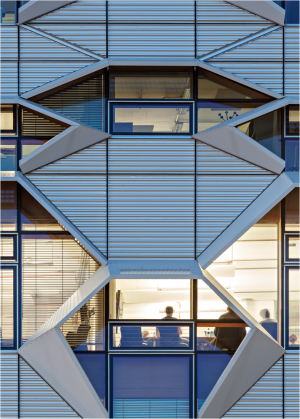
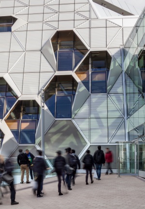
Intended to represent the duality of science and nature, the plan consists of two interlocking L-shaped structures organised around a landscaped courtyard. The three storey Nature block to the south employs a simple glass envelope with an extensive green roof. By contrast, the seven-storey science block to the north has a highly engineered canted façade comprising a lightweight timber frame and aluminium composite cladding panels. Hexagonal windows shaded by projecting aluminium hoods allude to the architect’s concept of a ‘busy colony’.
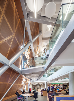
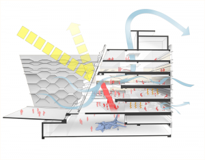
Central to the environmental and spatial concept is the Interactive Zone. This is located behind the inclined ‘shop window’ façade and forms the public and educational heart of the building. Structured using an expressive steel frame, the triple-height space contains the main circulation and breakout spaces, while also providing controlled daylighting and natural ventilation. The flexible, open plan layout is designed to foster collaborative learning and the cross-fertilisation of ideas.
- Facade details
Structural design
Comprising a lattice of horizontal box beams and diagonal CHS struts, the steel structure not only supports a series of pod-like breakout spaces, but also provides lateral restraint for the atrium facade and additional compressive support for the transfer structure at third floor level. "We chose steel because its inherent strength allowed us to create an aesthetically pleasing structure using relatively small sections", says structural engineer Robert Pugh of Arup.
Detail design
The apparently random grid of intersecting and non-intersecting diagonal steel struts is generated both by the desire to avoid running them past the hexagonal window openings, and by the locations within the atrium of the pods, which are of different sizes and have precisely defined geometrical relationships to each other.
Inclined in two directions and varying in diameter from 114mm to 244mm, the circular hollow sections are connected to each other and the horizontal box beams using continuous fillet welds. "We didn’t want the struts to be of uniform size", says Pugh. "Instead, each one corresponds to the structural role it is performing. This is reinforced by printed labels attached to each section, which inform students of the forces acting on the members".
Spanning across the internal face of the inclined atrium facade and corresponding in position to the floor slabs are 450x250mm rectangular hollow sections. These are designed to balance the diagonal forces in the structure (emanating from the struts), and provide lateral bracing for the self-supporting atrium facade. They also serve as edge beams for the breakout pods.
The steel structure of the Interactive Zone is bolted back to the rest of the building using steel base plates welded to the ends of the sections. "Some of the shear forces produced by the diagonal struts were reasonably large. This necessitated plates measuring typically 500 by 500mm to provide adequate spacing for up to six anchor bolts", explains Pugh. Projecting steel connection plates welded to the outer edge of the beams allow the inner face of the engineered timber facade frame to be bolted to the steel structure with articulation for vertical differential movement.
Autodesk’s Revit software, coupled with Oasys GSA, was used to model and analyse the design, which was then was transferred to Tekla software for steelwork contractor Traditional Structures to produce the fabrication model and shop drawings. "We even considered painting the steel sections the same colours as those expressing different axial loads in the General Structural Analysis software contour plot", recalls Pugh, "but the architect felt this would overcomplicate the atrium in visual terms".
[top]Fabrication/erection
The steel sections, including a number of factory-welded components comprising several intersecting elements, were assembled on site using a small mobile crane. Erection took two weeks, after which the frame received an architectural-quality, silver-coloured, thin intumescent coating.
| Architect, Structural and Services Engineer | Arup Associates |
| Steelwork Contractor | Traditional Structures |
| Main Contractor | Vinci Construction |
| Client | Coventry University |


