Difference between revisions of "St Thomas' Hospital East Wing project, London"
| (One intermediate revision by the same user not shown) | |||
| Line 1: | Line 1: | ||
| − | ==Article in [ | + | ==Article in [https://www.newsteelconstruction.com/wp/wp-content/uploads/digi/2014pdf/1405NSCdigi.pdf#page=10 NSC May 2014]== |
{{#image_template:image=File:St_Thomas_East_Wing-1.jpg|align=right|wrap=true|caption=Visualisation of how the reconfigured East Wing will improve the hospital|width=400}} | {{#image_template:image=File:St_Thomas_East_Wing-1.jpg|align=right|wrap=true|caption=Visualisation of how the reconfigured East Wing will improve the hospital|width=400}} | ||
'''Steel cure for hospital'''<br> | '''Steel cure for hospital'''<br> | ||
Latest revision as of 11:31, 11 February 2021
Article in NSC May 2014
Steel cure for hospital
The East Wing building at St Thomas’ Hospital has historically been blighted by water ingress. In order to remedy the situation the structure is being reclad with steel and glass.
By Martin Cooper
Situated on the south bank of the River Thames, facing the Houses of Parliament, St Thomas’ Hospital has been an important London landmark since moving to its present location in 1871. Originally established in the Middle Ages on a site near London Bridge, it has a long and distinguished history and today St Thomas’ is a world renowned teaching hospital.
The appearance of the current site has changed a lot over the years, as many of the original Victorian wards were destroyed during the Second World War and a number of new structures were added in the 1950s and 60s.
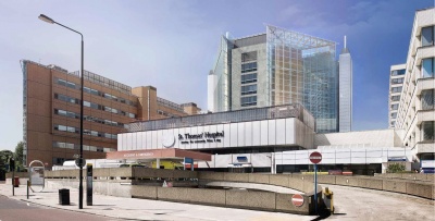
One of these more recent additions is the concrete framed 13-storey East Wing tower, a building opened in the early 1960s and unfortunately blighted by water penetration for most of its lifetime. To solve this building’s structural problem, transform its appearance and improve the functionality a £27M project is under way that will give the tower a new glazed façade, two atria and a new shape.
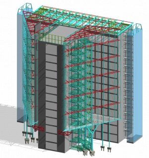
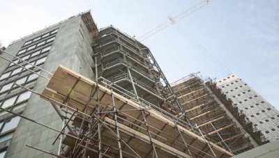
The project includes the installation of new rooftop steelwork that will support glazing on the western façade (overlooking the Houses of Parliament), while further additions of structural steelwork will infill the T-shaped building with two atria creating an on-plan half diamond-shaped structure.
Main contractor ISG’s work also includes restoring the existing building’s exterior slate cladding and teak windows. These elevations will now be essentially interiors, inside the new atria or protected from the elements by the western façade.
Actually getting materials on site has been one of the main challenges for the construction team. Work has been complicated by the fact that the East Wing is located at the heart of the hospital campus, surrounded by other buildings and lacking direct access routes for large deliveries of plant or materials.
The 200-bed capacity building accommodates cardiology services, two intensive care units, admission wards alongside clinical suites and offices, teaching facilities and ancillary plant and storage areas. Throughout the duration of the project all of these facilities have to remain fully operational adding another unique challenge to the construction project.
To overcome the access problem ISG set up a tower crane adjacent to the East Wing to undertake a lot of the lifting, with no room on site for any other cranes.
As far as helping to keep the hospital facilities working as normally as possible ISG has a number of ongoing strategies. Fraser Tanner, ISG Senior Project Manager explains. “We are in constant consultation with the hospital to mitigate potential disruption and communicate with hospital staff on a daily basis to advise when and where we will be working.”
Using structural steelwork for this project has been advantageous as the tower crane can lift most of the elements straight into position so they can be erected immediately upon arrival, and by prefabricating some steel elements the team has reduced the amount of on-site work and the possibility of unwanted noise.
Bourne Steel has fabricated, supplied and erected much of the project’s steelwork, including a prefabricated and modular lift shaft to accommodate two new patients lifts in the eastern atria. “We fabricated, delivered and installed the shaft in two-storey high modules which were light enough for the tower crane to lift into position before they were bolted into place,” explains Kevin Clarke, Bourne Steel Divisional Director.
Prior to installing the lift shaft, Bourne Steel erected the floor steelwork for the two atria. Formed with a series of 600mm × 400mm jumbo box sections they have been installed at second floor level above a triple height basement. Supporting the floors are CHS columns and one feature Y-shaped column at the front that also supports the atria glazing. “The positioning of the columns is very irregular and their installation was one of the biggest challenges due to the amount of services hidden below the site,” explains Christian Dercks, Arup Structural Engineer.
Each of the triangular atria floors cantilevers 2m at the southern tip over low level adjacent buildings. A 1.2m deep truss in each atria supports the cantilevers via bolted connections to the existing East Wing structure. The trusses have to support ten levels of atria and are consequently formed from large 400mm × 400mm box sections.
Forming the outside elevation of the triangular atria are 30m long CHS trusses positioned at every second floor. Brought to site in three sections, these trusses were welded on site before being lifted into place and fixed to the existing building via bolted connections.
The atria roofs will be constructed from ETFE cushions in a rhomboid configuration to shade direct sunlight from the south, while permitting softer indirect light from the north to naturally illuminate the internal space.
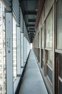
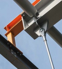
Meanwhile the second steelwork element of the project is the new roof and hanging façade for the west elevation. Bourne Steel has erected a new roof with a series of 15m long rafters that cantilever out by 2.5m. From these rafters a lightweight steel grillage supporting maintenance balconies for each floor is hung via stainless steel tie rods. The front of the grillage is glazed forming a new bright and watertight façade.
Sustainability and environmental performance are also key aspects of the ISG and Hopkins Architects solution, and the re-clad design incorporates a range of passive controls to maintain comfortable ambient temperatures within the building.
Competition kick starts project
The East Wing project was procured via a high profile RIBA competition to select an architect and main contractor team that could transform the poorly performing building with a modern cladding solution to enhance its environmental performance, upgrade facilities for patients and staff, and dramatically improve the building’s aesthetics on the capital’s skyline. The 2010 competition was won by a team comprising of ISG and Hopkins Architects, who have since worked closely with Arup to develop their plans for the building. The team started on site in March 2013 and is expected to complete the work by the end of this year.
Connecting new steelwork to existing concrete structures
By Dr Richard Henderson (SCI)
The process of designing the connections for the new steelwork started with confirming the ability of the existing reinforced concrete structure to carry the additional loads. The original structure of the hospital East Wing was designed in the late 1950s and built in the early 1960s. Archive material included the as-built GAs, sections and reinforcement drawings which showed the bar sizes and position of laps. Cover meter surveys were carried out where fixings to the concrete were to be made to confirm the position of the reinforcement. The results of the surveys generally corresponded with the drawings which therefore proved to be of real value.
The hospital was fully operational during the works so, to accommodate this, most connections were designed to be fixed from the outside. For heavier loads, the connections were designed with fixings bolted through the concrete. The new steel structures at the second floor of the atria involved the transfer of loads of up to 1 MN to the lift shaft and stair well and required through-bolts. Brackets were designed using the existing reinforcement details including an allowance for reinforcement being displaced relative to the nominal position. This strategy proved to be successful in most cases. Where the reinforcement position was not within the allowance, holes were drilled and a template made. A special bracket was then made from the template.
Lighter loads such as those for the west façade were transferred to the existing concrete using face-fixed connections. The arrangement of this type of bracket should be such that adjustment can be made to the position of the bolts to accommodate reinforcement. Brackets can be designed with slotted holes or multiple holes to provide alternative bolt positions.
It is common to percussion-drill holes for new fixings to existing concrete structures instead of using diamond drilling to avoid the risk of cutting reinforcement. If a bar is encountered, it is possible to reposition the hole and re-drill, without having permanently weakened the existing structure.
In general, anchors into existing concrete can either be expanding anchors which apply a bursting force to the concrete or resin anchors which form an adhesive bond inside the hole. Resin anchors can generally be positioned closer together or closer to edges of concrete elements than expanding anchors and still provide their design resistance.
In summary, when designing connections to existing concrete structures: use archive material (if available); carry out a cover-meter survey; use percussion drilling; design brackets with alternative hole positions or slotted holes; use through-bolts for heavier loads; use resin anchors if smaller bolt-groups are required.
| Architect | Hopkins Architects |
| Structural Engineer | Arup |
| Steelwork Contractor | Bourne Steel |
| Main Contractor | ISG |
| Main Client | Guy’s and St Thomas’ NHS Foundation Trust |


