Difference between revisions of "Heron Tower, London"
| (5 intermediate revisions by 2 users not shown) | |||
| Line 1: | Line 1: | ||
{{#image_template:image=File:Heron_Tower_2.png|caption= Heron Tower|align=right|wrap=true|width=400}} | {{#image_template:image=File:Heron_Tower_2.png|caption= Heron Tower|align=right|wrap=true|width=400}} | ||
| − | Heron Tower is a high rise [[Multi-storey_office_buildings|office]] building in the City of London, designed by Kohn Pederson Fox Associates for the property development group Heron International. The building provides over 68000m<sup>2</sup> of floor space, comprising mainly offices with a small amount of retail at the ground and first floors. A restaurant and bar is provided on the 38th to 40th floors, open to members of the public. | + | Heron Tower is a high rise [[Multi-storey_office_buildings|office]] building in the City of London, designed by Kohn Pederson Fox Associates for the property development group Heron International. The building provides over 68000m<sup>2</sup> of floor space, comprising mainly offices with a small amount of retail at the ground and first floors. A restaurant and bar is provided on the 38th to 40th floors, open to members of the public. |
The building is one of the tallest in the City of London. The 47-storey tower rises to 203m in height, with a mast of 39m taking the highest point to 242m. | The building is one of the tallest in the City of London. The 47-storey tower rises to 203m in height, with a mast of 39m taking the highest point to 242m. | ||
| Line 12: | Line 12: | ||
The main superstructure of Heron Tower is a [[Trusses#Vierendeel_trusses|vierendeel]] stress tube that wraps around the perimeter of the office floors. The office floors are supported by long span (up to 14m) solid section Universal [[Steel_construction_products#Standard_open_sections|Beams]] acting [[Composite_construction|compositely]] with a 130mm deep re-entrant [[Steel_construction_products#Decking_for_floors|deck]]. | The main superstructure of Heron Tower is a [[Trusses#Vierendeel_trusses|vierendeel]] stress tube that wraps around the perimeter of the office floors. The office floors are supported by long span (up to 14m) solid section Universal [[Steel_construction_products#Standard_open_sections|Beams]] acting [[Composite_construction|compositely]] with a 130mm deep re-entrant [[Steel_construction_products#Decking_for_floors|deck]]. | ||
| − | The fire engineering practice at [ | + | The fire engineering practice at [https://www.arup.com/expertise/services/buildings/fire Arup] designed an engineered [[Fire_protecting_structural_steelwork|fire protection]] layout, reducing fire protection to all primary members ([[Steel_construction_products#Standard_open_sections|beams and columns]]) from [[Structural_fire_resistance_requirements|2-hours to 90 minutes]] and leaving [[Structural_fire_engineering#Advanced_structural_fire_engineering|secondary beams unprotected]]. This was considered appropriate, because the structural form was developed with close collaboration of the structural engineers and the fire team and deliberately designed to be robust if exposed to a fire event. |
To demonstrate that this would provide an adequate level of protection, a finite element analysis was carried out using the commercial modelling program ABAQUS. | To demonstrate that this would provide an adequate level of protection, a finite element analysis was carried out using the commercial modelling program ABAQUS. | ||
| − | The first stage was to agree a reasonable design base fire scenario. A post- | + | The first stage was to agree a reasonable design base fire scenario. A post-flashover fire on a single level only was proposed as being reasonable. However, due to the atria penetrating the normal floor to floor compartmentation, a multi-storey model with a less severe fire spreading to all floors was also considered and evaluated. |
The models were then created giving a realistic representation of the structure including non-linear temperature dependant material properties, which are necessary to capture the kinds of large displacements seen in structures under fire load. | The models were then created giving a realistic representation of the structure including non-linear temperature dependant material properties, which are necessary to capture the kinds of large displacements seen in structures under fire load. | ||
{{#image_template:image=File:Heron_Tower_3.png| align=left|wrap=true|width=400}} | {{#image_template:image=File:Heron_Tower_3.png| align=left|wrap=true|width=400}} | ||
| − | In the single storey model, with the more severe fire, maximum deflections over unprotected beams were approximately 2m (Span/7.2). By comparison, the [[Structural_fire_engineering#Cardington_fire_tests|Cardington test]] series saw a maximum deflection ratio of approximately Span/10. The response of [[Fire_protecting_structural_steelwork|protected]] primary beams was less with maximum deflections of approximately 500mm (Span/20). The model demonstrated that stability and compartmentation were maintained. The multi-storey model indicated smaller beam deflections (approx. Span/10) due to the less severe but wider spread fire. Even though [[Steel_construction_products#Standard_open_sections|columns]] were affected over a number of floors, there was no indication of instability. A code compliant [[Fire_protecting_structural_steelwork|fire protection]] layout (all beams protected) of the single floor model was also assessed and showed considerable structural movement. It is commonly assumed that a building designed to code requirements will be relatively unaffected by fire. This analysis demonstrated that large deflections will occur in fully protected buildings in a post- | + | In the single storey model, with the more severe fire, maximum deflections over unprotected beams were approximately 2m (Span/7.2). By comparison, the [[Structural_fire_engineering#Cardington_fire_tests|Cardington test]] series saw a maximum deflection ratio of approximately Span/10. The response of [[Fire_protecting_structural_steelwork|protected]] primary beams was less with maximum deflections of approximately 500mm (Span/20). The model demonstrated that stability and compartmentation were maintained. The multi-storey model indicated smaller beam deflections (approx. Span/10) due to the less severe but wider spread fire. Even though [[Steel_construction_products#Standard_open_sections|columns]] were affected over a number of floors, there was no indication of instability. A code compliant [[Fire_protecting_structural_steelwork|fire protection]] layout (all beams protected) of the single floor model was also assessed and showed considerable structural movement. It is commonly assumed that a building designed to code requirements will be relatively unaffected by fire. This analysis demonstrated that large deflections will occur in fully protected buildings in a post-flashover fire. The finite element analysis also allowed [https://www.arup.com/expertise/services/buildings/fire Arup Fire] to demonstrate the forces/stresses and strains in the building and show that stability is achieved. |
Approval was granted in December 2006, achieving significant savings for the client, not only in terms of the cost and the consequential reduction in required future maintenance, but also the benefit to the project program and better architectural finishes to exposed elements. Additionally, by reducing the amount of spray-on [[Fire_protecting_structural_steelwork#Thin_film_intumescent_coatings|intumescent]] the environmental impact of the building and hazard to workers was reduced. | Approval was granted in December 2006, achieving significant savings for the client, not only in terms of the cost and the consequential reduction in required future maintenance, but also the benefit to the project program and better architectural finishes to exposed elements. Additionally, by reducing the amount of spray-on [[Fire_protecting_structural_steelwork#Thin_film_intumescent_coatings|intumescent]] the environmental impact of the building and hazard to workers was reduced. | ||
| Line 30: | Line 30: | ||
The British Standards recommend that a smoke reservoir be provided in the top of the atrium to delay the time it takes for the smoke layer to build down to a level where it could spread back onto the upper floors and hence potentially affect escape. In this case, in order to create a suitable reservoir, it would have been necessary to separate the uppermost level of the atrium with smoke retarding construction. | The British Standards recommend that a smoke reservoir be provided in the top of the atrium to delay the time it takes for the smoke layer to build down to a level where it could spread back onto the upper floors and hence potentially affect escape. In this case, in order to create a suitable reservoir, it would have been necessary to separate the uppermost level of the atrium with smoke retarding construction. | ||
| − | However, to achieve the flexibility of open or enclosed atria desired by the client, | + | However, to achieve the flexibility of open or enclosed atria desired by the client, Computational Fluid Dynamics (CFD) modelling was undertaken to demonstrate that occupant evacuation at the upper levels would not be compromised by the smoke spreading from a fire at one of the lower levels via the open sided atria. |
{{#image_template:image=File:HeronTower_5.png|align=left|wrap=true|width=400}} | {{#image_template:image=File:HeronTower_5.png|align=left|wrap=true|width=400}} | ||
| − | The | + | The CFD analysis was run in two parts. The first model was created to assess the conditions that occupants of the top floor of a village may face as a result of smoke spreading via the atrium from a fire on a lower floor. An axi-symmetric plume in the base of the atrium and a spill plume from the lowest level were modelled. It was demonstrated that for both scenarios, occupants would have adequate time to evacuate away from the atrium and into cores before the onset of untenable conditions due to visibility, temperature and carbon monoxide levels. |
{{#image_template:image=File:Heron_Tower_6.png|align=left|wrap=true|width=400}} | {{#image_template:image=File:Heron_Tower_6.png|align=left|wrap=true|width=400}} | ||
The second model was created to assess the conditions occupants might face on a single floor of the building if there was no atrium, i.e. a possible ‘code compliant’ arrangement. The results of this analysis demonstrated that conditions would be significantly better in the proposed village arrangement with an atrium when compared to a single storey arrangement without an atrium. | The second model was created to assess the conditions occupants might face on a single floor of the building if there was no atrium, i.e. a possible ‘code compliant’ arrangement. The results of this analysis demonstrated that conditions would be significantly better in the proposed village arrangement with an atrium when compared to a single storey arrangement without an atrium. | ||
| Line 38: | Line 38: | ||
It was therefore demonstrated that the village concept would not compromise occupant life safety due to smoke spread, and that the design performed better than a possible code compliant arrangement. | It was therefore demonstrated that the village concept would not compromise occupant life safety due to smoke spread, and that the design performed better than a possible code compliant arrangement. | ||
| − | {|class="wikitable" width= | + | {|class="wikitable" width=500 |
|- | |- | ||
|'''Architect'''||Kohn Pederson Fox Associates | |'''Architect'''||Kohn Pederson Fox Associates | ||
| Line 51: | Line 51: | ||
|} | |} | ||
| − | [[Category:Case studies | + | [[Category:Case studies - Structural fire engineering]] |
Latest revision as of 13:10, 22 April 2020
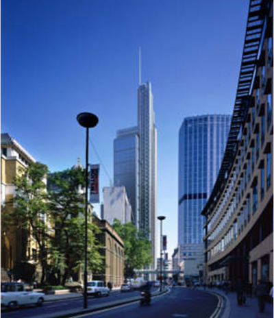
Heron Tower is a high rise office building in the City of London, designed by Kohn Pederson Fox Associates for the property development group Heron International. The building provides over 68000m2 of floor space, comprising mainly offices with a small amount of retail at the ground and first floors. A restaurant and bar is provided on the 38th to 40th floors, open to members of the public.
The building is one of the tallest in the City of London. The 47-storey tower rises to 203m in height, with a mast of 39m taking the highest point to 242m.
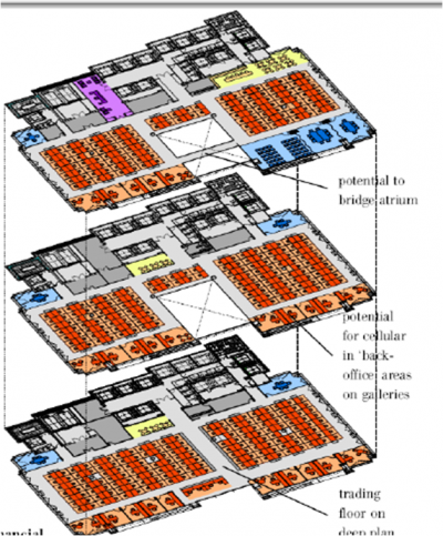
A key requirement of the architectural design was to maintain an open, interconnected feel to the building. This has been achieved by sub-dividing the tower into ten 3-storey villages, each with accommodation arranged around a central atrium.
Each 3-storey village is separated from the next by a 2-hour fire rated compartment floor, hence the principle behind the fire safety design is to treat each village as a 3-storey building connected by an open void. This leads to the requirement to assess multi-storey fires as part of the general fire safety strategy and for the structural fire protection of the building.
The building is also split vertically into two zones, with the accommodation and atria situated to the north of the building and the core zone containing combined fire fighting / escape stairs and plant rooms situated to the south.
The main superstructure of Heron Tower is a vierendeel stress tube that wraps around the perimeter of the office floors. The office floors are supported by long span (up to 14m) solid section Universal Beams acting compositely with a 130mm deep re-entrant deck.
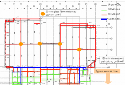
The fire engineering practice at Arup designed an engineered fire protection layout, reducing fire protection to all primary members (beams and columns) from 2-hours to 90 minutes and leaving secondary beams unprotected. This was considered appropriate, because the structural form was developed with close collaboration of the structural engineers and the fire team and deliberately designed to be robust if exposed to a fire event.
To demonstrate that this would provide an adequate level of protection, a finite element analysis was carried out using the commercial modelling program ABAQUS.
The first stage was to agree a reasonable design base fire scenario. A post-flashover fire on a single level only was proposed as being reasonable. However, due to the atria penetrating the normal floor to floor compartmentation, a multi-storey model with a less severe fire spreading to all floors was also considered and evaluated.
The models were then created giving a realistic representation of the structure including non-linear temperature dependant material properties, which are necessary to capture the kinds of large displacements seen in structures under fire load.
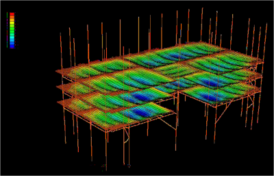
In the single storey model, with the more severe fire, maximum deflections over unprotected beams were approximately 2m (Span/7.2). By comparison, the Cardington test series saw a maximum deflection ratio of approximately Span/10. The response of protected primary beams was less with maximum deflections of approximately 500mm (Span/20). The model demonstrated that stability and compartmentation were maintained. The multi-storey model indicated smaller beam deflections (approx. Span/10) due to the less severe but wider spread fire. Even though columns were affected over a number of floors, there was no indication of instability. A code compliant fire protection layout (all beams protected) of the single floor model was also assessed and showed considerable structural movement. It is commonly assumed that a building designed to code requirements will be relatively unaffected by fire. This analysis demonstrated that large deflections will occur in fully protected buildings in a post-flashover fire. The finite element analysis also allowed Arup Fire to demonstrate the forces/stresses and strains in the building and show that stability is achieved.
Approval was granted in December 2006, achieving significant savings for the client, not only in terms of the cost and the consequential reduction in required future maintenance, but also the benefit to the project program and better architectural finishes to exposed elements. Additionally, by reducing the amount of spray-on intumescent the environmental impact of the building and hazard to workers was reduced.
This is understood to have been the first building in the UK that was been approved using a multi-storey fire analysis as a fundamental part of the approvals process and is now widely seen as a benchmark for structural fire engineering in London.
To increase the lettability, the client wanted complete flexibility of the villages to allow tenants to either enclose the atria or leave them open to the accommodation. Because open atria would introduce a direct route for smoke to spread between levels, the fire safety design was developed using a simultaneous evacuation regime within each village, and ensuring that occupants on all parts of the floors can always escape away from the atrium in order to reach the escape cores.
The British Standards recommend that a smoke reservoir be provided in the top of the atrium to delay the time it takes for the smoke layer to build down to a level where it could spread back onto the upper floors and hence potentially affect escape. In this case, in order to create a suitable reservoir, it would have been necessary to separate the uppermost level of the atrium with smoke retarding construction.
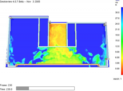
However, to achieve the flexibility of open or enclosed atria desired by the client, Computational Fluid Dynamics (CFD) modelling was undertaken to demonstrate that occupant evacuation at the upper levels would not be compromised by the smoke spreading from a fire at one of the lower levels via the open sided atria.
The CFD analysis was run in two parts. The first model was created to assess the conditions that occupants of the top floor of a village may face as a result of smoke spreading via the atrium from a fire on a lower floor. An axi-symmetric plume in the base of the atrium and a spill plume from the lowest level were modelled. It was demonstrated that for both scenarios, occupants would have adequate time to evacuate away from the atrium and into cores before the onset of untenable conditions due to visibility, temperature and carbon monoxide levels.
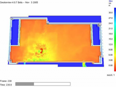
The second model was created to assess the conditions occupants might face on a single floor of the building if there was no atrium, i.e. a possible ‘code compliant’ arrangement. The results of this analysis demonstrated that conditions would be significantly better in the proposed village arrangement with an atrium when compared to a single storey arrangement without an atrium.
It was therefore demonstrated that the village concept would not compromise occupant life safety due to smoke spread, and that the design performed better than a possible code compliant arrangement.
| Architect | Kohn Pederson Fox Associates |
| Steelwork Contractor | Severfield-Rowen (now Severfield (UK) Ltd) |
| Main Contractor | Skanska |
| Developer | Heron International |
| Structural and fire engineering | Arup (Arup Fire) |


