Difference between revisions of "Clyde Arch Bridge, Glasgow"
(Created page with "==Structural Steel Design Awards 2007 - Winner== {{#image_template:image=File:Clyde_arc_bridge.png|align=right|wrap=true|width=400}} This new [...") |
|||
| (3 intermediate revisions by 2 users not shown) | |||
| Line 3: | Line 3: | ||
This new [[Sustainable_steel_bridges#Aesthetically pleasing bridges|landmark bridge]], known as the 'Clyde Arc Bridge', crosses the River Clyde in Glasgow and significantly improves access to Pacific Quay Area and is a major catalyst in the redevelopment of this once derelict site. | This new [[Sustainable_steel_bridges#Aesthetically pleasing bridges|landmark bridge]], known as the 'Clyde Arc Bridge', crosses the River Clyde in Glasgow and significantly improves access to Pacific Quay Area and is a major catalyst in the redevelopment of this once derelict site. | ||
| − | The 96m span single arch rib and the [[Tied-arch_bridges#Hangers|hangers]] are a prominent yet complementary feature in the surrounding environment. The single arch rib straddling the deck is the first such structure in the UK to be [[Tied-arch_bridges|tied to the deck]]. The diamond shaped arch section is also unique. | + | The 96m span single arch rib and the [[Tied-arch_bridges#Hangers|hangers]] are a prominent yet complementary feature in the surrounding environment. The single arch rib straddling the [[Ladder_deck_composite_bridges|deck]] is the first such structure in the UK to be [[Tied-arch_bridges|tied to the deck]]. The diamond shaped arch section is also unique. |
A condition that arose from the planning consent process was that the [[Bridges|bridge]] should incorporate provision for a light rapid transit tram system in addition to the four lanes of traffic. This included increasing the surfacing on the bridge to 230mm to accommodate standard tram rails and the reconfiguration of the [[Bridge_articulation_and_bearing_specification#Articulation|bridge articulation]] by moving the [[Bridge_articulation_and_bearing_specification#Expansion joints|expansion joints]] from the abutments to the piers. These changes had fundamental implications for the design of the structure in that increasing the dead and live loading and reducing the relative stiffness of the deck significantly increased the load carried by the [[Tied-arch_bridges#Hangers|hangers]] and arch. However these changes were readily accommodated without changing the original [[Bridges_-_initial_design|design concept]]. | A condition that arose from the planning consent process was that the [[Bridges|bridge]] should incorporate provision for a light rapid transit tram system in addition to the four lanes of traffic. This included increasing the surfacing on the bridge to 230mm to accommodate standard tram rails and the reconfiguration of the [[Bridge_articulation_and_bearing_specification#Articulation|bridge articulation]] by moving the [[Bridge_articulation_and_bearing_specification#Expansion joints|expansion joints]] from the abutments to the piers. These changes had fundamental implications for the design of the structure in that increasing the dead and live loading and reducing the relative stiffness of the deck significantly increased the load carried by the [[Tied-arch_bridges#Hangers|hangers]] and arch. However these changes were readily accommodated without changing the original [[Bridges_-_initial_design|design concept]]. | ||
| Line 9: | Line 9: | ||
[[Sustainable_steel_bridges#Environmental priorities|Minimising the environmental impact]] was a key factor in the development of the conceptual and detailed design. This included the use of tubular piles and pre-cast concrete set above river bed level to minimise disturbing riverbed sediments. Maximising the use of [[Design_for_steel_bridge_construction#Fabricating the steelwork|off-site prefabrication]] in terms of steel and pre-cast concrete also minimised the duration of on-site works and significantly reduced the possibility of concrete spillage. | [[Sustainable_steel_bridges#Environmental priorities|Minimising the environmental impact]] was a key factor in the development of the conceptual and detailed design. This included the use of tubular piles and pre-cast concrete set above river bed level to minimise disturbing riverbed sediments. Maximising the use of [[Design_for_steel_bridge_construction#Fabricating the steelwork|off-site prefabrication]] in terms of steel and pre-cast concrete also minimised the duration of on-site works and significantly reduced the possibility of concrete spillage. | ||
| − | The solution offered in response to the client's brief is a [[Tied-arch_bridges|bowstring arch]] with a single arch rib straddling the deck and inclined [[Tied-arch_bridges#Hangers|hangers]] connected to outriggers on the edge of the deck which creates interest for users of the bridge in terms of driving through the arch and [[Tied-arch_bridges#Hangers|hanger]]. The single arch also clearly expresses the structural principles of the bridge and is not confused by a second arch rib or [[Tied-arch_bridges#Components and choice of materials|bracing members]]. | + | The solution offered in response to the client's brief is a [[Tied-arch_bridges|bowstring arch]] with a single arch rib straddling the [[Ladder_deck_composite_bridges|deck]] and inclined [[Tied-arch_bridges#Hangers|hangers]] connected to outriggers on the edge of the deck which creates interest for users of the bridge in terms of driving through the arch and [[Tied-arch_bridges#Hangers|hanger]]. The single arch also clearly expresses the structural principles of the bridge and is not confused by a second arch rib or [[Tied-arch_bridges#Components and choice of materials|bracing members]]. |
The diamond shaped [[Tied-arch_bridges#Components and choice of materials|arch rib]] is a unique feature of the bridge and significantly enhances the slenderness of the arch while also providing significant visual interest from the constantly changing reflection of sunlight and from the projection of the architectural lighting. | The diamond shaped [[Tied-arch_bridges#Components and choice of materials|arch rib]] is a unique feature of the bridge and significantly enhances the slenderness of the arch while also providing significant visual interest from the constantly changing reflection of sunlight and from the projection of the architectural lighting. | ||
| Line 17: | Line 17: | ||
The arch is 130 metres long around the curve and was [[Tied-arch_bridges#Fabrication|fabricated]] in sections each weighing approximately 50 tonnes. The [[Tied-arch_bridges#Fabrication|fabrication]] was difficult due to the doubly curved nature of the side plates. A [[Design_for_steel_bridge_construction#Modelling the structure|3-dimensional model]] was used to produce the fabrication jig that was set up accurately on the shop floor using XYZ coordinates. The individual [[Steel_construction_products#Flat products - plates|plates]] that had been accurately [[Design_for_steel_bridge_construction#Cutting_.26_drilling|pre-cut]] were fitted into the jig and the components tack welded together. The arch sections were then lifted out of the assembly jig with specially designed carrying and turning frames that allowed the sections to be rotated so that the [[Design_for_steel_bridge_construction#Welding|longitudinal seam welds]] could be placed in a down hand position. | The arch is 130 metres long around the curve and was [[Tied-arch_bridges#Fabrication|fabricated]] in sections each weighing approximately 50 tonnes. The [[Tied-arch_bridges#Fabrication|fabrication]] was difficult due to the doubly curved nature of the side plates. A [[Design_for_steel_bridge_construction#Modelling the structure|3-dimensional model]] was used to produce the fabrication jig that was set up accurately on the shop floor using XYZ coordinates. The individual [[Steel_construction_products#Flat products - plates|plates]] that had been accurately [[Design_for_steel_bridge_construction#Cutting_.26_drilling|pre-cut]] were fitted into the jig and the components tack welded together. The arch sections were then lifted out of the assembly jig with specially designed carrying and turning frames that allowed the sections to be rotated so that the [[Design_for_steel_bridge_construction#Welding|longitudinal seam welds]] could be placed in a down hand position. | ||
| − | The construction of the abutments, piles, composite deck and steelwork were totally integrated resulting in efficiencies and cost savings. For example a large floating [[Design_for_steel_bridge_construction#Erection using cranes|crane]] was required for the installation of the steel piles and the steel deck girders and pre-cast units were sized around the lifting capacity of this [[Design_for_steel_bridge_construction#Erection using cranes|crane]]. | + | The construction of the abutments, piles, [[Ladder_deck_composite_bridges|composite deck]] and steelwork were totally integrated resulting in efficiencies and cost savings. For example a large floating [[Design_for_steel_bridge_construction#Erection using cranes|crane]] was required for the installation of the steel piles and the steel deck girders and pre-cast units were sized around the lifting capacity of this [[Design_for_steel_bridge_construction#Erection using cranes|crane]]. |
{{#image_template:image=File:Clyde_Arc-2.jpg|align=right|wrap=true|width=300}} | {{#image_template:image=File:Clyde_Arc-2.jpg|align=right|wrap=true|width=300}} | ||
| − | Four temporary trestles were installed in the river to support the deck during construction. Every lift was planned in detail and, in order to save hook time on the expensive floating [[Design_for_steel_bridge_construction#Erection using cranes|crane]], a hinged detail was developed so that all the [[Design_for_steel_bridge_construction#Bolting|splice plates]] could be fixed to the beams on the shore with a small [[Design_for_steel_bridge_construction#Erection using cranes|crane]] and, once in position, the [[Design_for_steel_bridge_construction#Bolting|splice plates]] could be manually swung into place by the erectors. The steelwork erectors also placed the large full depth pre-cast concrete deck units using the same [[Design_for_steel_bridge_construction#Erection using cranes|crane]]. | + | Four temporary trestles were installed in the river to support the [[Ladder_deck_composite_bridges|deck]] during construction. Every lift was planned in detail and, in order to save hook time on the expensive floating [[Design_for_steel_bridge_construction#Erection using cranes|crane]], a hinged detail was developed so that all the [[Design_for_steel_bridge_construction#Bolting|splice plates]] could be fixed to the beams on the shore with a small [[Design_for_steel_bridge_construction#Erection using cranes|crane]] and, once in position, the [[Design_for_steel_bridge_construction#Bolting|splice plates]] could be manually swung into place by the erectors. The steelwork erectors also placed the large full depth pre-cast concrete deck units using the same [[Design_for_steel_bridge_construction#Erection using cranes|crane]]. |
The nine arch pieces were [[Design_for_steel_bridge_construction#Transportation|delivered]], assembled and [[Design_for_steel_bridge_construction#Welding|welded]] on the deck into three large sections each weighing 150 tonnes. Two 500 tonne capacity [[Design_for_steel_bridge_construction#Erection using cranes|cranes]] were then used to tandem lift the three sections onto the temporary trestles. The support trestles were then de-jacked and removed and the [[Tied-arch_bridges#Hangers|hangers]] installed. Finally the deck weight was transferred to the [[Tied-arch_bridges#Hangers|hangers]] and arch and the temporary supports in the river removed. The whole of the superstructure was completed between November 2005 and June 2006. | The nine arch pieces were [[Design_for_steel_bridge_construction#Transportation|delivered]], assembled and [[Design_for_steel_bridge_construction#Welding|welded]] on the deck into three large sections each weighing 150 tonnes. Two 500 tonne capacity [[Design_for_steel_bridge_construction#Erection using cranes|cranes]] were then used to tandem lift the three sections onto the temporary trestles. The support trestles were then de-jacked and removed and the [[Tied-arch_bridges#Hangers|hangers]] installed. Finally the deck weight was transferred to the [[Tied-arch_bridges#Hangers|hangers]] and arch and the temporary supports in the river removed. The whole of the superstructure was completed between November 2005 and June 2006. | ||
| Line 31: | Line 31: | ||
|'''Structural Engineer'''||Halcrow | |'''Structural Engineer'''||Halcrow | ||
|- | |- | ||
| − | |'''Steelwork Contractor'''||Watson Steel Structures Ltd. | + | |'''Steelwork Contractor'''||Watson Steel Structures Ltd. <br>(now Severfield (UK) Ltd) |
|- | |- | ||
|'''Main Contractor'''||Edmund Nuttall | |'''Main Contractor'''||Edmund Nuttall | ||
| Line 45: | Line 45: | ||
This landmark structure is thoroughly professional, meets the aspirations of the client and is a major addition to the skyline of Glasgow. | This landmark structure is thoroughly professional, meets the aspirations of the client and is a major addition to the skyline of Glasgow. | ||
| − | [[Category:Case studies | + | [[Category:Case studies - Bridges]] |
Latest revision as of 12:16, 12 March 2019
Structural Steel Design Awards 2007 - Winner
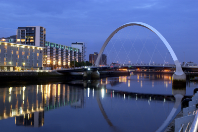
This new landmark bridge, known as the 'Clyde Arc Bridge', crosses the River Clyde in Glasgow and significantly improves access to Pacific Quay Area and is a major catalyst in the redevelopment of this once derelict site.
The 96m span single arch rib and the hangers are a prominent yet complementary feature in the surrounding environment. The single arch rib straddling the deck is the first such structure in the UK to be tied to the deck. The diamond shaped arch section is also unique.
A condition that arose from the planning consent process was that the bridge should incorporate provision for a light rapid transit tram system in addition to the four lanes of traffic. This included increasing the surfacing on the bridge to 230mm to accommodate standard tram rails and the reconfiguration of the bridge articulation by moving the expansion joints from the abutments to the piers. These changes had fundamental implications for the design of the structure in that increasing the dead and live loading and reducing the relative stiffness of the deck significantly increased the load carried by the hangers and arch. However these changes were readily accommodated without changing the original design concept.
Minimising the environmental impact was a key factor in the development of the conceptual and detailed design. This included the use of tubular piles and pre-cast concrete set above river bed level to minimise disturbing riverbed sediments. Maximising the use of off-site prefabrication in terms of steel and pre-cast concrete also minimised the duration of on-site works and significantly reduced the possibility of concrete spillage.
The solution offered in response to the client's brief is a bowstring arch with a single arch rib straddling the deck and inclined hangers connected to outriggers on the edge of the deck which creates interest for users of the bridge in terms of driving through the arch and hanger. The single arch also clearly expresses the structural principles of the bridge and is not confused by a second arch rib or bracing members.
The diamond shaped arch rib is a unique feature of the bridge and significantly enhances the slenderness of the arch while also providing significant visual interest from the constantly changing reflection of sunlight and from the projection of the architectural lighting.
The structural relevance of the diamond shape is also demonstrated by the fact that in cross section the hangers intersect the arch rib at angles approaching 90 degrees. The arch springings are also a unique architectural feature of the structure with the transition from the steel diamond shape to a square concrete section which tapers out and when intersecting with the circular piers results in the interesting scallop features. Other key architectural features include the two platforms that provide a vantage point for viewing the river and surrounding environment and the architectural lighting.
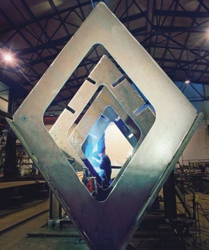
The arch is 130 metres long around the curve and was fabricated in sections each weighing approximately 50 tonnes. The fabrication was difficult due to the doubly curved nature of the side plates. A 3-dimensional model was used to produce the fabrication jig that was set up accurately on the shop floor using XYZ coordinates. The individual plates that had been accurately pre-cut were fitted into the jig and the components tack welded together. The arch sections were then lifted out of the assembly jig with specially designed carrying and turning frames that allowed the sections to be rotated so that the longitudinal seam welds could be placed in a down hand position.
The construction of the abutments, piles, composite deck and steelwork were totally integrated resulting in efficiencies and cost savings. For example a large floating crane was required for the installation of the steel piles and the steel deck girders and pre-cast units were sized around the lifting capacity of this crane.
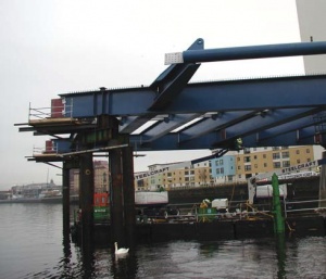
Four temporary trestles were installed in the river to support the deck during construction. Every lift was planned in detail and, in order to save hook time on the expensive floating crane, a hinged detail was developed so that all the splice plates could be fixed to the beams on the shore with a small crane and, once in position, the splice plates could be manually swung into place by the erectors. The steelwork erectors also placed the large full depth pre-cast concrete deck units using the same crane.
The nine arch pieces were delivered, assembled and welded on the deck into three large sections each weighing 150 tonnes. Two 500 tonne capacity cranes were then used to tandem lift the three sections onto the temporary trestles. The support trestles were then de-jacked and removed and the hangers installed. Finally the deck weight was transferred to the hangers and arch and the temporary supports in the river removed. The whole of the superstructure was completed between November 2005 and June 2006.
This impressive bridge meets all the client's aspirations and was completed to programme within budget. It is an excellent example of the benefits that early contractor involvement, associated with an integrated design team, can bring to a project.
| Architect | Gillespies Architects |
| Structural Engineer | Halcrow |
| Steelwork Contractor | Watson Steel Structures Ltd. (now Severfield (UK) Ltd) |
| Main Contractor | Edmund Nuttall |
| Client | Glasgow City Council |
Judges' comments
The new bridge provides strategic access to the Pacific Quay area, and is already a strong catalyst for redevelopment of this once derelict part of the city.
The single arch has a diamond-shaped profile, giving a slender appearance enhanced by reflections of light from the sky and the river surface, strikingly augmented at night by architectural illumination. The design of the arch, the hangers and deck, is satisfyingly and effectively resolved with clear expression of their functions.
This landmark structure is thoroughly professional, meets the aspirations of the client and is a major addition to the skyline of Glasgow.


