Difference between revisions of "Acoustic performance of floors"
| (5 intermediate revisions by the same user not shown) | |||
| Line 2: | Line 2: | ||
This article presents construction solutions for separating and [[Acoustic_performance_of_floors#Internal_floors|internal floors]], together with [[Acoustic_performance_of_floors#Floor_treatments|treatments for floors]] and [[Acoustic_performance_of_floors#Ceiling_treatments|ceilings]] to achieve various levels of acoustic performance. There is a wide range of possible [[#Separating floors|separating floor constructions]], due to the permutations of type of [[Acoustic_performance_of_floors#Floor_treatments|floor treatment]], [[Acoustic_performance_of_floors#Ceiling_treatments|ceiling]], quilt and [[Floor systems|structural solution]] that may be used. The floors systems shown therefore are only a sample of the possible [[#Separating floors|separating floors]] that can be used with steel construction. | This article presents construction solutions for separating and [[Acoustic_performance_of_floors#Internal_floors|internal floors]], together with [[Acoustic_performance_of_floors#Floor_treatments|treatments for floors]] and [[Acoustic_performance_of_floors#Ceiling_treatments|ceilings]] to achieve various levels of acoustic performance. There is a wide range of possible [[#Separating floors|separating floor constructions]], due to the permutations of type of [[Acoustic_performance_of_floors#Floor_treatments|floor treatment]], [[Acoustic_performance_of_floors#Ceiling_treatments|ceiling]], quilt and [[Floor systems|structural solution]] that may be used. The floors systems shown therefore are only a sample of the possible [[#Separating floors|separating floors]] that can be used with steel construction. | ||
| − | The SCI has developed an [[#Resources|acoustic performance prediction tool]] for separating walls to assist designers and architects. | + | The SCI has developed an [[#Resources|acoustic performance prediction tool]] for separating floors and walls to assist designers and architects. |
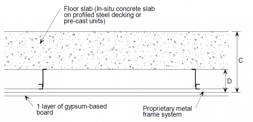
{{#image_template:image=File:F4_18.png|caption=Metal frame system|align=right|wrap=true|width=500}} | {{#image_template:image=File:F4_18.png|caption=Metal frame system|align=right|wrap=true|width=500}} | ||
| Line 16: | Line 16: | ||
'''Structural floor ''' | '''Structural floor ''' | ||
| − | A [[Floor_systems#Composite_slabs|composite floor slab]] consisting of in-situ normal weight concrete and [[Steel_construction_products#Decking_for_floors|steel decking]] supported on steel beams. The steel beams may be below the composite slab (as shown) or integrated into the depth of the slab. The [[Steel_construction_products#Decking_for_floors|decking]] may be ‘shallow’ or ‘deep’, re-entrant or trapezoidal. Typically, the concrete thickness is at least 80 mm at the shallowest point and at least 130 mm at the deepest point. This floor is a Robust Detail (E-FS-1) when specified to comply with the requirements given in the | + | A [[Floor_systems#Composite_slabs|composite floor slab]] consisting of in-situ normal weight concrete and [[Steel_construction_products#Decking_for_floors|steel decking]] supported on steel beams. The steel beams may be below the composite slab (as shown) or integrated into the depth of the slab. The [[Steel_construction_products#Decking_for_floors|decking]] may be ‘shallow’ or ‘deep’, re-entrant or trapezoidal. Typically, the concrete thickness is at least 80 mm at the shallowest point and at least 130 mm at the deepest point. This floor is a Robust Detail (E-FS-1) when specified to comply with the requirements given in the Robust Details Handbook<ref name="No1">[https://www.robustdetails.com/ Robust Details Handbook, Robust Details Limited, 2014.]</ref>. |
'''[[Acoustic_performance_of_floors#Ceiling_treatments|Ceiling]]''' | '''[[Acoustic_performance_of_floors#Ceiling_treatments|Ceiling]]''' | ||
| Line 66: | Line 66: | ||
'''Structural floor''' | '''Structural floor''' | ||
| − | [[Steel_construction_products#.27Light_steel.27_sections|Light steel joists]] at 400 to 600 mm centres. The [[Steel_construction_products#.27Light_steel.27_sections|light steel joists]] are generally 150 to 250 mm deep ‘C’ sections. A decking board is fixed to the top of the joists; the decking board may be chipboard, OSB or plywood. The thickness of a chipboard or OSB decking board is typically 18 to 22 mm; a plywood decking board is typically 9 to 15 mm. A resilient isolation tape can be applied to the top of the [[Steel_construction_products#.27Light_steel.27_sections|light steel joists]] to improve impact sound insulation. This floor is a Robust Detail (E-FS-2) when specified to comply with the requirements given in the | + | [[Steel_construction_products#.27Light_steel.27_sections|Light steel joists]] at 400 to 600 mm centres. The [[Steel_construction_products#.27Light_steel.27_sections|light steel joists]] are generally 150 to 250 mm deep ‘C’ sections. A decking board is fixed to the top of the joists; the decking board may be chipboard, OSB or plywood. The thickness of a chipboard or OSB decking board is typically 18 to 22 mm; a plywood decking board is typically 9 to 15 mm. A resilient isolation tape can be applied to the top of the [[Steel_construction_products#.27Light_steel.27_sections|light steel joists]] to improve impact sound insulation. This floor is a Robust Detail (E-FS-2) when specified to comply with the requirements given in the Robust Details Handbook<ref name="No1"></ref> |
'''[[Acoustic_performance_of_floors#Ceiling_treatments|Ceiling]]''' | '''[[Acoustic_performance_of_floors#Ceiling_treatments|Ceiling]]''' | ||
| Line 415: | Line 415: | ||
*M.W. Simons & J. R. Waters. Sound Control in Buildings. A guide to Part E of the Building Regulations. Blackwell publishing, 2004. | *M.W. Simons & J. R. Waters. Sound Control in Buildings. A guide to Part E of the Building Regulations. Blackwell publishing, 2004. | ||
*[http://mcrma.co.uk/wp-content/uploads/2015/08/MCRMA-TP8.pdf Technical paper No. 8. Acoustic Guide for Metal Roof and Wall Cladding Systems, MCRMA] | *[http://mcrma.co.uk/wp-content/uploads/2015/08/MCRMA-TP8.pdf Technical paper No. 8. Acoustic Guide for Metal Roof and Wall Cladding Systems, MCRMA] | ||
| − | *BS EN ISO 10140: | + | *BS EN ISO 10140: 2021 Acoustics. Laboratory measurement of sound insulation of building elements. Various parts. British Standards Institution. |
==Resources== | ==Resources== | ||
Latest revision as of 14:42, 16 September 2022
This article presents construction solutions for separating and internal floors, together with treatments for floors and ceilings to achieve various levels of acoustic performance. There is a wide range of possible separating floor constructions, due to the permutations of type of floor treatment, ceiling, quilt and structural solution that may be used. The floors systems shown therefore are only a sample of the possible separating floors that can be used with steel construction.
The SCI has developed an acoustic performance prediction tool for separating floors and walls to assist designers and architects.
[top]Separating floors
There is a wide range of possible separating floor constructions, due to the permutations of type of floor treatment, ceiling, quilt and structural solution that may be used. The floors systems shown therefore are only a sample of the possible separating floors that can be used with steel construction.
All expected acoustic performance values are indicative and provided that the floors are built correctly and their junctions are properly detailed and integrated with other elements, these examples should provide the quoted expected acoustic performance. Manufacturers’ literature, system suppliers and/or an acoustic consultant should be consulted for detailed specifications and more precise expected acoustic performance figures.
More detailed guidance on the acoustic detailing of precast units supported on steel beams is provided in SCI P351.
[top]Composite floor on steel beams
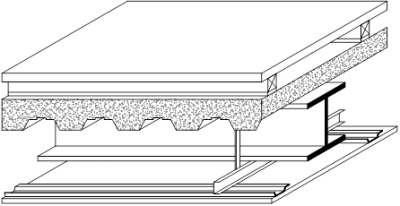
Structural floor
A composite floor slab consisting of in-situ normal weight concrete and steel decking supported on steel beams. The steel beams may be below the composite slab (as shown) or integrated into the depth of the slab. The decking may be ‘shallow’ or ‘deep’, re-entrant or trapezoidal. Typically, the concrete thickness is at least 80 mm at the shallowest point and at least 130 mm at the deepest point. This floor is a Robust Detail (E-FS-1) when specified to comply with the requirements given in the Robust Details Handbook[1].
One layer of gypsum-based board with a minimum mass per unit area of 8 kg/m2. This should be at least 12.5 mm standard wall board or a 10 mm gypsum fibre board. The ceiling board may be supported on a proprietary metal frame, timber battens and/or resilient bars. The ceiling board or the support system should not be in direct contact with the steel beam. The distance between the top of the ceiling board and the top of the floor slab should generally be at least 300 mm.
Floor treatment
Typical floor treatments applied to the composite floor slab included battened floors, platform floors and isolated screed floors.
Construction depth
The overall construction depth is typically 400 to 800 mm.
Expected performance
Airborne: DnT,w + Ctr = 48 to 60 dB
Impact: L’ntw = 25 to 50 dB
[top]Precast units on steel beams
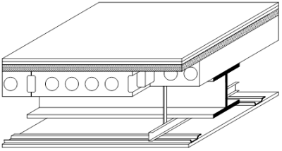
Structural floor
Precast hollow core concrete units supported on steel beams. The precast units should be at least 150 mm thick and weigh at least 300 kg/m2. The joints between adjacent precast units and voids around columns should be filled with grout.
One layer of gypsum-based board with a minimum density of 8 kg/m2. This should be at least 12.5 mm thick standard wall board or a 10 mm gypsum fibre board. The ceiling board may be supported on a proprietary metal frame, timber battens and/or resilient bars. The ceiling board or the support system should not be in direct contact with the steel beam. The distance between the top of the ceiling board and the top of the precast unit should generally be at least 300 mm.
Floor treatment
Typical floor treatments applied to the precast units include isolated screeds and battened floors or platform floors applied over non-isolated screeds.
Construction depth
The overall construction depth is typically 400 to 950 mm.
Expected performance
Airborne: DnT,w + Ctr = 47 to 58 dB
Impact: L’ntw = 39 to 60 dB
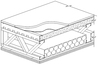
[top]Light steel joists with boards
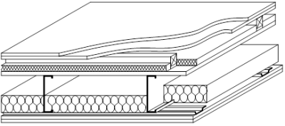
Structural floor
Light steel joists at 400 to 600 mm centres. The light steel joists are generally 150 to 250 mm deep ‘C’ sections. A decking board is fixed to the top of the joists; the decking board may be chipboard, OSB or plywood. The thickness of a chipboard or OSB decking board is typically 18 to 22 mm; a plywood decking board is typically 9 to 15 mm. A resilient isolation tape can be applied to the top of the light steel joists to improve impact sound insulation. This floor is a Robust Detail (E-FS-2) when specified to comply with the requirements given in the Robust Details Handbook[1]
Two layers of gypsum-based board with a minimum density of 22 kg/m2. This is typically two layers of 15 mm sound resistant plasterboard or two layers of 10 mm gypsum fibre board. The ceiling board is supported on resilient bars fixed to the underside of the light steel joists .
Quilt
Mineral wool quilt placed between the joists should be at least 100 mm thick and 10 to 45 kg/m3.
Floor treatment
Battened floor treatments (as shown), platform floor treatments or proprietary screeds are used. Battened floor treatments used with this type of floor should include a layer of 19 mm gypsum-based board under the floor boarding and mineral wool quilt between battens. A platform floor treatment should also include a layer of 19 mm gypsum-based board under the floor boarding.
Construction depth
The overall construction depth is typically 250 to 380 mm.
Expected performance
Airborne: DnT,w + Ctr = 47 to 57 dB
Impact: L’ntw = 44 to 58 dB
[top]Light steel lattice truss with screed
Structural floor
Light steel lattice trusses spaced at 400 to 600 mm centres. The trusses are constructed with light steel ‘C’ sections and are typically 200 to 400 mm deep. Over the trusses is shallow metal decking (16 to 25 mm deep) and a gypsum-based or concrete screed (50 to 70 mm thick). A 6 mm thick resilient isolation tape is applied to the top of the steel joists to improve impact sound insulation.
Two layers of gypsum-based board with a minimum density of 22 kg/m2. Typically two layers of 15 mm sound resistant plasterboard or two layers of 10 mm gypsum fibre board. The ceiling board is supported on resilient bars fixed to the underside of the light steel lattice trusses.
Quilt
Mineral wool quilt placed between the trusses should be at least 100 mm thick and 10 to 45 kg/m3.
Floor treatment
A resilient floor covering consisting of flooring grade chipboard, or a gypsum fibre board, pre-bonded to an acoustic layer. The floor treatment thickness is typically 25 to 48 mm.
Construction depth
The overall construction depth is typically 320 to 500 mm.
Expected performance
Airborne: DnT,w + Ctr = 46 to 56 dB
Impact: L’ntw = 50 to 62 dB
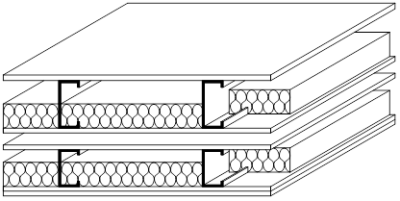
[top]Light steel joists and ceiling for modular construction
Structural floor
Two sets of light steel joists spaced at 400 to 600 mm centres. The upper set of joists support the floor of the upper module and the lower set of joists supports the ceiling of the lower module. The light steel joists are generally 70 to 180 mm deep ‘C’ sections. A chipboard, OSB or plywood layer is fixed to the top of the joists. The thickness of a chipboard or OSB layer is typically 18 to 22 mm, a plywood layer is typically 9 to 18 mm. An isolating strip, typically 3 mm thick, can be applied along the upper set of joists between the joists and the board to improve impact sound insulation.
Two layers of gypsum-based board with a minimum density of 18 kg/m2. Typically, two layers of 12.5 mm sound resistant plasterboard or two layers of 10 mm gypsum fibre board. The ceiling board is fixed to the underside of the lower set of joists.
Quilt
There may be one or two layers (as shown) of quilt placed between the joists. The total depth of mineral wool quilt should be at least 100 mm and 10 to 45 kg/m3.
Floor treatment
Generally, no additional floor treatment is required.
Construction depth
The overall construction depth is typically 300 to 460 mm.
Expected performance
Airborne: DnT,w + Ctr = 46 to 55 dB
Impact: L’ntw = 50 to 60 dB
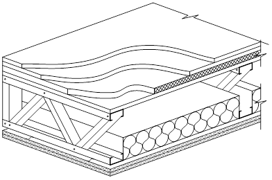
[top]Light steel lattice truss with acoustic boards
Structural floor
Light steel lattice trusses spaced at 400 to 600 mm centres. The trusses are constructed with light steel ‘C’ sections and are typically 250 to 400 mm deep. A decking board is fixed to the top of the trusses; the decking board may be chipboard, OSB or plywood. The thickness of a chipboard or OSB decking board is typically 18 to 22 mm; a plywood decking board is typically 9 to 18 mm. An isolating strip, typically 3 mm thick, can be applied between the trusses and the board to improve impact sound insulation.
Two layers of gypsum-based board with a minimum density of 22 kg/m2. Typically two layers of 15 mm sound resistant plasterboard or two layers of gypsum fibre board. The ceiling board is supported on resilient bars fixed to the underside of the light steel lattice trusses.
Quilt
Mineral wool quilt placed between the trusses should be 100 to 200 mm thick and 10 to 45 kg/m3.
Floor treatment
A platform floor treatment consisting of 18 mm floor grade chipboard over 19 mm gypsum-based board on 25 to 30 mm layer of dense mineral wool quilt (approximately 100 kg/m3).
Construction depth
The overall construction depth is typically 320 to 520 mm.
Expected performance
Airborne: DnT,w + Ctr = 46 to 54 dB
Impact: L’ntw = 35 to 55 dB
[top]Internal floors
This section describes floor constructions suitable for internal floors using light steel joists.
All acoustic performance values quoted are indicative. Manufacturers’ literature, system suppliers and/or an acoustic consultant should be consulted for detailed specifications and expected acoustic performance.
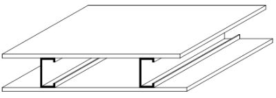
[top]Light steel joist (with quilt)
Structural floor
Light steel joist ‘C’ sections spaced at 400 to 600 mm centres. The light steel joists are generally 80 to 250 mm deep. A chipboard, OSB or plywood layer is fixed to the top of the joists.
Ceiling
One layer of gypsum-based board with a minimum density of 10 kg/m2. Typically one layer of 12.5 mm sound resistant plasterboard or one layer of 10 mm gypsum fibre board.
Quilt
Mineral wool quilt placed between the joists should be 80 to 100 mm thick and 10 to 45 kg/m3.
Floor treatment
No additional floor treatment is required.
Construction depth
The overall construction depth is typically 100 to 270 mm.
Expected performance
Rw = 40 to 43 dB
[top]Light steel joist (without quilt)
Structural floor
Light steel joist ‘C’ sections at least 200 mm deep. A layer of 18 mm tongue and groove flooring grade chipboard at least 18 mm thick.
Ceiling
One layer of gypsum-based board with a minimum density of 15 kg/m2. Typically one layer of 12.5 mm fibre reinforced gypsum-based board or one layer of 10 mm gypsum fibre board.
Quilt
None.
Floor treatment
No additional floor treatment is required.
Construction depth
The overall construction depth is typically 220 to 270 mm.
Expected performance
Rw = 40 dB
[top]Floor treatments
Floor treatments are applied on top of the structural floor to enhance the acoustic performance of the overall floor system, i.e. structural floor, floor treatment and ceiling. The following table shows which floor treatments are suitable for use with different separating floor types.
| Structural floor | Floor treatment | ||||||
|---|---|---|---|---|---|---|---|
| Deep batten floor | Cradle and batten floor | Standard batten floor | Platform floor3 | Shallow platform floor | Sand and cement screed floor | Light-weight screed floor | |
| Composite floor on steel beams | ✔ | ✔ | ✔ | ✔ | ✔ | ✔ | ✔ |
| Precast units on steel beams | ✔ | ✔ | ✔ | ✔ | ✔ | ✔ | ✔ |
| Light steel joists with boards | ✔1 | ✔1 | ✔1 | ✔2 | X | X | ✔ |
| Light steel lattice truss with screed | X | X | X | ✔ | ✔ | X | X |
| Light steel joist and ceiling for modular construction | Generally, no additional floor treatment is required. | ||||||
| Light steel lattice truss with acoustic boards | X | X | X | ✔ | X | X | X |
Key:
✔ - Floor treatment is suitable for use with this floor.
X - Floor treatment is not suitable or not necessary for use with this floor.
1 - Mineral wool quilt should be placed between battens and a 19 mm gypsum-based board should be included under the flooring board.
2 - A 19 mm gypsum-based board should be included under the flooring board.
3 - Applies to platform floor with timber board or gypsum fibre board.
For all floor treatments, separate flanking strips should be used to isolate separating walls from the floor treatment system.
There are many manufacturers of acoustic floor treatments. All acoustic floor treatments must be carefully installed in accordance with the manufacturer’s instructions.
Floors should not be tiled without installing an appropriate resilient material under them otherwise the impact sound transmission will be unacceptable.
The relative performance of floor treatments depends on the type of structural floor to which they are applied and the exact specification of the floor treatment. Factors affecting the performance of the floor treatment are the degree of isolation from the structural floor, the mass of the floor treatment and its depth.
[top]Deep batten floor
The floor treatment consists of:
- Tongue and groove flooring board at least 18 mm thick
- Resilient composite battens at least 70 mm deep (total clearance ≥ 70 mm when loaded to 25 kg/m2). The timber batten is bonded to resilient foam strips that may be at the top or at the bottom.
For additional performance:
- A 19 mm gypsum-based board may be included under the flooring board (optional).
- Mineral wool quilt may be included between the battens (optional).
Services installed in the floor should not bridge the resilient foam strip.
[top]Cradle and batten floor
The floor treatment consists of:
- Tongue and groove flooring board at least 18 mm thick
- Resilient cradle and batten system at least 60 mm deep (Total clearance ≥ 60 mm when loaded to 25 kg/m2). Timber battens are supported on cradles and resilient pads.
For additional performance:
- A 19 mm gypsum-based board may be included under the flooring board (optional).
- Mineral wool quilt may be included between the battens (optional).
Services installed in the floor should not bridge the resilient pads.
[top]Standard batten floor
The floor treatment consists of:
- Tongue and groove flooring board at least 18 mm thick
- Resilient composite standard battens at least 45 mm deep (Total clearance ≥ 45 mm when loaded to 25 kg/m2). The timber batten is bonded to resilient foam strips which may be at the top or at the bottom.
For additional performance:
- A 19 mm gypsum-based board may be included under the flooring board (optional).
- Mineral wool quilt may be included between the battens (optional).
Services installed in the floor should not bridge the resilient foam strip.
[top]Platform floor (Timber board)
The floor treatment consists of:
- Tongue and groove timber flooring board at least 18 mm thick
- Mineral wool resilient layer at least 25 mm thick and approximately 150 kg/m3
- Overall mass per unit area of floor system should be at least 16 kg/m2
- For additional performance, a 19 mm gypsum-based board may be included under the flooring board (optional).
No services should be installed in the floor system.
[top]Platform floor (Gypsum fibre board)
The floor treatment consists of:
- Two layers of gypsum fibre board, each layer at least 10 mm thick.
- Mineral wool resilient layer at least 10 mm and approximately 100 kg/m3 or compressed wood fibre at least 10 mm and approximately 150 kg/m3
- Overall mass per unit area of floor system should be at least 16 kg/m2.
No services should be installed in the floor system.
[top]Shallow platform floor
The floor treatment consists of:
- Tongue and groove flooring board at least 9 mm thick
- A resilient layer (e.g. foam or rubber) pre-bonded to the flooring board.
No services should be installed in the floor system.
[top]Sand and cement screed floor
The floor treatment consists of:
- Sand cement screed, typically 60 to 80 mm thick
- An isolating layer comprised of dense mineral wool and waterproof membrane carefully installed to ensure continuity. Alternatively, a proprietary resilient layer may be used (it must be installed in accordance with the manufacturer’s instructions).
No services should be installed in the floor system.
Care must be taken to avoid air gaps at the edges of the screed.
[top]Light weight screed floor
The floor treatment consist of:
- Gypsum based light weight screed, typically 40 to 70 mm thick
- An isolating layer comprised of dense mineral wool and waterproof membrane carefully installed to ensure continuity. Alternatively, a proprietary resilient layer may be used (it must be installed in accordance with the manufacturer’s instructions).
No services should be installed in the floor system.
Care must be taken to avoid air gaps at the edges of the screed.
[top]Ceiling treatments
Typically, separating floors should have a ceiling treatment of at least one layer of gypsum-based board.
Composite separating floors and precast unit separating floors use a suspended ceiling that is not connected directly to the structural floor but is supported from it. The ceiling treatment options for composite and precast separating floors are shown in the following section and figures. For light steel separating floors the ceiling board is generally supported directly by the structural floor.
For composite separating floors and precast unit separating floors where only one layer of ceiling board and no insulation in the ceiling void is specified, the sound insulation performance of a ceiling treatment can be increased by placing a mineral wool quilt in the ceiling void or by using two layers of gypsum-based board. Including mineral wool quilt in the ceiling void can improve performance by 3 - 4 dB for airborne and 4 - 5 dB for impact sound. Using two layers of gypsum-based board can improve performance by 2 - 4 dB for airborne and 3 - 5 dB for impact sound.
Ceiling treatments must be installed in accordance with the manufacturers’ instructions and all ceiling board joints must be sealed with tape or caulked with sealant.
[top]Metal frame system
Proprietary metal frame systems can be used to hang the ceiling below downstand beams to form a flat soffit.
For in-situ concrete slabs supported by profiled steel decking, i.e. composite floors:
- Ceiling board must be at least 8 kg/m2 of gypsum-based board
- C must be ≥ 300 mm for use with RD (E-FS-1).
For precast unit floors:
- Ceiling board must be at least 8 kg/m2 of gypsum-based board
- D must be ≥ 100 mm with 200 mm deep precast units
- D must be ≥ 150 mm with 150 mm deep precast units.
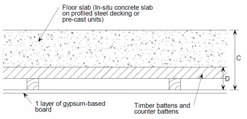
[top]Timber battens
Timber battens fixed to the underside of the slab support the ceiling board close to the slab.
For in-situ concrete slabs supported by profiled steel decking, i.e. composite floors:
- Ceiling board must be at least 8 kg/m2 of gypsum-based board
- C must be ≥ 300 mm for use with RD (E-FS-1).
For precast unit floors:
- Ceiling board must be at least 8 kg/m2 of gypsum-based board
- Only suitable for use with 200 mm deep precast units or 150 mm deep precast units with a structural topping
- D must be ≥ 100 mm.
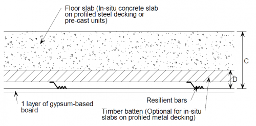
[top]Resilient bar
Proprietary resilient bars decouple the ceiling from the floor slab and enhance acoustic insulation of the floor.
For in-situ concrete slabs supported by profiled steel decking, i.e. composite floors:
- Ceiling board must be at least 8 kg/m2 of gypsum-based board
- C must be ≥ 300 mm for use with RD (E-FS-1)
- Resilient bars may be fixed directly to the underside of the deck.
For precast unit floors:
- Ceiling board must be at least 10 kg/m2 of gypsum-based board
- Only suitable for use with 200 mm deep precast units
- D must be ≥ 65 mm.
[top]References
[top]Further reading
- Carl Hopkins. Sound insulation. Elsevier, Butterworth-Heinemann, 2007.
- M.W. Simons & J. R. Waters. Sound Control in Buildings. A guide to Part E of the Building Regulations. Blackwell publishing, 2004.
- Technical paper No. 8. Acoustic Guide for Metal Roof and Wall Cladding Systems, MCRMA
- BS EN ISO 10140: 2021 Acoustics. Laboratory measurement of sound insulation of building elements. Various parts. British Standards Institution.
[top]Resources
- SCI P351 Precast concrete floors in steel framed buildings
- SCI P372 Acoustic Detailing for Steel Construction
- SCI P320 Acoustic performance of light steel framed systems
- SCI P322 Acoustic performance of composite floors
- SCI P336 Acoustic detailing for multi-storey residential buildings
- SCI P371 Acoustic performance – Case Studies
- SCI Advisory Desk AD 313. Precast concrete floors in steel framed buildings: Achieving floor diaphragm action and acoustic performance
- SCI Acoustic performance prediction tool for separating floors and walls
[top]See also
- Introduction to acoustics
- Acoustic regulations
- Acoustic performance of walls
- Junction details for acoustic performance
- Integration of elements for acoustic performance
- Steel construction products
- Floor systems


