Difference between revisions of "Introduction to acoustics"
| (3 intermediate revisions by the same user not shown) | |||
| Line 16: | Line 16: | ||
*[[Introduction_to_acoustics#Impact_sound_insulation|Impact sound]] | *[[Introduction_to_acoustics#Impact_sound_insulation|Impact sound]] | ||
<br> | <br> | ||
| − | Sound insulation can be described in a variety of ways depending on the type of sound and the method of measurement. This can initially be confusing when trying to evaluate performance quoted in manufacturers’ literature against client specifications and [[Acoustics_regulations#Part_E_of_the_building_regulations|Building Regulation requirements]]. The following sections explain some of the main terms. More comprehensive descriptions are given in BS EN ISO 10140<ref name="No1">BS EN ISO 10140: | + | Sound insulation can be described in a variety of ways depending on the type of sound and the method of measurement. This can initially be confusing when trying to evaluate performance quoted in manufacturers’ literature against client specifications and [[Acoustics_regulations#Part_E_of_the_building_regulations|Building Regulation requirements]]. The following sections explain some of the main terms. More comprehensive descriptions are given in BS EN ISO 10140<ref name="No1">BS EN ISO 10140:2021 Acoustics. Laboratory measurement of sound insulation of building elements. Various parts. BSI</ref> |
===Airborne sound insulation=== | ===Airborne sound insulation=== | ||
| Line 30: | Line 30: | ||
===Single figure rating values=== | ===Single figure rating values=== | ||
{{#image_template:image=File:F1_3a.png|caption=Calculation of single figure value D<sub>nT,w</sub>|align=right|wrap=true|width=400}} | {{#image_template:image=File:F1_3a.png|caption=Calculation of single figure value D<sub>nT,w</sub>|align=right|wrap=true|width=400}} | ||
| − | Sound insulation is measured at a number of different frequencies, usually at 16 one-third octave bands from 100 Hz to 3150 Hz. However, for many purposes, including the requirements for dwellings given in [[Acoustics_regulations#Part_E_of_the_building_regulations|Building Regulations]], a single figure rating is required. There are several methods that could be used to reduce the sound insulation values at the sixteen individual frequencies to a single figure value. An obvious method is to take the arithmetic mean, but very high levels of sound insulation at some frequencies can offset poor performance at others. The most common method of overcoming this is to compare the measured results with a set of sixteen reference results, i.e. a reference curve. The reference curve is defined in BS EN ISO 717-1<ref name="No2">BS EN ISO 717-1: | + | Sound insulation is measured at a number of different frequencies, usually at 16 one-third octave bands from 100 Hz to 3150 Hz. However, for many purposes, including the requirements for dwellings given in [[Acoustics_regulations#Part_E_of_the_building_regulations|Building Regulations]], a single figure rating is required. There are several methods that could be used to reduce the sound insulation values at the sixteen individual frequencies to a single figure value. An obvious method is to take the arithmetic mean, but very high levels of sound insulation at some frequencies can offset poor performance at others. The most common method of overcoming this is to compare the measured results with a set of sixteen reference results, i.e. a reference curve. The reference curve is defined in BS EN ISO 717-1<ref name="No2">BS EN ISO 717-1:2013. Acoustics. Rating of sound insulation in buildings and of building elements. BSI</ref> and is based on the relative human perception of different frequencies of sound. The rating is made by considering only those sound insulation values which fall short of the reference curve. In this way, one or two very good results have much less effect on the single figure value. The method used for calculating a single figure airborne sound insulation value is shown graphically in the following figure. The position of the reference curve is moved up or down until the sum of the adverse deviations is less than or equal to 32 dB but as close as possible to 32 dB. The D<sub>nT,w</sub> value is then read from the position at 500 Hz point of the reference curve. A similar method is used for impact sound. |
The single figure values are called: | The single figure values are called: | ||
| Line 79: | Line 79: | ||
*Carl Hopkins. Sound insulation. Elsevier, Butterworth-Heinemann, 2007. | *Carl Hopkins. Sound insulation. Elsevier, Butterworth-Heinemann, 2007. | ||
*M.W. Simons & J. R. Waters. Sound Control in Buildings. A guide to Part E of the Building Regulations. Blackwell publishing, 2004. | *M.W. Simons & J. R. Waters. Sound Control in Buildings. A guide to Part E of the Building Regulations. Blackwell publishing, 2004. | ||
| − | *[ | + | *[https://www.tatasteeleurope.com/sites/default/files/Colorcoat_Acoustic_TechPaper_FINAL.pdf Acoustic performance of pre-finished steel cladding systems] |
==Resources== | ==Resources== | ||
Latest revision as of 07:59, 19 April 2022
The way in which sound is allowed to travel into, out of or around a building is an important consideration for most types of buildings. The construction details of the floors, walls and their junctions in a building are the key to its acoustic insulation. It is first important to understand what sound is and how it behaves. This article provides an overview of the types of sound and the principles of acoustic design and detailing.
[top]Sound
Sound is produced when objects vibrate in air. The movement causes air particles to vibrate giving rise to rapid pressure fluctuations that are detected by the ear. The manner in which humans perceive sound governs the way it is measured and described. Two important characteristics of sound which humans can detect are:
- The level or loudness
- The pitch or frequency.
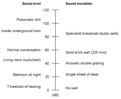
Sound levels and sound insulation, i.e. attenuation, values are expressed in decibels (dB), whilst pitch or frequency is expressed in Hertz (Hz). In the case of sound levels, the decibel rating is a representation of the volume of the sound whilst in the case of sound insulation values, it is a measure of the amount by which sound transmitted from one room to another is reduced by the separating construction. Some typical sound levels and sound insulation values are shown in the figure above right.
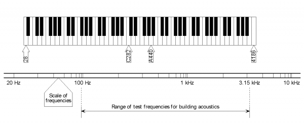
The sound insulation properties of walls or floors vary with frequency and, as most sounds are a mixture of several different frequencies, certain frequencies within a sound are likely to be attenuated more effectively than others by a given construction. Low pitched sounds, i.e. low frequencies, are normally attenuated less than high pitched sounds, i.e. high frequencies. Therefore, the sound reduction characteristics of walls and floors are measured at a number of different frequencies across the human hearing range. The normal frequency range of measurements is shown in the figure below.
There are two types of sound that should be considered in the acoustic design of buildings:
Sound insulation can be described in a variety of ways depending on the type of sound and the method of measurement. This can initially be confusing when trying to evaluate performance quoted in manufacturers’ literature against client specifications and Building Regulation requirements. The following sections explain some of the main terms. More comprehensive descriptions are given in BS EN ISO 10140[1]
[top]Airborne sound insulation
Airborne sound insulation is important for both walls and floors. Airborne sound insulation between rooms can be measured by generating a steady sound of a particular frequency in one room (the source room) and comparing it with sound in a second adjacent room (the receiving room). These measurements are made at a number of different frequencies. The difference between the two levels is referred to as the level difference D. This level difference is influenced by the amount of acoustic absorption in the receiving room. When a sound wave reaches a surface it will be partly reflected off the surface back into the room and continue travelling in a new direction, and it will be partly absorbed by the surface. The sound absorption of a room can be estimated by measuring the reverberation time T. The reverberation time is the time taken for the reverberant noise to decay by 60 dB. A sound created in a room with a long reverberation time will sound louder than the same sound created in a room with a short reverberation time. In order that airborne sound insulation measurements in different buildings may be compared, the level differences can be adjusted to a standard reverberation time of 0.5 seconds. This gives the standardised level difference DnT.
Individual building elements such as partitions, doors or windows can be tested in acoustic laboratories. These laboratories comprise two massively constructed adjacent rooms that are isolated against flanking transmission and connected by an aperture containing a test panel of the building element. The level difference is measured between the two rooms and the result adjusted to be independent of both the area of the panel tested and the acoustic absorption of the room. The resulting value is the sound reduction index R.
[top]Impact sound insulation
Impact insulation is generally only relevant to floors. A standard impact sound source (a tapping machine consisting of automated hammers) is used to strike the floor repeatedly at a standard rate. The resulting sound in the receiving (downstairs) room is measured and this value is termed the impact sound pressure level L. Measurements in buildings can be standardised to a reverberation time of 0.5 seconds. This gives the standardised impact sound pressure level L’nT which is a field measurement. Tests in laboratories, normalised for area and absorption give the normalised impact sound pressure level Ln.
This test method means that the better the impact sound insulation, the lower the value of L’nT or Ln.
[top]Single figure rating values
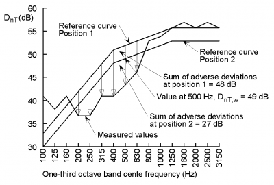
Sound insulation is measured at a number of different frequencies, usually at 16 one-third octave bands from 100 Hz to 3150 Hz. However, for many purposes, including the requirements for dwellings given in Building Regulations, a single figure rating is required. There are several methods that could be used to reduce the sound insulation values at the sixteen individual frequencies to a single figure value. An obvious method is to take the arithmetic mean, but very high levels of sound insulation at some frequencies can offset poor performance at others. The most common method of overcoming this is to compare the measured results with a set of sixteen reference results, i.e. a reference curve. The reference curve is defined in BS EN ISO 717-1[2] and is based on the relative human perception of different frequencies of sound. The rating is made by considering only those sound insulation values which fall short of the reference curve. In this way, one or two very good results have much less effect on the single figure value. The method used for calculating a single figure airborne sound insulation value is shown graphically in the following figure. The position of the reference curve is moved up or down until the sum of the adverse deviations is less than or equal to 32 dB but as close as possible to 32 dB. The DnT,w value is then read from the position at 500 Hz point of the reference curve. A similar method is used for impact sound.
The single figure values are called:
- Standardised weighted level difference DnT,w when generated from DnT
- Weighted sound reduction Rw when generated from R
- Standardised weighted impact sound pressure level L’nT,w when generated from L’nT
- Normalised weighted impact sound pressure level Ln,w when generated from Ln.
[top]Acoustic detailing
[top]Direct and flanking transmission
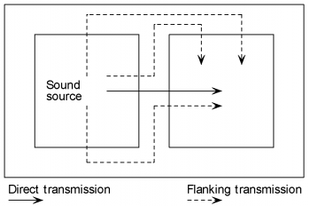
Where a room is separated from another room, sound can travel by two routes: directly through the separating structure called direct transmission, and around the separating structure through adjacent building elements called flanking transmission. These routes are indicated in the following figure.
Sound insulation for both routes is controlled by the following three characteristics:
Direct transmission depends upon the properties of the separating wall or floor and can be estimated from laboratory measurements. Flanking transmission is more difficult to predict because it is influenced by the details of the junctions between the building elements and the quality of construction on site. It is notable that, in certain circumstances, such as where separating walls have a high standard of acoustic insulation but side walls are constructed to lower standards and are continuous between rooms, flanking transmission can account for the passage of more sound than direct transmission. It is therefore important that the junctions between separating elements are detailed and built correctly to minimise flanking sound transmission.
[top]Mass
Transmission of airborne sound across a solid wall or a single skin partition will obey what is known as the mass law. This law may be expressed in a variety of ways. In principle, the law suggests that the sound insulation of a solid element will increase by approximately 5 dB per doubling of mass. The mass law is applicable between 10 and 1000 kg/m2.
[top]Isolation
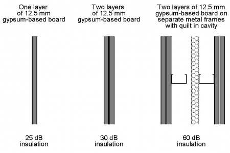
Lightweight framed construction achieves far better standards of airborne sound insulation than the mass law would suggest because of the presence of a cavity and therefore a degree of isolation between the various layers of the construction. It has been demonstrated that the sound insulation of individual elements within a double skin partition tend to combine together in a simple cumulative linear relationship. The overall performance of a double skin partition can therefore generally be determined by simply adding together the sound insulation ratings of its constituent elements. In this way, two comparatively lightweight partitions of 25 to 30 dB sound reduction can be combined to give an acoustically enhanced partition with a 50 to 60 dB sound reduction, whereas the mass law alone would suggest only a 5 dB improvement. This is the basis of many lightweight partition systems, and is further illustrated in the figure right.
The width of the cavity between separate layers is important to the acoustic performance of a wall. The cavity width should be at least 40 mm.
[top]Sealing
It is important to provide adequate sealing around floors and partitions because even a small gap can lead to a marked deterioration in acoustic performance. Joints between walls and between walls and ceilings should be sealed with tape or caulked with sealant. Where walls abut profiled metal decks, or similar elements, mineral wool packing and acoustic sealants may be required. Where there are movement joints at the edges of walls, special details are likely to be necessary; advice should be sought from manufacturers.
Ideally, wall linings, e.g. gypsum-based board, should not be penetrated by services. This is particularly important for separating walls between dwellings. Where service penetrations do occur in sensitive locations, particular attention should be given to the way in which these are detailed.
[top]Construction quality
The acoustic performance of a building can be sensitive to the quality of the workmanship. Gaps, absent absorption quilt or loss of isolation between elements can all seriously impair the sound insulation performance or increase the amount of flanking sound transmission of a separating wall or floor.
Material substitution or changes to construction details can reduce the sound insulation performance of separating elements. Apparently similar products can have significantly different acoustic properties. Therefore, any changes to construction details or material substitutions should be approved by a suitably qualified person such as an acoustic consultant.
One of the recognised benefits of steel construction and off-site construction in particular, is that the quality and consistency of construction is improved. Therefore, the acoustic performance is more reliable. Off-site prefabrication improves quality by factory-controlled production, and is less dependent on site trades and the weather. Steel does not shrink, warp, or creep under load, and therefore does not contribute to cracking or deterioration of the non-structural elements and finishes; gaps and sound paths are not created and the acoustic performance is maintained.
To ensure that the quality of construction is of the required standard, trained installers should be used and there should be sufficient site supervision.
[top]References
[top]Further reading
- Carl Hopkins. Sound insulation. Elsevier, Butterworth-Heinemann, 2007.
- M.W. Simons & J. R. Waters. Sound Control in Buildings. A guide to Part E of the Building Regulations. Blackwell publishing, 2004.
- Acoustic performance of pre-finished steel cladding systems
[top]Resources
- SCI P372 Acoustic Detailing for Steel Construction
- SCI P371 Acoustic performance – Case Studies
- SCI Acoustic performance prediction tool for separating floors and walls
[top]See also
- Acoustic regulations
- Acoustic performance of walls
- Acoustic performance of floors
- Junction details for acoustic performance
- Integration of elements for acoustic performance


