


Difference between revisions of "Visually expressed structural forms"
| Line 51: | Line 51: | ||
Where columns are exposed, consideration of the shape of the member and the appropriate [[Fire_protecting_structural_steelwork|fire protection]] system are important to the choice of the structural solution. Tubular or [[Steel_construction_products#Structural hollow sections|hollow section]] columns are often used in these cases. Improved [[Structural_fire_resistance_requirements|fire resistance]] can be achieved by the use of [[Fire_protecting_structural_steelwork#Intumescent Coatings|intumescent coatings]] or by [[Hollow_sections_in_fire#Concrete filled and reinforced structural hollow sections|concrete filling]]. | Where columns are exposed, consideration of the shape of the member and the appropriate [[Fire_protecting_structural_steelwork|fire protection]] system are important to the choice of the structural solution. Tubular or [[Steel_construction_products#Structural hollow sections|hollow section]] columns are often used in these cases. Improved [[Structural_fire_resistance_requirements|fire resistance]] can be achieved by the use of [[Fire_protecting_structural_steelwork#Intumescent Coatings|intumescent coatings]] or by [[Hollow_sections_in_fire#Concrete filled and reinforced structural hollow sections|concrete filling]]. | ||
| − | Tubular columns are structurally efficient and can | + | Tubular columns are structurally efficient and can be designed to be very slender. They are used in applications where the minimum amount of intrusion into the space is sought, or where the external appearance of the column is to be preserved. Connections to tubular columns are often expressed as part of the overall [[Concept_design|structural concept]]. Columns are [[Construction#Steel erection|erected]] in two or three storey high lengths and splices are usually made by end plates or side plate connections just above floor height, in order to avoid intrusion into the floor space. |
Circular columns are particularly attractive in public spaces, such as [[Retail_buildings#Shopping centres|shopping malls]], railway stations, airports and [[Leisure_buildings#Theatres and auditoria|auditoria]], due to their slenderness and lightness. The torsional properties of ‘box’ or circular sections may also be used to provide torsional resistance to roofs that are curved in the horizontal plane. The example left shows the use of slender tubular columns to support a 6 storey high [[Steel-supported_glazed_facades_and_roofs#Atrium Roofs and Sky lights|glazed wall and atrium roof]]. | Circular columns are particularly attractive in public spaces, such as [[Retail_buildings#Shopping centres|shopping malls]], railway stations, airports and [[Leisure_buildings#Theatres and auditoria|auditoria]], due to their slenderness and lightness. The torsional properties of ‘box’ or circular sections may also be used to provide torsional resistance to roofs that are curved in the horizontal plane. The example left shows the use of slender tubular columns to support a 6 storey high [[Steel-supported_glazed_facades_and_roofs#Atrium Roofs and Sky lights|glazed wall and atrium roof]]. | ||
Latest revision as of 13:50, 11 March 2022
The visual expression of a structure requires an understanding of structural function, for example:
- Braced frames with nominally pinned connections and vertical bracing are the simplest structural solution and there are various ways in which the connections and bracing may be used to visual effect.
- Rigid or continuous frames are often used in low-rise buildings or in large-span structures, and their connections are an important part of the design solution.
- Arches and curved structures offer opportunities for architectural expression due to their elegant shape.
- Tension structures use cables or rods together with posts or masts to form a ‘tent-type’ enclosure. The cables or rods are often external to the envelope, and offer considerable opportunity for architectural expression.
Arch and tension structures rely on the compressive and tensile properties of steel. Arches often use tubular or ‘box’ sections because of their efficient action in compression. Tension structures comprise cables or rods acting in tension together with tubular masts acting in compression.

[top]Exposed steelwork in multi-storey buildings
Main articles: Braced frames, Continuous frames, Simple connections There are relatively few opportunities for architectural expression in the steel structure of multi-storey buildings because generally, most of the structure is concealed. However, there are opportunities to use exposed steelwork in the entrance and atrium areas and by using concrete-filled columns. In recent years, architects have explored the possibility of using structural systems in unexpected ways; this is illustrated by the following examples:
- Alsop’s Paletsra building in London used inclined, concrete filled tubular columns at the ground floor level and three projecting floors at the 10th floor level. The structure used pairs of cellular beams placed either side of the columns.
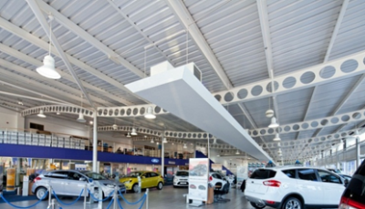
- In Birmingham’s new city hall offices, the cellular beams were designed with alternate elongated and circular openings which were coated with intumescent coating and were exposed as part of the expression of the structure in the internal space.
- Woolwich’s Council office and library used exposed curved precast units designed as part of the fabric energy storage system of the building. The steel beams projected above the top of the precast units and had large rectangular openings so that services and ducts could be distributed on top of the floor. A 500 mm deep access floor was supported by the floor slab and the under-floor services arrangement provided air supply at floor level.
- The More London 7 building has, as part of the design concept, a saw tooth façade made by welding triangulated steel pieces to the edge beams.
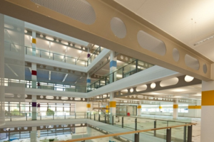
Exposed cellular beams with elongated and circular openings
(Birmingham City Council offices)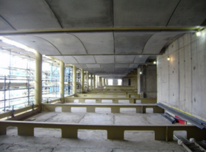
Precast concrete slabs supported by deep steel beams in which services are placed on the floor slab
(Woolwhich Town Hall)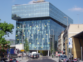
Inclined steel columns at ground floor and projecting upper floors
(Palestra Building, Southwark, London)


[top]Curved beams and roofs
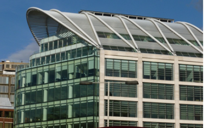
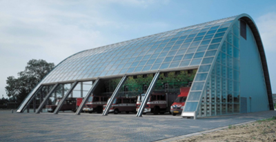
Curved roof structures provide many architectural opportunities for expression, particularly where the walls and roof are combined in one overall structural solution, so that the demarcation between these elements is removed. The physical nature of these roofs or enclosures is that they are curved to a radius to achieve maximum usable space internally.

Castellated and cellular curved beams have been used successfully in long-span roofs with intermediate supports, as shown. Here the lightness of the highly perforated sections is combined with the ability to curve the sections in the re-welding process.

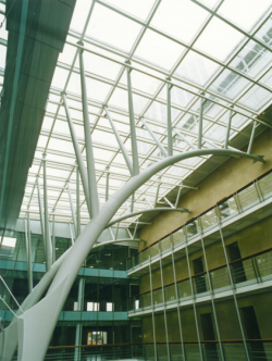

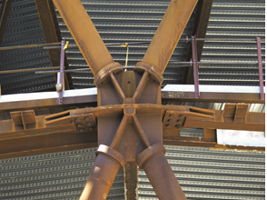
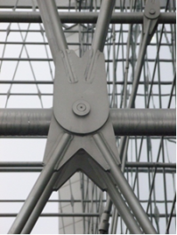
Curved roofs may be formed in one direction by using single-curved tubular members or, in two directions, by using double-curved assemblies. Space frames may also be designed to form curved enclosures. The use of ‘column trees’ to support roofs has been used to great architectural effect in airport terminals and other public spaces. The figure shows the use of curved tubular members with pairs of welded ‘branches’ to support an atrium roof.
Inclined curved members may be connected at their ends and crest and used to create not only usable roof space but also visual appeal in multi-storey office buildings. The horizontal forces at the pinned ends of the curved roof members are resisted by tension in the beams at roof level.

[top]Arch structures

Arches are convex structures that are designed primarily to resist compression, as a result of their shape and the uniform loading acting on them. The most efficient shape for an arch, when subject to uniform loading, is a parabola but they can be circular, or even formed from multiple linear elements. Arches also resist bending moments that are induced due to non-uniform or asymmetric loading, or the deviation of the arch from the idealised shape in which the lines of thrust (compression) are located within the member cross section.
Arches react either against foundations or buttresses, or conversely they can be tied at their base to form a tied arch which does not lead to external horizontal forces. Arches usually have pinned bases, whose details are emphasised, but they may also be encased in their foundations to provide fixity.
Arches in steel may be made of I-sections that are either curved to shape, or made in sections from multiple straight lengths. Arches can also be in the form of fabricated members, such as trusses. An excellent example of external and internal tied arches is the 10-storey Exchange House in Broadgate, London where the four parabolic segmented tied arches span the full 78m across the railway tracks entering Liverpool Street Station.

[top]Exposed columns

Where columns are exposed, consideration of the shape of the member and the appropriate fire protection system are important to the choice of the structural solution. Tubular or hollow section columns are often used in these cases. Improved fire resistance can be achieved by the use of intumescent coatings or by concrete filling.
Tubular columns are structurally efficient and can be designed to be very slender. They are used in applications where the minimum amount of intrusion into the space is sought, or where the external appearance of the column is to be preserved. Connections to tubular columns are often expressed as part of the overall structural concept. Columns are erected in two or three storey high lengths and splices are usually made by end plates or side plate connections just above floor height, in order to avoid intrusion into the floor space.
Circular columns are particularly attractive in public spaces, such as shopping malls, railway stations, airports and auditoria, due to their slenderness and lightness. The torsional properties of ‘box’ or circular sections may also be used to provide torsional resistance to roofs that are curved in the horizontal plane. The example left shows the use of slender tubular columns to support a 6 storey high glazed wall and atrium roof.
Another example of the use of circular columns is in this underground car park, where the deep sheet piling was exposed, and the circular steel columns were manufactured with a fabricated ‘shear head’ that transferred the high shear forces from the flat concrete slab to the columns.
Tubular sections may also be used as heavily loaded columns or inclined struts to support canopy roofs. Tubular sections are often designed for reversal of loading such as in wind uplift conditions which may cause tension members to act in compression.
One excellent early example of the combined use of section types is the Renault Parts Distribution Centre in Swindon, UK, where circular tubular columns supported a framework of tapered beams suspended from the column apex and shaft.
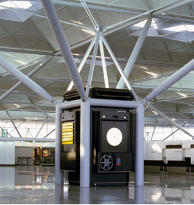
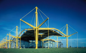
Single or clustered tubular columns may themselves form a basic structure with opportunity for architectural expression. Sometimes the separation between column and truss or beam elements is less clear, as in the case where ‘tree-like’ structures are devised. This kind of expression was used at Stansted airport, in which the group of columns acted as a rigid framework under vertical and lateral loads and also enclosed services units.
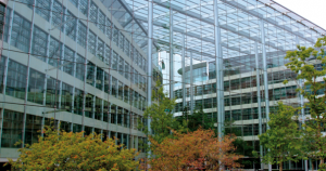
Tubular steel columns in 6 storey entrance atrium at Tower Place, London
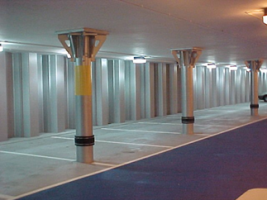
Circular columns in a basement car park supporting a concrete flat slab by use of fabricated shear heads
Renault Parts Distribution Centre, Swindon


[top]Fabricated components

Fabricated steel sections are used where rolled beams are not suitable due to their shape or dimensions. They can be made of a variety of components including:
- Steel plates welded to create I or H beams, or tapered beams.
- I beams cut into Tee sections
- Tubular sections with welded fins.
The Gherkin in London used a diagrid of tubular members to form the ‘shell’ of the load-bearing façade structure. The steel nodes were used to provide the attachment points between the tubular sections and also to bolt to the perimeter beams of the floor.
The curved beams at Stratford Station, London, were welded from plate and stiffened at points of high curvature. Cast steel footings connected the curved beams to the concrete ground beam, accentuating the local curvature (see below)
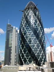
Swiss Re Building, London
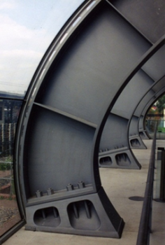
Stratford Station, London


[top]Tension structures
In tension structures, the ‘ties’ are designed to resist only tension and are crucial elements in the structural concept. Tall compression members or ‘masts’ provide the necessary vertical support, and these masts are located fully or partially outside the enclosure. Cable-stayed roofs, suspended structures, cable nets and membrane structures are all types of tension structures.
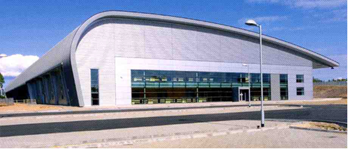
Tension structures can have clear advantages for the roofs of long-span structures or enclosures where the internal function of the space is an important aspect of the design concept. The tension forces are resisted externally by the weight of concrete foundations or by tension piles. In smaller-scale applications, their use is more likely to depend upon a combination of technical and architectural arguments, such as the desire for a lightweight or membrane roof, or to support a glass wall with the minimum of obstruction.

Tension structures use cables, steel ropes or solid, threaded bars. The cables can be impregnated and sheathed with nylon or PVC or can be greased and galvanized for corrosion protection. Cables have high-tensile strength but often low ductility. Fitments to steel ropes provide the coupling mechanism to the adjacent structure. Special consideration to the aerodynamic damping of long ties on cables when exposed to wind is required.
Individual rods are made from solid steel, whose ends are threaded to attach to steel couplers. Rods are linear elements and are stiffer than cables, which will sag naturally. Rods are usually lightly tensioned on erection of the frame.
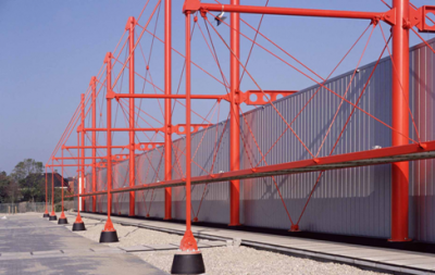
A ‘wind girder’ may be designed as a horizontal truss to transfer wind loads to vertical bracing and, in this application, they can be pre-tensioned so that the reversal of wind loads does not cause compression. Steel flat plates or smaller circular hollow sections (CHS) may be used in some simple tension structures, although they are visually more obtrusive.
The image shows a roof of a large warehouse that is supported by external masts and cables. The vertical connections to the foundations are small CHS in this case.
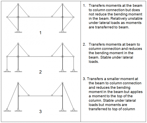
The structural action of various forms of cable stayed roofs is presented below. System 2 approximates to that shown right.


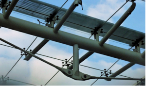
Tension elements can be also used in simpler structural components. The use of a tie rod member as the bottom chord to a tubular roof beam structure to support a glazed roof is shown. This simple but elegant system takes advantage of the torsional stiffness of the tubular section to prevent the central post from rotating under compression.
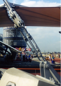
The figure (right) shows the use of different types of tension couplers and tightening systems used to attach to the membrane roof of London’s Millennium Dome (now O2 Arena).

[top]Expression of bracing
Diagonal bracing offers the clearest and most direct visual and graphic representation of its action. When brought to the exterior, bracing is often used to ornament the building as well as to serve a structural function. Bracing used for visual effect can be more than the minimum necessary for structural purposes.
In multi-storey buildings, the structural importance of the bracing members means that their size and detailing must conform to sensible load paths by minimising eccentricities and points of weakness at the connections. Welded stiffeners are often required to transfer forces across highly stressed members.
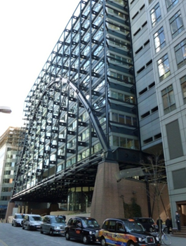
At a macro-level, the bracing can be emphasised on the building elevation, as is often done on high-rise buildings, such as Broadgate tower and Heron tower in London. Another highly visual use of external bracing was expressed externally at Canon Street station in London. This 8 storey building is supported by two X braced assemblies designed in the form of lens shapes connected by tubular ties around the perimeter of the elevation. The corner nodes were thoughtfully designed to be visually attractive as well as being functionally efficient.
- Expressed external bracing
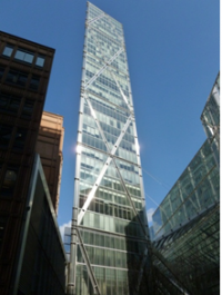
Broadgate Tower, London


At a more detailed scale, X bracing can be used for visual and compositional effect, as shown, where, in the first example, the external steelwork is supported by circular hollow sections connected by couplers and in the second example by welded stainless steel bars.
- Exposed bracing nodes
Sanomat Building, Helsinki


[top]Further reading
- Steel Designers' Manual 7th Edition. Editors B Davison & G W Owens. The Steel Construction Institute 2012
- Architectural Design in Steel – Trebilcock P and Lawson R M published by Spon, 2004
[top]Resources
- SCI P167 Architectural Teaching Resource Studio Guide, 2000
- Best Practice in Steel Construction: Commercial Buildings
- Steel Buildings in Europe - Multi-storey buildings:
- EP37 Best Practice in Steel Construction – Industrial Buildings, Guidance for architects, designers & constructors
- Steel Buildings in Europe - Single storey buildings: