


Trusses
A truss is essentially a triangulated system of straight interconnected structural elements. The most common use of trusses is in buildings, where support to roofs, the floors and internal loading such as services and suspended ceilings, are readily provided. The main reasons for using trusses are:
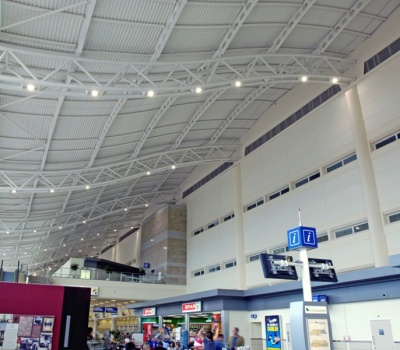

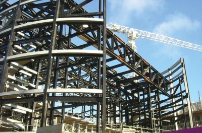
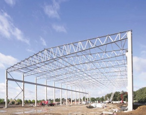
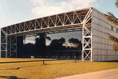
Robin Hood Airport, Doncaster
(Image courtesy of Tubecon)
- Long span
- Lightweight
- Reduced deflection (compared to plain members)
- Opportunity to support considerable loads.
The penalty, however, is increased fabrication costs .
The article describes alternative forms of truss, where and why different forms might be appropriate and introduces design considerations. Primarily, pin jointed trusses are discussed, with some discussion of rigid-jointed Vierendeel trusses.
[top]Definition of a truss
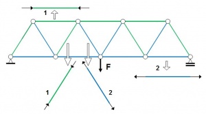

1 - Compression axial force
2 - Tension axial force
A truss is essentially a triangulated system of (usually) straight interconnected structural elements; it is sometimes also referred to as an open web girder. The individual elements are connected at nodes; the connections are often assumed to be nominally pinned. The external forces applied to the system and the reactions at the supports are generally applied at the nodes. When all the members and applied forces are in a same plane, the system is a plane or 2D truss.
The principal force in each element in a truss is axial tension or compression.
Overview of trusses
[top]Use of trusses in buildings
Trusses are used in a broad range of buildings, mainly where there is a requirement for very long spans, such as in airport terminals, aircraft hangers, sports stadia roofs, auditoriums and other leisure buildings. Trusses are also used to carry heavy loads and are sometimes used as transfer structures. This article focuses on typical single storey industrial buildings, where trusses are widely used to serve two main functions:
- To carry the roof load
- To provide horizontal stability.
Two types of general arrangement of the structure of a typical single storey building are shown in the figure below.

|

|
| Lateral stability provided by portal trusses.
No longitudinal wind girder. |
Building braced in both directions.
Longitudinal stability provided by transverse wind girder and vertical bracings (green) |
In the first case (left) the lateral stability of the structure is provided by a series of portal trusses; the connections between the truss and the columns provide resistance to a global bending moment. Loads are applied to the portal structure by purlins and side rails.
In the second case, (right) each truss and the two columns between which it spans, constitute a simple structure; the connection between the truss and a column does not resist the global bending moment, and the two column bases are pinned. Bracing in both directions is necessary at the top level of the simple structure; it is achieved by means of a longitudinal wind girder which carries the transverse forces due to wind on the side walls to the vertical bracing in the gable walls. Longitudinal stability is also provided by a wind girder in the roof and vertical bracing in the elevations.
[top]Types of trusses
Trusses comprise assemblies of tension and compression elements. Under gravity loads, the top and bottom chords of the truss provide the compression and tension resistance to overall bending, and the bracing resists the shear forces. A wide range of truss forms can be created. Each can vary in overall geometry and in the choice of the individual elements. Some of the commonly used types are shown below.
[top]Pratt truss ('N' truss)
Pratt trusses are commonly used in long span buildings ranging from 20 to 100 m in span. In a conventional Pratt truss, diagonal members are in tension for gravity loads. This type of truss is used where gravity loads are predominant (see below left). An alternative Pratt truss is shown (below right) where the diagonal members are in tension for uplift loads. This type of truss is used where uplift loads are predominant, which may be the case in open buildings such as aircraft hangers.

Pratt truss (gravity loads)

Pratt truss (uplift loads)


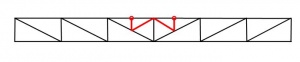
It is possible to add secondary members (as illustrated below left) to:
- Create intermediate support points for applied loads
- Limit the buckling length of members in compression (although in a 2D truss, the buckling length is only modified in one axis).
For the Pratt truss and any of the types of truss mentioned below, it is possible to provide either a single or a double slope to the upper chord of a roof supporting truss. An example of a double (duo-pitch) Pratt truss is shown below.
Pratt truss with secondary members
Duo-pitch Pratt truss


(Image courtesy of Elland Steel Structures Ltd.)
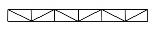
[top]Warren truss

(Image courtesy of Billington Structures Ltd.)
In this type of truss, diagonal members are alternatively in tension and in compression. The Warren truss has equal length compression and tension web members, and fewer members than a Pratt truss. A modified Warren truss may be adopted where additional members are introduced to provide a node at (for example) purlin locations.
Warren trusses are commonly used in long span buildings ranging from 20 to 100 m in span.
This type of truss is also used for the horizontal truss of gantry/crane girders.

[top]North light truss

North light trusses are traditionally used for short spans in industrial workshop-type buildings. They allow maximum benefit to be gained from natural lighting by the use of glazing on the steeper pitch which generally faces north or north-east to reduce solar gain. On the steeper sloping portion of the truss, it is typical to have a truss running perpendicular to the plane of the North Light truss, to provide large column-free spaces.
The use of north lights to increase natural daylighting can reduce the operational carbon emissions of buildings although their impact should be explored using dynamic thermal modelling. Although north lights reduce the requirement for artificial lighting and can reduce the risk of overheating, by increasing the volume of the building they can also increase the demand for space heating. Further guidance is given in the Target Zero Warehouse buildings design guide .
[top]Saw-tooth truss
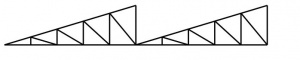

A variation of the North light truss is the saw-tooth truss which is used in multi-bay buildings. Similar to the North light truss, it is typical to include a truss of the vertical face running perpendicular to the plane of the saw-tooth truss.
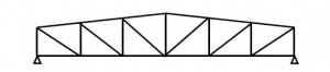
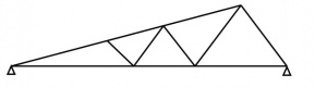
[top]Fink truss
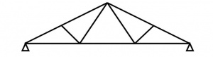

The Fink truss offers economy in terms of steel weight for short-span high-pitched roofs as the members are subdivided into shorter elements. There are many ways of arranging and subdividing the chords and internal members.
This type of truss is commonly used to construct roofs in houses.
[top]Aspects of truss design for roofs
[top]Truss or I beam
For the same steel weight, it is possible to get better performance in terms of resistance and stiffness, with a truss than an I beam. This difference is greater for long spans and/or heavy loads. The full use of this advantage is achievable if the height of the truss is not limited by criteria other than the structural efficiency, e.g. a limit on total height of the building. However, fabrication of a truss is generally more time consuming than for an I beam, even considering that modern fabrication equipment is highly efficient.
The balance between minimum weight and minimum cost depends on many conditions: the equipment of the fabrication factory, the local cost of manufacturing; the steel unit cost, etc. Trusses generally give an economic solution for spans over 20 m.
An advantage of the truss design for roofs is that ducts and pipes that are required for operation of the buildings services can be installed through the truss web, i.e. service integration.
[top]General geometry
For efficient structural performance, the ratio of span to truss depth should be chosen in the range 10 to 15. The architectural design of the building determines its external geometry and governs the slope(s) given to the top chord of the truss. The intended use of the internal space can lead either to the choice of a horizontal bottom chord, e.g. where conveyors must be hung under the chord, or to an inclined bottom chord, to allow maximum space to be provided.
For an efficient layout of the truss members between the chords, the following is advisable:
- The inclination of the diagonal members in relation to the chords should be between 35° and 55°
- Point loads should only be applied at nodes
- The orientation of the diagonal members should be such that the longest members are subject to tension (the shorter ones being subject to compression).
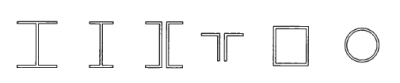
[top]Types of truss member sections

(Image courtesy of Metsec plc)
Many solutions are available. Choice of members depends on the magnitude of the internal forces, ease of connections between members, aesthetics and any necessity to connect prefabricated truss sections on site. When selecting members, the out-of-plane buckling resistance will be important, together with resistance under reversed loading, for example, uplift.
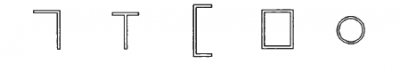

For smaller spans, tee sections are frequently used for chords, with angles used as internal members. The internal members may be bolted or welded to the tees. Back-to-back angles or channels may be used for longer spans or heavier loads, with a gusset plate used at nodes to connect the members.
For large trusses and heavy loads, typically found in transfer trusses in buildings, members may be rolled sections; typically UKC sections. Nodes are usually welded. Any necessary connections are completed with bolted splices within the length between nodes.
For many exposed trusses, hollow sections are chosen for their structural efficiency and for aesthetic reasons. Nodes will generally be welded in the workshop. As part of the truss design, it is essential to verify the resistance of the joints (in accordance with BS EN 1993-1-8[1]) as the joint design may dominate member selection and final truss geometry. Members should be selected carefully to avoid expensive strengthening of trusses fabricated from hollow sections.

[top]Types of connections

|

|
For all the types of member sections, it is possible to design either bolted or welded connections. Generally in steelwork construction, bolted site splices are preferred to welded splices for economy and speed of erection. Where bolted connections are used, it is necessary to evaluate the consequences of 'slack' in connections. In order to reduce these consequences (typically, the increase of the deflections), pre-loaded assemblies to produce non-slip joints are recommended.
Hollow sections are typically connected by welding whilst open sections are connected by bolting or welding, which will usually involve the use of gusset plates. Guidance on the design of welded joints for Celsius®355 and Hybox®355 hollow sections is available from Tata Steel.
Small trusses which can be transported whole from the fabrication factory to the site, can be entirely welded. In the case of large roof trusses which cannot be transported whole, welded sub-assemblies are delivered to site and are either bolted or welded together on site.
In light roof trusses, entirely bolted connections are less favoured than welded connections due to the requirement for gusset plates and their increased fabrication costs.
Profile shaping of tubular sections for joint fabrication
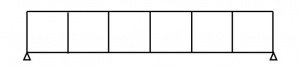
[top]Lateral stability
It is necessary to design members in compression against out-of-plane buckling. For simply supported trusses, the upper chord is in compression for gravity loading, and the bottom chord is in compression for uplift loading. For portal trusses, each chord is partly in compression and partly in tension.
Lateral restraint of the upper chord is generally given by the purlins and the transverse roof wind girder.
For the restraint of the bottom chord, additional bracing may be necessary, as shown below. Such bracing allows the buckling length of the bottom chord to be limited out of the plane of the truss to the distance between points laterally restrained; the diagonal members transfer the restraint forces to the level of the top chord, where the general roof bracing is provided.

|
Key Thick black dashes - two consecutive trusses Blue - The purlin which completes the bracing in the upper region |
It is possible to create a horizontal wind girder at the level of the bottom chords, with longitudinal elements to stabilize all the trusses.
[top]Design of wind girders
[top]Transverse wind girder
In general, the form of a transverse wind girder is as follows:
- The wind girder is arranged as a Warren or Pratt truss, parallel to the roof plane
- The chords of the wind girder are the upper chords of two adjacent vertical trusses. This means that the axial forces in these members due to loading on the vertical truss and those due to loads on the wind girder loading must be added together (for an appropriate combination of actions)
It is convenient to arrange a transverse wind girder at each end of the building so that the longitudinal members need act only in tension.
[top]Longitudinal wind girder
It is necessary to provide a longitudinal wind girder (between braced gable ends) in buildings where the roof trusses are not 'portalized'.
The general arrangement is similar to that described for a transverse wind girder:
- Warren or Pratt truss
- Generally, chord members will be provided from hollow sections
- The posts (if required) are the upper chords of the consecutive stabilized roof trusses.
[top]Guidance on global analysis
Although joints in trusses are often hardly pinned in reality, it is generally satisfactory (and encouraged by design Standards) to assume the joints are pinned and to verify the members for axial load only.
If loads are applied between nodes, trusses are often analysed with continuous chords, but with all internal members pinned. These assumptions about pinned joint behaviour apply to both bolted and welded connections.
Where member centre lines do not intersect at a node (the joint geometry may have been adjusted to increase the strength of the joint), the additional moments produced by the eccentricity are usually allowed for in the design of the chord members.
[top]Modelling
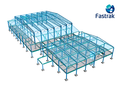

(Fastrak model courtesy of Trimble)
Several questions arise in respect of the modelling of a truss.
It is usually convenient to work on restricted models. For example, for a standard building, it is common and usually justified to work with 2D models (portal, wind girder, vertical bracing) rather than a global 3D model. A truss can be modelled without its supporting columns when it is articulated to the columns.
Nonetheless, it is important to note that:
- If separate models are used, it may be necessary, in order to verify the resistance of certain elements, to combine the results of several analyses; example: the upper chord of a truss also serves as chord of the wind girder.
- If a global 3D model is used and appropriate member releases not provided, 'parasitic' bending can be observed, which often only creates an illusory precision of the structural behaviour.
For trusses, two analysis models are commonly used, either:
- Continuous chords with pinned internals, or
- Pinned joints throughout the truss.
[top]The effect of non-preloaded assemblies on truss deflection
When the connections between elements which make up a truss are bolted, with bolts in shear and bearing (category A in BS EN 1993-1-8[1] ), the clearance introduced into these connections (which allows slip) can have a significant effect on displacement of the nodes.
In order to facilitate erection, the bolts are located in holes which are larger than the bolts themselves. For standard bolt sizes, holes which are 2 mm bigger than the bolt are usually made (usually referred to as a clearance hole).

In order for a connection with clearance holes to transmit the load, the bolt must come into contact with one or other of the connected parts which allows slip in the connection. For a connected tension member, this slip can be considered as an additional extension that is added to the elastic elongation of the member in tension. Likewise, for a connected compression member, the slip is considered as a reduction in length that is added to the elastic shortening of the compressed member.
The total slip in the many different connections of a truss structure can lead to a significant increase in displacements, which can have more or less serious consequences:
- In most of the cases, the visual effect is the worst consequence
- Increased deflection can lead to a reduction of free height under the bottom chord, which might prevent or upset the anticipated usage. For example, the additional deflection of a truss holding doors suspended in a gable of an aeroplane hangar could prevent the smooth operation of the doors
- Increase in the deflection can result in reduction in the slope of the supported roof and even, if the nominal slope were small, to a slope inversion; the risk of water ingress is increased.
It is therefore essential, where truss structures are concerned, to control the effect of connection slack on the displacements. In order to do this, it is often necessary:
- To use preloaded bolts (category B or C connections); or
- To use welded connections instead of bolted connections.
[top]Detailed design considerations for elements
Truss members are subjected to axial force, but may also be subjected to bending moments, for example, if the chords have been modelled as continuous.
[top]Verification of members under compression
The resistance of a member to compression is evaluated by taking into account the different modes of instability:
- Local buckling of the section is controlled using section classification
- Buckling of the member is controlled by applying a reduction factor to the resistance of the cross-section.
In most truss members, only flexural buckling of the compressed members in the plane of the truss structure and out of the plane of the truss structure need be evaluated.
The buckling resistance is obtained from BS EN 1993-1-1[2] by applying a reduction to the resistance of the cross-section. This reduction factor is obtained from the slenderness of the member, which depends on the elastic critical force.
For the diagonals and the verticals stressed in uniform compression the elastic critical force is determined from the buckling length of the member in accordance with BS EN 1993-1-1[2] Section 6.3.1.3 and according to Annex BB of BS EN 1993-1-1[2] :
- For buckling in the plane of the truss, the buckling length is taken equal to 90% of the system length (distance between nodes), when the truss member is connected at each end with at least two bolts, or by welding.
- For buckling out of plane of the truss beam, the buckling length is taken equal to the system length.
For buckling in the plane of the truss of the chord members in uniform compression, the buckling length may be taken as 90% of its system length (distance between nodes).
For buckling out of plane of the truss, the buckling length must be taken between lateral support points.
In the worked example, where the truss supports a roof, with purlins at the level of the upper chord of the truss:
- All the purlins connected to a roof bracing can be considered as lateral rigid support points.
- Intermediate purlins can also be considered as a rigid point of support, if the roof behaves as a diaphragm (class 2 construction according to BS EN 1993-1-3[3]).
- Lateral support points are provided to the lower chord by additional vertical bracing elements between trusses.
[top]Vierendeel trusses
[top]Use of Vierendeel trusses

Vierendeel trusses are rigidly-jointed trusses having only vertical members between the top and bottom chords. The chords are normally parallel or near parallel.
Elements in Vierendeel trusses are subjected to bending, axial force and shear , unlike conventional trusses with diagonal web members where the members are primarily designed for axial loads.
Vierendeel trusses are usually more expensive than conventional trusses and their use limited to instances where diagonal web members are either obtrusive or undesirable.
Vierendeel trusses are moment resisting. Vertical members near the supports are subject to the highest moments and therefore require larger sections to be used than those at mid-span. Considerable bending moments must be transferred between the verticals and the chords, which can result in expensive stiffened details.
[top]Analysis
As Vierendeel trusses are statically indeterminate structures, computer analysis software packages are generally used to analyse the truss.
[top]Connections
Vierendeel trusses have rigid joints which must transfer significant bending moments, especially near the supports. Welded joints are therefore common and may involve significant local reinforcement of the members at the joint. If joints are bolted, substantial connections will be necessary, generally using pre-loaded bolts.

|

|
[top]References
- ↑ 1.0 1.1 BS EN 1993-1-8:2005. Eurocode 3: Design of steel structures. Design of joints, BSI
- ↑ 2.0 2.1 2.2 BS EN 1993-1-1:2005+A1:2014, Eurocode 3: Design of steel structures. General rules and rules for buildings, BSI
- ↑ BS EN 1993-1-3:2006 Eurocode 3. Design of steel structures. General rules. Supplementary rules for cold-formed members and sheeting, BSI
[top]Further reading
- Steel Designers' Manual 7th Edition. Editors B Davison & G W Owens. The Steel Construction Institute 2012, Chapter 20, Trusses
- Architectural Design in Steel – Trebilcock P and Lawson R M published by Spon, 2004
[top]Resources
- Target Zero: Guidance on the design and construction of sustainable, low carbon warehouse buildings
- SCI P167 Architectural Teaching Resource. Studio Guide. SCI and Corus, 2003
- NCCI: Design of roof trusses SN027a-EN-EU
- Scheme Development: Conceptual design of truss and column solutions SS050a-EN-EU
- Example: Single span truss and post frame for a low pitch roof using battened section chords SX017a-EN-EU
- Single-Storey Steel Buildings Part 5: Joint design, The Steel Alliance
- Design of welded joints - Celsius®355 and Hybox®355, 2013, Tata Steel
[top]See also
- Single storey industrial buildings
- Cost of structural steelwork
- Operational carbon
- Target Zero
- Fabrication
- Welding
- Construction
- Preloaded bolting
- Steel construction products
- Simple connections
- Moment resisting connections
- Modelling and analysis
- Member design