


Thermal performance
The thermal performance of buildings is important in order to satisfy the Building Regulations, and the Code for Sustainable Homes in the residential sector. It is also important in order to achieve high BREEAM ratings in the commercial, educational and other sectors.
The UK Government has, through the Climate Change Act set a legally binding target to reduce national greenhouse gas emissions by at least 80% in 2050 from 1990 levels. In the UK's sixth Carbon Budget an even more optimistic target was set to reduce emissions by 78% by 2035 compared to 1990 levels. The operation of buildings currently accounts for a high percentage of the UK’s greenhouse gas emissions and therefore significant improvement in new and existing building performance is required if these targets are to be met.
One of the most effective ways of reducing operational energy consumption is by improving the thermal performance of the building envelope for commercial, industrial and residential buildings.
This article focuses on the thermal performance of single-storey buildings (including industrial, retail and leisure buildings) and addresses key issues associated with the building envelope. Thermal bridges within the thermally insulated layer of a building or at junctions in building envelopes occur in all forms of construction. A discussion of how these should be minimised as they add to the overall heat loss, is provided.

[top]Legislation
In the UK, new buildings must comply with Building Regulations. In England, the most commonly used method of meeting these regulations in the areas of thermal performance, energy use and operational CO2 emissions reduction is to follow the guidance given in Approved Document L. For new build the main documents, for England, are:
- Part L1 2021 – Conservation of fuel and power, Volume 1: Dwellings[1]
- Part L2 2021 – Conservation of fuel and power, Volume 2: Buildings other than dwellings[2]
For Wales (from 23 November 2022):
- Part L1 2022 – Conservation of fuel and power, Volume 1: Dwellings – for use in Wales[3]
- Part L2A 2014 – Conservation of fuel and power in buildings other than dwellings – for use in Wales[4]
In Scotland (from December 2022) the equivalent documents are:
- Technical Handbook 2022 - Domestic Buildings - Section 6: Energy[5]
- Technical Handbook 2022 - Non Domestic Buildings - Section 6: Energy [6]
For Northern Ireland:
- Technical Booklet F1 - Conservation of fuel and power in dwellings: June 2022 [7]
- Technical Booklet F2 - Conservation of fuel and power in buildings other than dwellings – June 2022[8]
And for Ireland:
- Technical Guidance Document L - Conservation of Fuel and Energy – Buildings other than Dwellings[9]
- Technical Guidance Document L - Conservation of Fuel and Energy – Dwellings[10]
Although these regulations set slightly different targets, they all use a similar methodology for setting those targets.
Part L2: 2021[2] includes the following limiting requirements:
- Primary energy use
- CO2 emissions rate
- U-values for planar elements
- airtightness
Guidance is also provided to reduce non repeating thermal bridges and to demonstrate that the building has appropriate passive control measures to limit solar gains.
[top]Energy/CO2 requirement

The main requirements in the UK are that:
- The primary energy use of the building must not be greater than the target primary energy rate
- The calculated CO2 emissions rate for the building (the Building Emissions Rate (BER)), must not be greater than the Target CO2 Emissions Rate (TER)
- For dwellings only, the fabric efficiency of the building must exceed the target fabric energy efficiency rate
The primary energy use and the BER is based on the annual energy requirements for the fixed building services (regulated energy), e.g. space heating, water heating and lighting, less the emissions saved by renewable energy generation technologies. Unregulated energy use is not considered.
The building and the target, for each of the three metrics above, must be calculated using one of the calculation tools included in the methodology approved by the Secretary of State for calculating the energy performance of the buildings. Those tools include:
- the Simplified Building Energy Model (SBEM) for those buildings whose design features are capable of being adequately modelled by SBEM; or
- other software tools approved under the Notice of Approval.
Guidance on the energy needs for heating and cooling is provided in BS BS EN ISO 52016-1[11], while energy requirements for lighting are given in BS EN 15193[12]. Approved dynamic simulation modelling software such as IES-VE or TAS produce a virtual model of the building. Standard operating conditions for each building type are defined in the National Calculation Methodology (NCM) and are applied to the building being assessed.
For residential buildings, the Dwelling primary energy rate, the CO2 Emissions Rate (DER) and the fabric energy efficiency are calculated using the Standard Assessment Procedure, a monthly energy balance methodology.
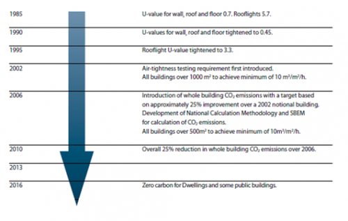
The most recent implementation of Approved Document L was in 2021. The history of changes to Approved Document L2[2] up to 2016 is shown.
[top]Factors affecting thermal performance
The operational CO2 emissions from a building are a function of the energy performance of the building and the fuel that is used to supply this energy. The energy performance itself depends on many aspects of the building design, such as the thermal efficiency of the building envelope, the availability of natural light and the type and efficiency of building services installed.
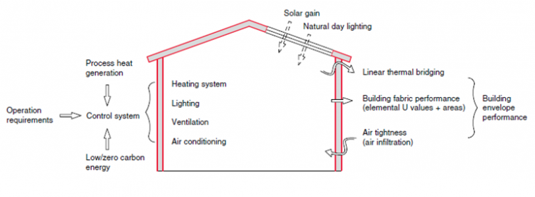

This article focusses on the thermal performance of the building envelope, which is a function of four characteristics:
- Fabric U-Values - the thermal performance of the planar elements, e.g. wall, roofs, windows
- Thermal bridging - the local heat losses that can occur around the planar elements and where the planar elements are penetrated by building components
- Airtightness - the ease at which air can pass through the envelope
- Rooflights/Daylighting.
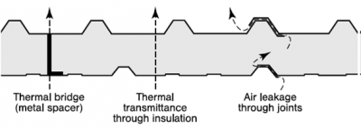
The first three characteristics are illustrated for a metal cladding system but are applicable for all types of building envelope.

[top]Fabric insulation
Increasing the building fabric insulation has often been the first approach taken when looking to reduce the thermal losses from a building. The designer needs to consider the implications of specifying a more highly insulated envelope, against the overall reductions in operational CO2 emissions which will be delivered. Recent studies, including Target Zero, have demonstrated that the cost effectiveness of reducing envelope U-values diminishes if they are reduced below current levels.
The U-value defines the thermal transmittance of a building envelope. This is the energy in Watts (W) passing through a square metre of construction per degree temperature difference from inside to outside. Maximum or limiting U-values are given in Approved Document L Volume 2[2] as well as Notional Building U-values that help to set the BER.
Increasing insulation thickness to lower U-values will reduce fabric losses from the building, but the benefits become proportionately less as the thickness is increased. U-values are already low, so the advantage of adding more insulation is limited and there are more cost effective ways of achieving whole building operational carbon reductions.
Limiting envelope U-values from Approved Document L Volume 2[2] and the values used for the Notional Building are shown.
| Element | Max area weighted average (Wm-2K-1 ) | Value used for notional building+ (Wm-2K-1 ) |
|---|---|---|
| Wall | 0.26 | 0.26 |
| Roof (flat/pitched) | 0.18/0.16 | 0.18 |
| Floor | 0.18 | 0.22 |
| Window, roof window, doors | 1.6 | 1.6 |
+NCM modelling guide November 2017
The relationship between U-value and insulation thickness is not linear. This relationship is shown for two common insulation materials. Actual cladding systems will vary due to factors such as repeating thermal bridging. It is important to consult the cladding manufacturer for the actual U-values of a particular system.
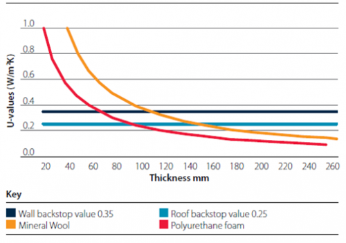

It can be seen that as one moves towards lower U-values, the graph begins to flatten out significantly. Specifying thicker, more highly insulated envelopes will therefore raise a number of issues including:
- Significant increase in cost
- Additional loads which the building structure must be designed to accommodate.
- Increased focus for built-up cladding systems on local thermal bridging through spacer systems and through fasteners.
- Increased weight of composite panels and associated handling issues
- Increased structural requirements on spacer bar systems.
These factors need to be considered and carefully balanced against potential capital cost increases and operational cost and CO2 reductions in the design of the U-values for the building envelope.
Reducing U-values will have a greater impact on the total heat loss and CO2 emissions of smaller buildings, and those with complex shapes, than for larger, simpler ones. This is due to the ratio of heated building volume to surface area. So, for typical industrial, warehouse or retail buildings, with relatively high volumes, increasing insulation has much less effect than in small buildings.
[top]Calculating U-values

U-values for the planar elements of the envelope system can be calculated numerically using the principles and methodologies generally set out in BS EN ISO 6946[13] and BRE 443[14]. Specific guidance is given for light steel framing and light steel infill walling in BRE 465[15], for built-up cladding in SCI P312 and for composite panels in BS EN 14509[16].
Otherwise, U-values for more complex systems not covered by the guidance above must be calculated using a numerical model thermal transmittance analysis to model heat transfer in 2D or 3D across the planar elements from inside to outside the building detail or whole building construction. Guidance is published by the Metal Cladding and Roofing Manufacturers Association (MCRMA)[17].
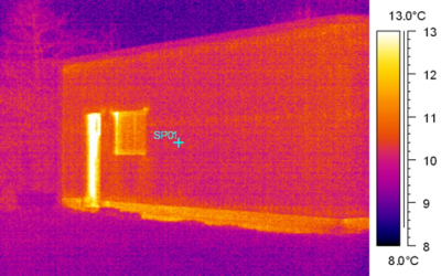
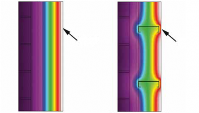
The effect of repeating thermal bridges is included within the calculated U-values for the envelope system. The thermal image shows the effect of repeating thermal bridging (in this case steel studs) on the thermal performance of the building envelope. With the steel studs the internal surface temperature is lower and the heat transfer across the wall higher than without.
[top]Thermal bridging
Thermal bridges occur where the envelope is penetrated by a material with a significantly higher thermal conductivity than the surrounding materials, and at interfaces between building elements where there is a discontinuity in the insulation. Thermal bridges result in local heat losses, consequently more energy is required to maintain the internal temperature of the building and lower internal surface temperatures can be found around the thermal bridge. Cold surface temperatures can cause condensation which may lead to mould growth.
Local heat losses caused by thermal bridges become relatively more important, as the thermal performance, i.e. U-values, of the planar elements of the building envelope are improved.
Thermal bridges can be classified as:
- Repeating thermal bridges - where bridges occur following a regular pattern, such that made by wall ties penetrating a cavity wall
- Non-repeating thermal bridges - such as the bridging of a cavity wall by a single lintel
- Geometrical thermal bridges - placed at the junction of two planes, such as at the corner of a wall.
Repeating thermal bridges, such as wall ties, wall studs and mortar joints are accounted for in the U-value calculation for the planar elements as discussed above and in BRE 497[18] and SCI P312. Therefore, heat losses through these regular local thermal bridges do not need to be considered in addition to the heat loss through the planar element.
Thermal bridges in building envelopes may be caused by:
- Geometry, e.g. at corners which provide additional heat flow paths
- Building envelope interfaces, e.g. window sills, jambs and headers
- Structural interfaces, e.g. floor to wall junctions, eaves
- Penetration of the building envelope, e.g. balcony supports, fixings and structural elements
- Structural considerations, e.g. lintels, cladding supports
- Poor construction practice, e.g. gaps in insulation, debris in wall cavity.
The additional heat loss through a linear thermal bridge is defined by its linear thermal transmittance (ψ) with units of Wm-1K-1, or the rate of heat flow per degree temperature difference per unit length of the junction.
For example, the junction of wall and floor can be defined by a linear length, i.e. for one façade of a building this will be the building length. Due to the detailing of this junction heat loss through this area may be higher than through the planar elements of wall and floor. The ‘extra’ heat loss here is given by the linear thermal bridge, ψ, and if this value is 0.1Wm-1K-1, and the width of the building is 10m then the additional heat loss due to this junction is one Watt per degree Kelvin temperature difference from the interior to exterior.
Thus additional heat loss is dependent upon the type of detail, the thermal conductivity of the cladding materials and the quality of the detail design and installation.
[top]Thermal bridging in the Building Regulations
Approved Document L Volume 2[2] places specific emphasis on the performance of building details and the additional heat losses through linear thermal bridging; it states that: The building fabric should be constructed to a reasonable quality so that the insulation is reasonably continuous over the whole building envelope.
Reasonable provision for the avoidance of thermal bridging can be achieved by designing and building details to the standards set out in BRE IP 1/06[19] and MCRMA TP 17[20], or with equivalent performance.
Provided that the above criterion has been met, the actual ψ-value entered into the calculation for the BER depends on the path chosen:
- A person with suitable expertise, using the methods set out in BRE 497[18] should calculate the ψ-value using appropriate software, and this value used in the BER calculation.
- Where no thermal bridging calculations are carried out. The values given in the BRE IP1/06[19] should be increased by 0.04W/mK or 50%, whichever is greater, before being used in the BER calculation.
It can be seen that there is an increased penalty for the use of details with a lesser degree of accurate assessment of performance and this will make the building less likely to comply with the Approved Document[2].
For dwellings, Accredited Construction Details may be used. These are a range of published details have been published for England & Wales that have been designed to have linear thermal transmittance values that do not exceed the values given in BRE IP 1/06[19].
Accredited Construction Details for Scotland are also available.
[top]Steel and thermal bridging


Steel has a high thermal conductivity compared with many other construction materials. The high thermal conductivity means that steel construction systems, both the structural frame and cladding, must be carefully designed to minimise unwanted heat flows. For example, built up cladding systems and composite cladding panels with steel skins are designed to keep thermal bridging to a minimum by ensuring that steel elements are not continuous through the cladding e.g. for a built up cladding system as shown in the figure below a thermal break is provided beneath the bracket in the spacer system.
| Material | Thermal conductivity, λ (Wm-1K-1 ) |
|---|---|
| Steel | 45 to 50 |
| Stainless steel | 15 to 17 |
| Insitu normal weight concrete | 1.7 to 2.2 |
| Brickwork | 0.6 to 0.8 |
| Gypsum-based board | 0.16 to 0.22 |
| Plywood | 0.12 to 0.15 |
| Mineral wool insulation | 0.03 to 0.04 |
| Closed cell insulation | 0.02 to 0.03 |
Source: CIBSE Guide A[21]
[top]Quantifying the effects of thermal bridging
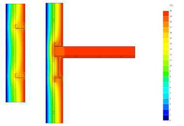

Analysis of the thermal performance of details is usually undertaken by building a 2D or 3D computer model and applying a thermal transmittance numerical analysis to this model. This calculates the heat flow across this detail that is in excess to the normal heat loss through the planar elements. This numerical modelling must be done according to the methods set out in BS EN ISO 6946[22] or BS EN ISO 10211[23] and using software that has been developed in accordance with these standards. Further information on modelling thermal bridging in construction specifically involving metal cladding can be found in MCRMA Technical Paper 18[17], while guidance on thermal bridging for steel construction is provided in SCI P410 and for light steel framing and modular construction in SCI P411.
The basic methodology to calculate the extra heat loss at a junction, over and above the heat loss through the planar elements, is to produce two models, one with and one without the junction under consideration. Then the predicted heat loss from inside to outside of these models is calculated (see below). The difference between these calculated values is considered the thermal bridging value or Ψ-value for this junction. The units for this are Wm-1K-1 and the value represents heat loss in Watts per linear metre of the junction per degree Kelvin temperature difference from inside to outside.
This methodology is shown mathematically in the equation below; the left-hand function representing the heat loss through the junction with the thermal bridge and the right-hand side being the heat loss through an equivalent length of the planar envelope. Thus the Ψ-value is the difference between the two:

Where:
Q = Heat loss in W from the model with the junction under consideration
W = Junction width in m
Ti = Internal air temperature in K
Te = External air temperature in K
UA = U-value of panel without the junction in Wm-2K-1
Ljunction = Junction length in m
See BRE 497[18] for various examples of calculating the linear thermal transmittance.
Numerical modelling software packages available to analyse thermal bridges include BISCO (2D) & TRISCO (3D), PSI-THERM, HEAT 2 (2D) & HEAT 3 (3D) and Ansys.
[top]Structural members penetrating the envelope
For some buildings there may be situations where structural steel elements penetrate the insulated envelope, e.g. canopies and roof members, or where they are fixed to other steel components, such as balcony brackets and brick support units. These areas require careful consideration to minimise thermal bridging. Further information and guidance is provided in SCI P380.
There are three ways of reducing thermal bridging in steel construction:
- Eliminate the thermal bridge by keeping the steelwork within the insulated envelope
- Locally insulate any steelwork that penetrates the envelope
- Reduce the thermal transmittance of the thermal bridge by using thermal breaks, changing the detailing or by including alternative materials.
Keeping the steelwork within the insulated envelope of the building is the preferred means to eliminate a thermal bridge. However, there will be situations where the steelwork has been detailed to penetrate the envelope for a reason.
An example of how to eliminate a thermal bridge, or at the very least minimise the extent of thermal bridging, is shown by the two following example cases. Figure (a) shows balconies supported by the structural frame of the building; this requires significant structural connections thereby creating a strong thermal bridge. Figure (b) shows an alternative, where balconies are supported independently; this requires considerably less connection to the building and the effect of thermal bridging is significantly reduced.
- Balcony support options
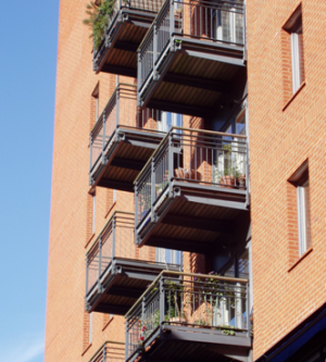
(a) Balconies supported from the structure
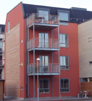
(b) Independently supported balconies


[top]Local insulation


Where a steel member penetrates the insulated envelope of a building, insulation may be provided around the element to lengthen the heat flow path, thereby, reducing heat losses and raising the internal surface temperature of the element. Additional insulation can be applied on either the internal or external side of the building envelope. A beam is shown with local internally applied insulation.
The amount of insulation required in terms of thickness and length along the beam will depend on the particular circumstance and can be determined with the aid of thermal modelling. Factors to be considered include: the size of the member, the U value of the building envelope and the internal conditions of the building (temperature and humidity).
A typical solution is to insulate the steel beam for a length of 1.2m with 50mm thick rigid insulation. Conveniently, most rigid insulation boards are supplied 1.2m wide. Placing insulation on the internal side of the beam will reduce the temperature of the insulated part of the beam. Therefore, it is essential that a vapour control layer is applied around the outside of the insulation to prevent condensation. Boards with factory applied facings can be used to provide vapour control. Specialist adhesive tapes can be used to seal joints and edges.
[top]Reducing thermal transmittance


The thermal transmittance of a thermal bridge can be reduced by using thermal breaks, changing the detailing or by including alternative materials.
Thermal breaks may be provided by inserting a material with a low thermal conductivity between elements with higher thermal conductivities, as illustrated. Reducing the cross sectional area of an element can also be used to reduce its thermal transmittance where it bridges an insulated building envelope.
Thermal breaks are provided in certain manufactured elements, such as metal window frames and composite cladding panels, where the steel skins are separated at junctions by a layer of insulation and in built up cladding systems where thermal break pads can be provided beneath brackets. Similarly, thermal break pads can be provided behind the brackets of brickwork support systems. The brackets of brickwork support systems are made from stainless steel primarily to resist corrosion but this has the added benefit of reduced thermal bridge because stainless steel has a lower thermal conductivity than carbon steel.
Where structural forces are transferred through steel elements that pass through the insulated building envelope, such as in balcony connections, brickwork support systems and roof structures, the form of break must be considered carefully. It is vital to ensure that the structural performance remains acceptable. Materials used for thermal breaks will generally be more compressible than steel. Therefore, deflections, as well as strength, should be checked when thermal breaks are used.
Pads and spacers of high thermal resistance can be made from a range of materials such as PTFE, polyethylene and synthetic resin bonded fabric. Proprietary solutions are also available to provide structural thermal breaks. These include thermal breaks using a layer of PTFE bolted between beam end plates and using a proprietary solution bolted between beam end plates.
- Isokorb thermal break
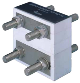
Isokorb thermal break unit
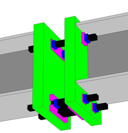
Thermal model of an Isokorb unit


Further information and guidance is provided in SCI P380.
[top]Control of condensation
Although heat loss is a very important effect of thermal bridging, the more potentially serious aspect as far as building occupiers are concerned arises from the occurrence of low internal surface temperatures in the region of the thermal bridge. Low surface temperatures can lead to surface condensation if they are below the dew point of the air. For non absorbent surfaces, condensation can cause unsightly collection of moisture and dripping/pooling on surfaces beneath. For absorbent materials such as insulation products or plasterboard, interstitial condensation can occur, leading to loss of thermal performance and/or structural integrity and mould growth. The local relative humidity need only be sustained at above 80% for mould growth to accelerate.
BS 5250[24] and BS EN ISO 13788[25], describe the causes and effects of surface and interstitial condensation in buildings and gives recommendations for their control. Further information on condensation due to thermal bridging is provided in BRE IP 1/06[19]. An indicator of condensation risk is provided by the temperature factor fRsi. This factor is given by the following equation in the BRE IP 1/06[19]:
fRsi= (Tsi - Te)/(Ti - Te)
where:
Tsi is internal surface temperature (from thermal modelling)
Te is external air temperature
Ti is internal air temperature.
Minimum recommended values of fRsi, termed critical temperature factors fCRsi, are given in BRE IP 1/06[19] and are reproduced in the table. The critical temperature factors depend upon the building use and the consequent internal relative humidity of the building. The higher the likely internal humidity, the higher the critical temperature factor will be to eliminate the likelihood of condensation.
| Type of building | fCRsi |
|---|---|
| Storage buildings | 0.30 |
| Offices, retail premises | 0.50 |
| Dwellings, residential buildings, schools | 0.75 |
| Sports halls, kitchens, canteens | 0.80 |
| Swimming pools, laundries, breweries | 0.90 |
[top]Airtightness

The airtightness of a building is central to the requirements of Part L of the Building Regulations and is likely to become even more important as architects strive to improve the thermal performance of the building envelope without significant increases in insulation thickness.
Airtightness is a measure of the uncontrolled airflow into and out of the building. If a building is not designed well, or built without due consideration for sealing joints, it can lose a large amount of heat to the outside through uncontrolled ventilation.
The airtightness of a building is quantified in terms of its air permeability, which is defined as the volume flow rate of air per square metre of building envelope and floor area at a given pressure, usually 50Pa.
Focussing on increased airtightness can offer a good opportunity for reducing heat loss through the building envelope. To maintain a good working environment within a building, a number of air changes per hour are necessary, dependent on activity levels. Best practice dictates that the building envelope should be as airtight as possible, with controlled ventilation. For more information, see Creating an air-tight building envelope
[top]Airtightness Regulation
The airtightness of a building is one of the variables that is fed into the whole building CO2 calculation tool, usually SBEM, that predicts whether the building will meet the requirements set out in Section 5.13 of Approved Document L2A[2]. It is advantageous therefore to have a low design air permeability.
For buildings over 500m2, Approved Document L2A[2] states that a maximum reasonable design limit for airtightness is an air permeability value of 10 m3/h/m2 at 50Pa. All new non-domestic buildings with a floor area greater than 500 m2 must be pressure tested.
Although a limit of 10 m3/h/m2 is given as a limit, the Notional Building in Approved Document L2A[2] uses a figure of 3 to 7 m3/h/m2 (depending on the building size and whether it is side or top-lit) to set the Target Emission Rate (TER) and this may be seen as a sensible design value, particularly for large buildings.
[top]Airtightness Testing Procedure
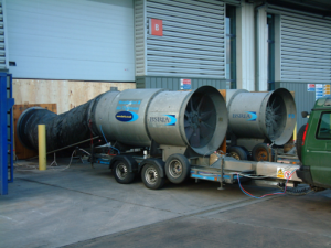

(Image courtesy of BSRIA)
In order to test the airtightness of a building it is over or under-pressurised with respect to atmospheric pressure by the use of large fans. The volume of air required to maintain this pressurisation is recorded and the air leakage at 50Pa (Q50) (in m3 per hour) is calculated. Air permeability is then defined by:
Air Permeability = Q50/SA
Where SA = area of external envelope including the floor (m2)
- Testing must be carried out by member of The Airtightness Testing and Measurement Association (ATTMA)
- The test must be carried out in accordance with the relevant ATTMA Technical Standard[26] and BS EN ISO 9972[27]
[top]Potential air leakage paths
Pre-finished steel cladding is inherently air-tight. The management of the interfaces between the cladding sheets is critical to ensure a high performance building envelope. When designing a building it is important to consider the location of the air tight barrier and design the cladding such that this is maintained as a continuous layer with as few breaks as possible. The following interfaces should be considered:
- Metal cladding side and end lap joints.
- The interface between metal cladding and pre-fabricated flashings at building corners, ridges, eaves and verges.
- The interface between metal cladding and the floor slab/dwarf wall and other building envelope materials.
- Unplanned penetrations in the cladding.
Experience has shown that with close attention to detail, steel-clad buildings should have no difficulty in achieving air-leakage rates of no more than 5m3/h/m2, and often even less than 3 m3/h/m2. However, air-leakage is highly dependent on building geometry. Simple, large buildings have proportionately less potentially-leaky interfaces than more complex, small ones.
[top]Achieving airtightness
In a typical pre-finished steel-clad building, the airtightness barrier is provided by the interior (or ‘liner’) side of the envelope. While the outer sheet of an insulated envelope will provide weather protection, and will be sealed in order to prevent water leaks, it is important that it is not relied upon for airtightness. This is for two main reasons:
- The insulation cavity on a build up system is slightly ventilated to allow air movement and so eliminate condensation build up in the cavity.
- Sealing at the liner side will prevent water vapour from inside the building penetrating the insulation.
The first step in constructing an air-tight building is to identify the liner as the airtightness barrier and ensure this is focused on during the design and construction of the building envelope.
The means of achieving airtightness for a building using a built-up, insulated, pre-finished steel cladding system will be different from one clad with factory insulated composite panels. Both systems can provide extremely good airtightness, using good detailing and construction.
[top]Built-up systems
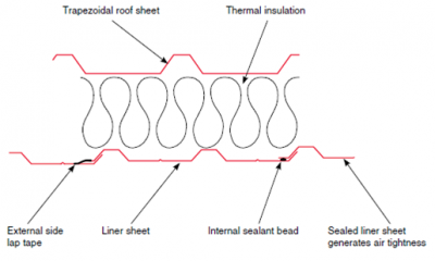

Airtightness for built-up systems is generated by the liner sheet. Sealant tapes or beads are used to seal the overlap joints between adjacent sheets. It is normal practice to have a slightly vented insulation cavity to reduce condensation risks. The external or weather sheet of the building envelope does not normally contribute to airtightness.
Side lap joints are formed where the profiled edge of one sheet overlaps the edge of the adjacent sheet. Liner sheets are normally 0.4mm or 0.7mm thick. The joint is sealed either using a sealant bead, which is placed inside the overlap joint, or an external tape, which is placed over the joint line on the cavity side of the liner sheet. The joint can be reinforced with stitcher screws or rivets. This is a requirement for most firewall constructions. Cladding system manufacturers should be consulted for the recommended size and grade of sealant beads.
Side lap joints account for approximately 75% of joint length in the cladding. There is approximately 1m of joint for every square metre of cladding; depending on the sheet cover width. For this reason, effective sealing of this joint provides the basis of an air-tight cladding system.
Further information on airtightness sealing techniques for other generic built-up envelope system joints are given in the publication, Creating an airtight building envelope.
[top]Factory insulated composite panels
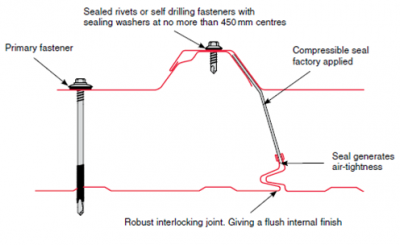

Airtightness is achieved by the compression of factory fitted seals on the liner side of the joint. Sealant fitted on the outer sheet is for weather tightness only. Care must be taken to ensure that condensation does not occur inside the joint. The position of the factory filled seals will be specific to the individual panel. For further information on seal position and potential condensation contact the cladding system manufacturer.
Further information on sealing envelope joints is given the publication, Creating an airtight building envelope.
[top]Rooflights/Daylighting
Lighting accounts for 20 to 25% of all electricity consumed in Northern Europe. Typically industrial and commercial buildings consume 20 to 30% of their total energy just for lighting.
Rooflights can readily be incorporated into a pre-finished steel roofing system. The main advantage of increasing the rooflight area is to reduce the energy used for lighting. However for any building, there will be a point where this improvement will be negated by the increased requirement for space heating, since rooflights allow more heat to escape than opaque roof cladding elements.
[top]Lighting levels
It is generally accepted that a degree of natural lighting will enhance the working environment. The colour and reflectivity of the internal surface of the walls and roof will affect the internal illuminance. Use of a ‘bright white’ pre-finished steel liner sheet will provide an excellent internal surface finish for general lighting requirements.
The following table, from CIBSE Guide A[21], gives some general guidelines for recommended illuminance levels for different activities:
| Standard maintained illuminance (lux) | Activity / interior |
|---|---|
| 200 | Foyers, entrances, automated processes |
| 300 | Libraries, sports halls, food court packing, warehouses |
| 500 | General offices, assembly, retail shops |
| 750 | Drawing office, supermarkets, showrooms |
| 1000 | DIY superstore |
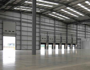
[top]Provision of daylight in large single storey buildings
There are two options for providing daylight to the interior of large single storey buildings:
High-level vertical glazing elements
Known as clerestory glazing within the exterior walls. The glazing ratio is limited by the proportionally low area of wall, in relation to roof area. Their main disadvantage is the rapid decay in natural lighting (daylight factor) with distance from the window, an important consideration given the deep plan nature of many buildings. For this reason, they are not suitable for multi-bay buildings. Positioning of high bay racking or bulky equipment will also obstruct natural light penetration from the sides. Daylight quality and quantity is highly dependent upon orientation of the building. Large areas of vertical glazing can also result in localised solar gains and can make some kinds of work difficult.
Rooflights
Consisting of translucent elements within the roof cladding construction, through which natural daylight can be well distributed, with little dependence upon orientation at low roof pitches. There is a wide range of rooflight types and constructions, which are dependant on the choice of cladding system, but these fall into two categories:
- In-plane where the rooflight is profiled to match the roof cladding. This is the predominant design used with pre-finished steel cladding on portal framed buildings. These are generally manufactured from Glass Reinforced Polyester (GRP), Poly Vinyl Chloride (PVC) or Polycarbonates. The thickness varies from 1mm to 3mm dependant on the material used and the structural requirements.
- Out-of-plane which include barrel vault and domed designs. These are designed to sit above the roof level. They are fixed to a kerb or upstand, which is attached to the cladding. The upstand must be insulated but will introduce some additional heat losses. This type of rooflight is generally only used on membrane or standing seam type roofs where in plane rooflights are not possible.
Out-of-plane lights are generally more expensive, provide less light and generate more potentially problematic interfaces.
Rooflights are generally constructed as double or triple skin arrangements and can either be fabricated on site or preassembled in a factory. In practice most rooflights will need to be triple skin to achieve the limiting U-value standard of 2.2 W/m2K as specified in Approved Document L[2]. Lower U-values are available with some systems. Surface coatings can be applied to the rooflights to improve durability and reduce build up of dirt, which would otherwise reduce the level of light transmittance.
It should be noted that the lighting design level has a major impact on the energy consumption and resultant CO2 emissions. This is discussed in detail in the Target Zero design guides for the retail and warehouse buildings. For low energy design, the lowest sensible lighting level should be specified. A practical approach is to specify a low level of background lighting which can come mainly from windows or rooflights, with localised ‘point’ lighting in areas where higher illuminance is required.
[top]Use of rooflights
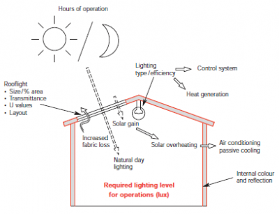

When considering the percentage rooflight area for a building, the designer will need to look at the interaction of a number of conflicting requirements and aim to achieve a balance, which satisfies the building operations and regulatory requirements as well as minimising overall energy usage.
The positive effects of increased level of rooflights are:
- Provision of natural daylight
- Reduced CO2 from lighting
- Solar heat gains in winter.
The negative effects are:
- Increased fabric heat losses
- Excessive solar gains and overheating during summer
- Cost of installation
- Increased maintenance requirement.
In practical terms for large single storey buildings, 10% rooflight area can be considered as a good starting point when considering a daylighting requirement. The optimum range of rooflight area, in terms of overall operational carbon emissions, is usually accepted to be in the range 10% to 15%.
The hours of operation of the building can have a significant impact on the usefulness of rooflights. At night, rooflights release more heat through conduction than opaque roof elements and therefore the more hours of darkness during which the building is in operation, the lower the optimal rooflight area will be.
Where appropriate, detailed dynamic thermal modelling, that is not constrained by the requirements of the NCM, should be undertaken to determine an optimum rooflight area.
[top]Specifying rooflight layout
The arrangement of rooflights should aim to give an even distribution of light. In some circumstances additional or reduced areas of rooflight could be considered for areas of different activity within the building. However, this approach could cause issues if there is a future change of use of the building, so in general, rooflights are generally distributed with relative uniformity over the roof area.
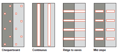

There are four general approaches for installation of rooflights:
- Chequerboard
- Continuous
- Ridge to eaves
- Mid-slope.
Rooflights are significantly more fragile than pre-finished steel cladding. Even when specified as ‘non fragile’ it is wise to design the roof so that it is not necessary to walk over them. This consideration must be taken into account when specifying the layout and would generally discount the 'continuous' and 'ridge to eaves' arrangements. In all cases the designer should ensure that the position of rooflights is obvious throughout the life of the building, taking account of any colour fade/ discolouration, which may occur. It is common practice to use brightly coloured fasteners around rooflights to ensure their visibility. For further information regarding safety practices for work on roofs and rooflights, refer to ACR(CP)001[28].

The supplied and installed cost of rooflights vary greatly dependant on type and ease of installation. As a general guideline, in-plane rooflights will cost in excess of double the price of a similar area of insulated pre-finished steel cladding. For this reason, it is economically sensible to specify the minimum area of rooflights, which will give the majority of the daylighting benefits.
Out-of-plane rooflights are significantly more expensive and are far more complex to install. This must be taken into account when comparing the overall costs of a profiled metal roof with in-plane rooflights against other constructions, such as flat roofs, which require out-of-plane rooflights.
As rooflight area increases, there are diminishing returns on natural lighting, combined with increasing risk of solar overheating. The optimum area will depend on a number of factors.
In general a mid-slope approach offers the most practical solution with a good balance between an even distribution of natural light, without the increased number of potentially problematic interfaces created by a chequerboard layout and maintains easy access over the entire roof structure for maintenance, unlike ridge to eaves and continuous arrangements.
[top]Solar gain and overheating
In addition to letting beneficial daylight into the building, rooflights also transmit infrared radiation, which generates heat within the building. This process is referred to as ‘solar gain’. In winter, solar gains can provide additional heat which can reduce the peak heating load, however solar gains need to be managed to prevent overheating during summer periods. Overheating can result in increased ventilation requirements or high air conditioning loads which will significantly increase energy demand and resultant CO2 emissions to maintain a comfortable working environment.
Approved Document L[2] requires that reasonable provision for limiting solar gain is made by demonstrating that for each space in the building that is either occupied or mechanically cooled, the solar gains through the glazing, from April to September, are no greater than would occur through a reference glazing system. For every space that is toplit (as defined by the NCM) and not greater than 6m high, the reference case is a horizontal roof of same total area that is 10% glazed.
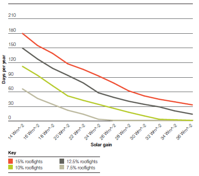
[top]Effect of rooflight area on solar gain
The solar gain for increasing percentage rooflight area for a single storey building (plan area 3000m2) is illustrated below. It shows the number of days in a year when the solar heat gain will reach a given value. The data presented is for 7.5%, 10%, 12.5% and 15% rooflight area.
For a building with over 10% rooflight area, there is an increasing risk of solar overheating. The additional effects of internal process heat gains should also be taken into account and must be added to the solar heat loads.

[top]References
- ↑ Approved Document L1, 2021, Conservation of fuel and power, Volume 1: Dwellings. Department for Levelling Up, Housing and Communities
- ↑ 2.00 2.01 2.02 2.03 2.04 2.05 2.06 2.07 2.08 2.09 2.10 2.11 2.12 2.13 Approved Document L2, 2021, Conservation of fuel and power, Volume 2:Buildings other than dwellings. Department for Levelling Up, Housing and Communities
- ↑ Approved Document L1, Conservation of fuel and power, Volume 1: Dwellings, 2022 – for use in Wales. Welsh Government
- ↑ Approved Document L2A,(Conservation of fuel and power (New buildings other than dwellings) 2014 Edition incorporating 2016 amendments. Welsh Government
- ↑ Building standards technical handbook: 2022 - Domestic Buildings, Section 6: Energy, The Scottish Government
- ↑ Building standards technical handbook: 2022 - Non Domestic Buildings, Section 6: Energy, The Scottish Government
- ↑ Technical Booklet F1 - Conservation of fuel and power in dwellings: June 2022, Department of Finance (NI)
- ↑ Technical Booklet F2 - Conservation of fuel and power in buildings other than dwellings – June 2022, Department of Finance (NI)
- ↑ Building Regulations: Technical Guidance Document L Conservation of Fuel and Energy – Buildings other than Dwellings, Department of Housing, Local Government and Heritage, 2021
- ↑ Building Regulations: Technical Guidance Document L Conservation of Fuel and Energy – Dwellings, Department of Housing, Local Government and Heritage, 2021
- ↑ BS EN ISO 52016-1:2017 Energy performance of buildings. Energy needs for heating and cooling, internal temperatures and sensible and latent heat loads. Calculation procedures, BSI
- ↑ BS EN 15193-1:2017 Energy performance of buildings. Energy requirements for lighting. Specifications, Module M9, BSI
- ↑ BS EN ISO 6946:2017. Building components and building elements – Thermal resistance and thermal transmittance – Calculation method. BSI
- ↑ BRE 443, 2006, Conventions for U-value calculations, Building Research Establishment
- ↑ BRE 465, 2002, U-values for light steel frame construction, Building Research Establishment
- ↑ BS EN 14509:2013. Self-supporting double skin metal faced insulation panels – Factory made products – Specifications, BSI
- ↑ 17.0 17.1 MCRMA TP 18, 2006, Technical Paper 18 – Conventions For Calculating U-Values, f-Values And Ψ-Values For Metal Cladding Systems Using Two- And Three Dimensional Thermal Calculations. MCRMA
- ↑ 18.0 18.1 18.2 BRE 497, 2016. Conventions for calculating linear thermal transmittance and temperature factors.
- ↑ 19.0 19.1 19.2 19.3 19.4 19.5 BRE IP 1/06, 2006, Assessing the effects of thermal bridging at junctions and around openings, Building Research Establishment
- ↑ MCRMA TP 17, 2007, Technical Paper 17 – Design guide for metal roofing and cladding to comply with energy requirements of UK Building Regulations, MCRMA and EPIC
- ↑ 21.0 21.1 CIBSE Guide A: Environmental Design 2015 (reprinted with corrections Feb 2016)
- ↑ BS EN ISO 6946:2017 Building components and building elements - thermal resistance and thermal transmittance - calculation method. BSI
- ↑ BS EN ISO 10211:2017, Thermal bridges in building construction – heat flows and surface temperatures – detailed calculations. BSI
- ↑ BS 5250:2011+A1:2016. Code of practice for control of condensation in buildings. BSI
- ↑ BS EN ISO 13788:2012. Hygrothermal performance of building components and building elements – Internal surface temperature to avoid critical surface humidity and interstitial condensation – calculation methods. BSI
- ↑ Technical standard L2, Measuring air permeability of building envelopes (Non Dwellings), 2010, Air Tightness Testing and Measurement Association
- ↑ BS EN ISO 9972:2015. Thermal performance of buildings – determination of air permeability of buildings – fan pressurisation method, BSI
- ↑ ACR(CP) 001: 2016 Rev5 Recommended Practice for Work on Profiled Sheeted Roofs (orange book)
[top]Resources
- SCI P312, Metal cladding: U-value calculation: assessing thermal performance of built-up metal roof and wall cladding systems using rail and bracket spacers
- SCI P346, Best practice for the specification and installation of metal cladding and secondary steelwork
- SCI P380, Avoidance of thermal bridging in steel construction
- SCI P410, Thermal bridging in steel construction
- SCI P411, Thermal bridging in light steel framing and modular construction
- SN06, 2006, Achieving airtightness with metal cladding systems, Steel Industry Guidance Notes
- SN47, 2010, Thermal Performance, Steel Industry Guidance Notes
- SCI EP37 Best Practice in Steel Construction – Industrial Buildings, Guidance for architects, designers & constructors
- Guidance document GD 24 – Installation of purlins and side rails, MCRMA, January 2016
Colorcoat® Technical Papers:
[top]See also
- Facades and Interfaces
- Building envelopes
- Target Zero
- Infill walling
- Single storey industrial buildings
- Operational carbon