


The Noel-Baker School, Alvaston, Derby
Introduction

In a school the most usual and important source of dynamic excitation is pedestrian traffic. A person walking at a regular pace (between 1.8-2.2 Hz) applies a periodically repeated force to the floor, which can cause a build-up of response. In a school where these activities predominate, the structure should not only be sufficiently strong but also comply with comfort and serviceability criteria[1][2]. It was therefore necessary to perform a floor vibration assessment to show that the occupied floors achieve a minimum natural frequency of 4.0 Hz and a maximum response factor of R=8 for normal walking excitation.
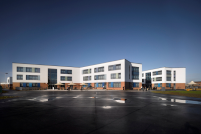
The Noel-Baker School development involved the rebuilding and co-location of Noel-Baker School, a mainstream secondary school with St Martins School, a special education school. As part of the Building Schools for the Future (BSF) Programme this £40m new-build project in Derby opened in September 2012 and accommodates the 1,150 pupils from the Noel-Baker school and the 90 pupils from St Martin's special school.
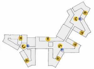
The school accommodation is arranged in butterfly shaped clusters and embraces open plan, together with shared facilities including a sports hall, a fitness suite and a dance studio.
The school building comprises a two-storey steel frame with floors supported by a grid of steel columns and supporting steel beams. Owing to the butterfly plan shape of the building and its non-orthogonality, the grid size varies significantly. Maximum column grids of 8m x 7m are typical with beams that act compositely with the floors. The floor slabs comprise:
- Pre-cast concrete planks with Ultra Shallow Floor Beams (USFB) and structural topping,
- Re-entrant steel deck floor slab with in-situ poured concrete

The Pre-cast concrete planks are 250mm in depth and span up to a maximum of 8m. The planks are positioned within the depths of the USFB’s to minimise floor depths. USFB’s vary in depth depending on their span but typically for the larger spans use structural tee combinations of UKB’s and UKC’s up to sizes of 610UKB’s and 356UKC’s. Structural topping with a thickness up to 115mm makes up the completed floor assembly.
In areas where floor spans are typically between 2-4m, 140mm thick composite slabs using 50mm deep re-entrant steel decks are used.
Floor vibration assessment
The modelling techniques presented in SCI publication P354[3] were used to model the school . The complete structure comprising the building main frame and floors were modelled using the ANSYS finite element package.
The 140mm deep composite decking floor slabs were modelled using 89 mm thick shell elements, which is the depth of the concrete above the re-entrant deck. The density of the concrete material was also adjusted to take account of the additional concrete in the troughs of the profile. The stiffness was modified in one direction to represent the troughs of the deck. These shell elements were, in turn, connected to the nodes of the beam elements.
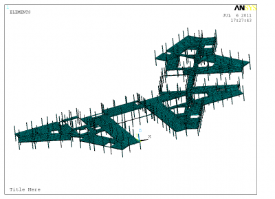

The beams were modelled using offset beam elements with rigid beam-to-column joints (although joints are designed to be pinned, for floor vibrations the strains are not large enough to overcome the friction and so pinned joints may be treated as fixed). The columns were pinned at their assumed inflexion points, located mid-height between the floors, where it is assumed that the edges of the floor are restrained from vertical and horizontal motion, but not from rotation. The meshed model is shown right.
The finished floor was analysed under the permanent loads (self-weight and superimposed dead load from the ceilings and services) plus 10% of the imposed floor loads. The level of damping was assumed to be 3.0%, which corresponds to a fully fitted-out and furnished floor in normal use.
Current standards describe human discomfort in terms of the perceived acceleration of the floor; floor suitability (in relation to vibration) is assessed by comparing the predicted acceleration with a set of defined acceptance criteria. Personal discomfort is recognised in the Standards by applying multiplying factors to the acceptance criteria for different situations.
Two types of response were determined, steady-state and transient. In the steady state, which is specific to floors with a fundamental frequency lower than 10 Hz, the walking action is assumed to apply a continuous input into the system. The transient case, applicable to all floors irrespective of the frequency, considers the effects of walking as a series of impacts which occur as the walker’s heels hit the floor.
- First mode shape for the 1st and 2nd floors
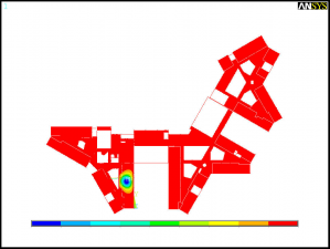
Fundamental frequency of 7.74 Hz
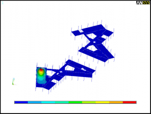
Fundamental frequency of 8.03 Hz


To determine these two types of response a modal analysis was performed using the finite element model. The modal analysis determined the natural frequencies and modal masses for each mode and the corresponding mode shapes. It was found that the fundamental natural frequency of the first and second floor was 7.74 and 8.03 Hz respectively. As the fundamental frequency of the two floors is below 10 Hz, the floors required to be assessed for both steady state response and transient response to walking activities.
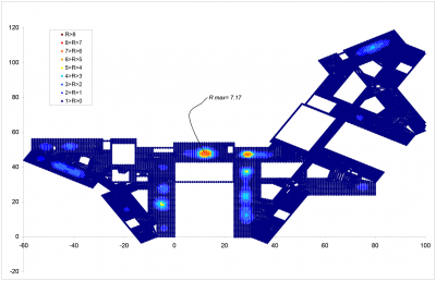

A modal superposition analysis was performed to determine the accelerations at the nodes representing the floors and the maximum response factor for the steady-state case was calculated to be 7.17. For the transient response case, considering the intermittent nature of the dynamic forces from walking, a maximum response factor of 5.10 was determined.
It has been be shown that the occupied floors achieve a minimum natural frequency of 4.0 Hz and a maximum response factor within the acceptable limit of R=8 for normal walking excitation. The steel frame and floor design therefore satisfied the acceptance criteria requested by the client.
References
- ↑ ISO 10137: Bases for design of structures – Serviceability of buildings against vibration, International Organisation for Standardization, 2007.
- ↑ BS 6472-1:2008, Guide to evaluation of human exposure to vibration in buildings. Vibration sources other than blasting, BSI.
- ↑ SCI P354: Design of floors for vibration: A new approach (Revised Edition), 2009