


Structural robustness
This article presents an overview of design guidance for hot-rolled steel framed buildings on the Eurocode strategies for structural robustness and designing for the avoidance of disproportionate collapse as required by the UK Building Regulations. Summarised design guidance in accordance with the Eurocodes is presented for the four building classes in the Eurocodes and the UK Building Regulations. Guidance on recommended good practice is presented where the Eurocodes do not give requirements or where they are not specific and are open to interpretation.

[top]Design codes and standards
The Eurocodes and the UK Building Regulations include requirements for providing 'robustness' and the avoidance of disproportionate collapse in hot-rolled steel framed buildings.
[top]Eurocodes

Within the Eurocodes, the majority of the robustness related clauses are given in BS EN 1991[1] and in particular Part 1-7[2]. However, reference to BS EN 1993[3] and BS EN 1990[4] is also necessary.
Robustness is defined in BS EN 1991-1-7[2] Actions on structures. General actions. Accidental actions, as follows:
"Robustness is the ability of a structure to withstand events like fire, explosions, impact or the consequences of human error, without being damaged to an extent disproportionate to the original cause."
From this definition it can be concluded that a structure designed and constructed to have robustness will not suffer from disproportionate collapse. Design for avoidance of disproportionate collapse is a requirement of Building Regulations in the UK.
In essence, the objective is to ensure that buildings do not suffer disproportionate collapse under accidental loading. Largely, this is assured in steel framed buildings by designing connections appropriately.
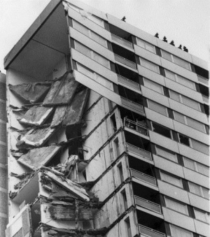
The terms disproportionate collapse and progressive collapse are often used interchangeably but it is possible to make a distinction. Progressive collapse is the spread of structural collapse from the initial failure of one or a few localised structural elements. If progressive collapse occurs it does not necessarily result in disproportionate collapse. However, the Ronan Point collapse illustrates a case where progressive collapse did result in disproportionate collapse. The Ronan Point collapse was the motivation for introducing disproportionate collapse regulations in the UK.
[top]Building Regulations
In the UK, there are four different sets of Building Regulations, one for each of the following jurisdictions:
- England
- Wales
- Scotland
- Northern Ireland.
Although the wording varies slightly, the 'Requirement' concerning disproportionate collapse is essentially the same in all four jurisdictions.
Requirement A3 from Part A of the Building Regulations as they apply in England and in Wales is given below.
"The building shall be constructed so that in the event of an accident the building will not suffer collapse to an extent disproportionate to the cause."
In each of the four jurisdictions listed above, official guidance documents are published to explain how compliance with the regulatory requirements may be achieved.
In England and in Wales, the guidance documents are termed Approved Documents and there is one for each part of the Regulations. Approved Document A[5] includes guidance on how the key robustness requirement A3 should be applied to different types and sizes of building.
In this article, where Approved Document A[5] is referenced, it is the English version.
In Scotland, guidance on satisfying the regulations is given in The Scottish Government Technical Handbooks [6].
In Northern Ireland, guidance on satisfying the regulations is given in The Building Regulations (Northern Ireland), Technical Booklet D [7]
(Note:On 31 December 2011 Wales became responsible for the majority of functions under the Building Act 1984 - including the making of Building Regulations. At that point in time, Wales adopted the same Approved Documents as were currently in use in England. Since that date, a number of changes have been made to various Approved Documents with respect to both England and Wales. Stakeholders should consult the Building Regulations web pages of the Ministry of Housing, Communities and Local Government and theWelsh Government for the most up to date versions of the Approved Documents as they apply to England or Wales respectively).
[top]Design strategies
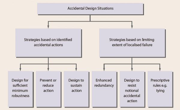

Two generic types of strategy for designing robust structures for accidental actions are provided in BS EN 1991-1-7[2]:
(a) Strategies based on identified accidental actions
(b) Strategies based on unidentified accidental actions.
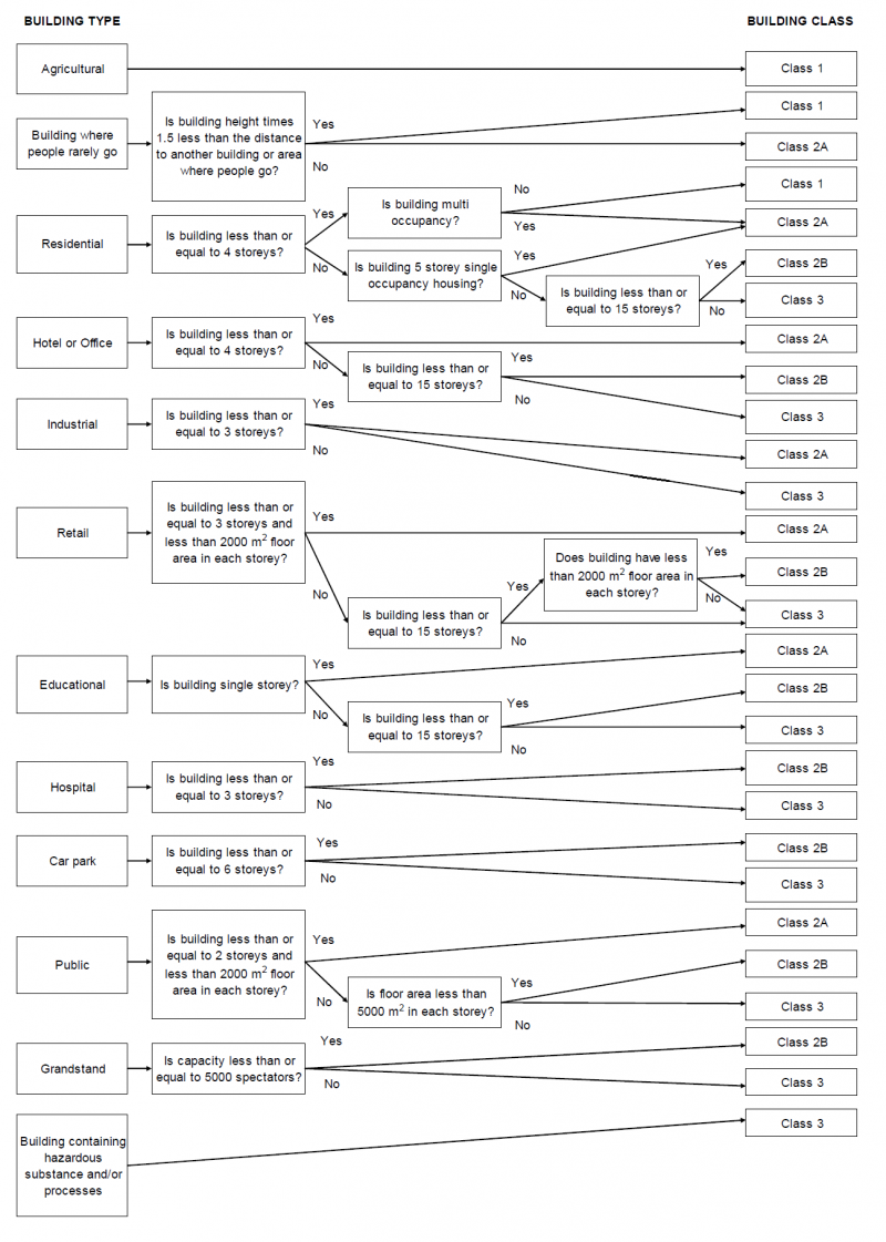
[top]Building classification
Approved Document A[5] sets out different required levels of robustness for different types and sizes of buildings. There are four classes of building:
- Class 1
- Class 2A
- Class 2B
- Class 3.
The building classification presented in Approved Document A[5] is the same as that presented in the SBSA Technical Handbooks[6] and there is only a small difference from that presented in BS EN 1991-1-7[2] .
[top]Robustness requirements
The basic robustness requirements for each of the different building classes are as follows.
[top]For Class 1 buildings
Provided that the building has been designed and constructed in accordance with the rules given in Approved Document A[5] for normal use, no additional measures are likely to be necessary.
[top]For Class 2A buildings
Effective horizontal ties should be provided for framed construction.
[top]For Class 2B buildings
There are three methods by which the robustness requirements may be satisfied for Class 2B buildings.
- Provide effective horizontal ties, together with effective vertical ties in all supporting columns.
- Check that upon the notional removal of a supporting column or a beam supporting one or more columns (one at a time in each storey of the building), the building remains stable and that the area of floor at any storey at risk of collapse does not exceed 15% of the floor area of that storey or 100 m², whichever is smaller, and does not extend further than the immediate adjacent storeys.
- Where the notional removal of such columns (or beams supporting one or more columns) would result in damage in excess of the above limit, then such elements should be designed as key elements.
[top]For Class 3 buildings
A systematic risk assessment of the building should be undertaken, taking into account all the normal hazards that can reasonably be foreseen, together with any abnormal hazards. Critical situations for design should be selected that reflect the conditions that can reasonably be foreseen as possible during the life of the building.
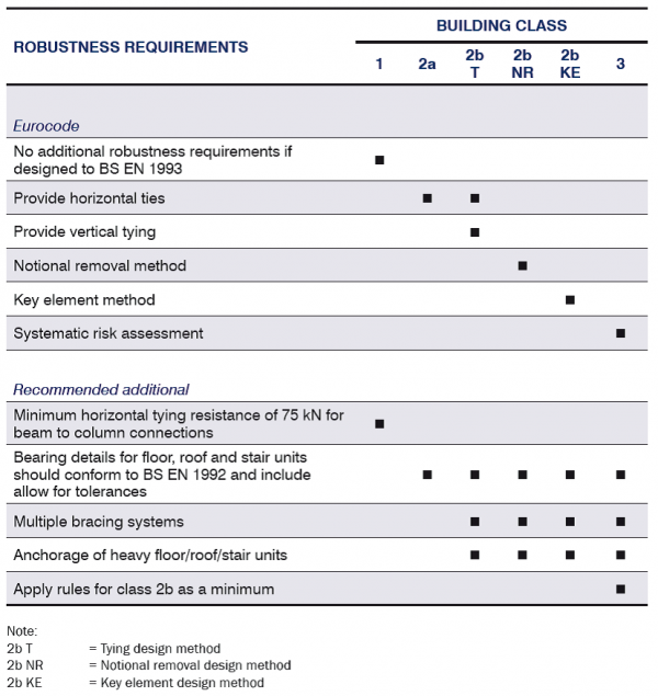
[top]Summary of robustness requirements
A summary of the robustness requirements for the different building classes is given. The requirements are divided into two categories, the requirements of the Eurocodes and those requirements that are recommended in addition to the Eurocode requirements. Detailed explanations of all the requirements are given in SCI P391.

[top]Consequences classes
Annex A of BS EN 1991-1-7[2] provides a method to categorise buildings in four consequences classes. The building categorisation considers the building type, occupancy and size.
The building classification is a simplification of a complex risk-based building classification system. The classes are only partly related to the building size, the other main factor is the building use, which takes account of socio-economic factors. Hence, hospitals and schools , for example, generally have a higher classification than other buildings of a similar size. The risk-based approach calculates a risk factor for each type of building based on the following variables:
- The number of people at risk
- The location of the structure and its height
- The perception in society of damage to the structure
- The type of load and likelihood that the load will occur at the same time as a large number of people being present within or near the structure
- The structural type and nature of the material.
For buildings intended for more than one type of use, the 'consequences class' should be that relating to the most onerous type. In determining the number of storeys, basement storeys may be excluded, provided that such basement storeys fulfil the requirements of 'Consequences Class 2b Upper Risk Group'.
[top]Consequence class 1
Low consequences of failure. Typical building type and occupancy:
- Single occupancy houses not exceeding 4 storeys.
- Agricultural buildings.
- Buildings into which people rarely go, provided no part of the building is closer to another building, or area where people do go, than a distance of 1.5 times the building height.
[top]Consequence class 2a
Lower risk group - Medium consequences of failure. Typical building type and occupancy:
- 5 storey single occupancy houses.
- Hotels not exceeding 4 storeys.
- Flats, apartments and other residential buildings not exceeding 4 storeys.
- Offices not exceeding 4 storeys.
- Industrial buildings not exceeding 3 storeys.
- Retail premises not exceeding 3 storeys of less than 1000 m² floor area in each storey.
- Single storey educational buildings.
- All buildings not exceeding two storeys to which the public are admitted and which contain floor areas not exceeding 2000 m² at each storey.
[top]Consequence class 2b
Upper risk group - Medium consequences of failure. Typical building type and occupancy:
- Hotels, flats, apartments and other residential buildings greater than 4 storeys but not exceeding 15 storeys.
- Educational buildings greater than single storey but not exceeding 15 storeys.
- Retail premises greater than 3 storeys but not exceeding 15 storeys.
- Hospitals not exceeding 3 storeys.
- Offices greater than 4 storeys but not exceeding 15 storeys.
- All buildings to which the public are admitted and which contain floor areas exceeding 2000 m² but not exceeding 5000 m² at each storey.
- Car parking not exceeding 6 storeys.
[top]Consequence class 3
High consequences of failure. Typical building type and occupancy:
- All buildings defined above as Class 2 Lower and Upper Consequences Class that exceed the limits on area and number of storeys.
- All buildings to which members of the public are admitted in significant numbers.
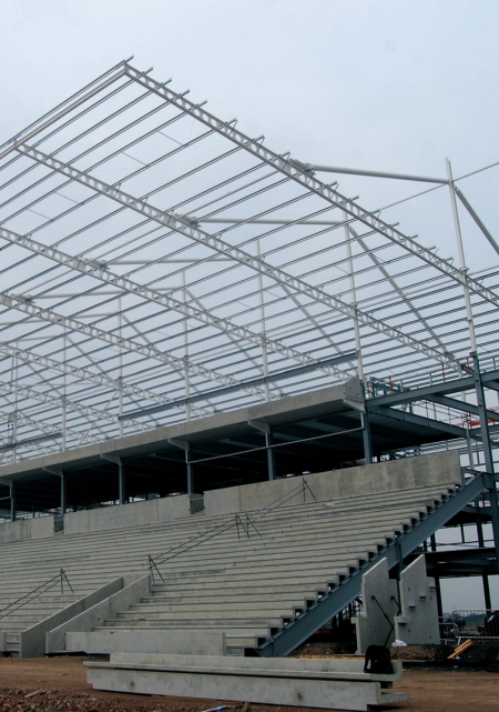
- Stadia accommodating more than 5000 spectators
- Buildings containing hazardous substances and / or processes

[top]Classification issues
In practice, many buildings will not fall simply into one of the classification descriptions. There are many reasons why this could be the case, for example mixed use, basements and varying number of storeys. Additional guidance on building classification issues is available in SCI P391.
[top]Horizontal tying
Horizontal tying can be beneficial to a structure in an accidental action situation by:
- Enabling catenary action to develop
- Holding columns in place.
[top]Catenary action

The principle of providing horizontal ties notionally allows for beam members to support loads by forming catenaries over damaged areas of structure. The provision of horizontal ties, designed to the Eurocode rules, has no complementary requirements relating to joint ductility or joint rotation capacity.
The robustness rules are not meant to fully describe systems of structural mechanics but are considered as rules intended to produce structures that perform adequately in accidental circumstances. Applying the rules contributes towards support over damaged areas of structure where the support provided by a column has been lost.
[top]Holding columns in place
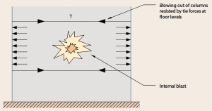

Accidental actions can cause horizontal forces to act on column sections. Ensuring that beam-to-column connections have tying resistance helps to hold the column in place and therefore that it can continue to support vertical loads.
The accidental action is often depicted as an internal blast but the principle applies to any accidental action that can cause horizontal forces. Holding columns in place also, importantly, helps to prevent floor units falling due to the spread of beams that could occur if columns were not held in position.
[top]Design forces
The requirements for horizontal ties (magnitude of tie capacity and location) are dependent on the building class and the design standard that is being followed, i.e. British Standards or Eurocodes.
[top]For Class 1 buildings
There is no specific requirement to provide horizontal ties for robustness in the Eurocodes.
[top]For Class 2a buildings
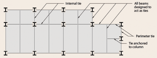

There is a specific requirement to provide horizontal ties for robustness in the Eurocodes. Each tie member, including its end connections, should be capable of sustaining a design tensile load of Ti for the accidental limit state in the case of internal ties, and Tp, in the case of perimeter ties. The magnitudes of Ti and Tp are calculated according to equations A.1 and A.2 from BS EN 1991‑1‑7[2].
Ti = 0.8(gk + ψ qk) s L or 75 kN, whichever is the greater
Tp = 0.4(gk + ψ qk) s L or 75 kN, whichever is the greater
where:
- gk is the permanent action
- qk is the variable action
- s is the spacing of the ties
- L is the span of the tie
- ψ is the relevant factor in the expression for combination of action effects for the accidental design situation, i.e. ψ1 as tabulated in the UK National Annex to BS EN 1990[4].
All beams should be designed to act as ties in a Class 2a building.
[top]For Class 2b buildings
The horizontal tying requirements are the same as those for Class 2a if the tying method for robustness is being used.
[top]For Class 3 buildings
The horizontal tying requirements are dependent on the results of the risk assessment. However, it is recommended that the Class 2b requirements are followed as a minimum.
[top]Vertical ties
Providing vertical ties for robustness is a requirement of the Eurocodes for Class 2b buildings if the tying method for robustness is being used.
[top]Benefits of providing vertical ties

Vertical tying resistance is beneficial to a structure in an accidental action situation by allowing loads to be redistributed through the structure via alternative load paths, away from locally damaged areas. Vertical ties also help to limit the risk of the upper floor being blown upwards in an explosion.
[top]Design rules
The requirements of vertical ties, as defined in BS EN 1991-1-7[2], A.6, are given below.
Vertical ties should be:
- Provided in columns, such that each column is tied continuously from the foundations to the roof level.
- Capable of resisting a tensile force equal to the largest design vertical permanent and variable load reaction applied to the column from any one storey. Such accidental design loading should not be assumed to act simultaneously with permanent and variable actions that might be acting on the structure.
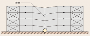
Vertical tying is provided by the tension resistance of column splices. The vertical tying resistance that is required for column splices is the largest total of the beam end reactions applied to the column at a single floor level. More details of tying forces may be found in SCI AD415.
- Common steel column splice details


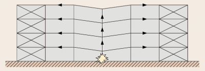
[top]Notional removal
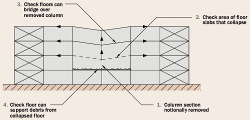

The notional removal method is presented in BS EN 1991-1-7[2] as an alternative to providing horizontal and vertical tying in a Class 2b building.
For the notional removal method, each supporting member should be notionally removed one at a time to ensure that the limit of admissible local damage is not exceeded and that the building remains stable.
In framed construction a supporting member is defined as a column section (a length between adjacent storeys) or a beam supporting one or more columns.
The notional removal method can be summarised into four basic steps:
- Column section notionally removed.
- Check the area of floor slabs that collapse.
- Check if floors above can bridge over the removed column.
- Check if the floor below can support debris from the collapsed floor.
[top]Key elements
The key element design approach may be applied where the requirements of the tying method or the notional removal method have not been satisfied.
[top]Benefits of key element design
The key element approach is fundamentally different from the tying approach and the notional removal approach, both of which are focused on limiting the spread of damage, or collapse, following an event that has caused a supporting element to be damaged. In contrast, the key element approach is focused on preventing the supporting element being damaged (to an extent that it can not provide the required support) following an accidental event and thus preventing excessive failure.
[top]Design rules
The requirements of key element design as defined in A.8 of BS EN 1991-1-7[2] are given below.
- Key elements should be capable of sustaining an accidental design action of Ad applied in horizontal and vertical directions (in one direction at a time) to the member and any attached components
- The recommended value of Ad for building structures is 34 kN/m²
- The accidental design action should be applied to the key element and any attached components having regard for the ultimate strength of attached components and their connections
- The accidental design loading should be applied in accordance with expression (6.11b) of BS EN 1990[4].
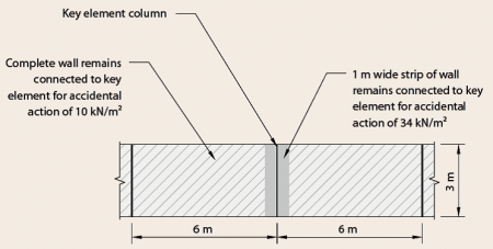
[top]Components attached to key elements
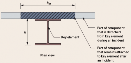

BS EN 1991-1-7[2] , A.8 clearly states that the accidental design action (Ad) should be applied to the key element and any attached components having regard for the ultimate strength of attached components and their connections. For the design of a key element, it is necessary to consider what components, or proportion of components, will remain attached to the element in the event of an incident. The application of engineering judgement will play a major part in this process.
The amount of component that remains attached to the key element will depend on the magnitude of the accidental load. The scenario that produces the highest load on the key element should be considered in design.

[top]Risk assessment
A systematic risk assessment is the major difference between the Eurocode robustness strategy of Class 3 buildings and that of Class 2b buildings. The purpose of a risk assessment is to determine whether there are any hazard scenarios that have an unacceptable level of risk and if so to identify steps to mitigate those risks.
[top]Risk analysis procedure
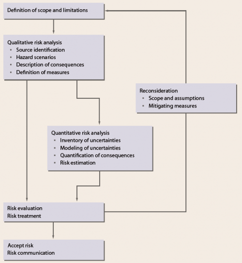

BS EN 1991-1-7[2] presents a flow diagram of the overall risk analysis procedure.
Both qualitative and quantitative approaches to risk analysis are acceptable. The risk assessment methodology that is used should be of sufficient detail to enable the hazard related risks to be ranked in order for the subsequent consideration of what risk reduction measures might be required. The rigour of assessment should be proportionate to the complexity of the problem and the magnitude of risks.
Qualitative and quantitative risk assessments can be broken down into several basic steps.
[top]Level of risk
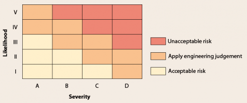
The level of risk associated with each hazard is usually expressed as a function of the severity and the likelihood of the hazard event.
For a qualitative assessment, a risk matrix is a convenient method of ranking the risks. Each hazard event is plotted on the risk matrix according to the appropriate severity and likelihood category. The acceptability of risks should be evaluated in order, starting with the highest risk.

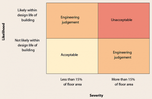
Where the likelihood is categorised by events that are more or less likely to occur within the design life of the building, and the severity of damage is assessed as being more or less than the collapse of 15% of a floor (the notional limit given in Approved Document A[5] and BS EN 1991-1-7[2]), it is often possible to simplify the considerations into a simple 2 by 2 matrix as shown.

[top]Risk mitigation
Risks can be mitigated in one of two ways:
- By eliminating the hazard event
- By reducing the probability of the hazard event and/or the severity of the consequences.
Totally eliminating the hazard event is not possible or practical in many situations but significantly reducing the probability or the consequences is often achievable at very little additional cost.
[top]References
- ↑ BS EN 1991 Eurocode 1. Actions on structures. General actions. Various parts, BSI
- ↑ 2.00 2.01 2.02 2.03 2.04 2.05 2.06 2.07 2.08 2.09 2.10 2.11 BS EN 1991-1-7:2006+A1:2014. Eurocode 1: Actions on structures. General actions. Accidental actions. BSI
- ↑ BS EN 1993 Eurocode 3: Design of steel structures. Various parts, BSI
- ↑ 4.0 4.1 4.2 BS EN 1990:2002+A1:2005. Eurocode: Basis of structural design. BSI
- ↑ 5.0 5.1 5.2 5.3 5.4 5.5 Approved Document A (Structure) 2004 Edition incorporating 2004, 2010, and 2013 amendments. Ministry of Housing, Communities & Local Government
- ↑ 6.0 6.1 Building standards technical handbook: 2019 – Non-domestic, Section 1 – Structure, The Scottish Government
- ↑ Technical Booklet D, Structure, Building Regulations (Northern Ireland) 2012, Department of Finance and Personnel of the Northern Ireland Government, 2012
[top]Further reading
- Practical Guide to Structural Robustness and Disproportionate Collapse in Buildings. The Institution of Structural Engineers, 2010.
- Harding, G and Carpenter, J. Disproportionate Collapse of 'Class 3' Buildings: The Use of Risk Assessment. The Structural Engineer, Vol. 87, Issue 15, 2009.
[top]Resources
- SCI P391 Structural Robustness of Steel Framed Buildings, 2011
- SCI P358 Joints in Steel Construction - Simple Joints to Eurocode 3, 2014
- SCI P398 Joints in Steel Construction - Moment resisting joints to Eurocode 3, 2013
- SCI AD415, Vertical tying of columns and column splices, 2018