


Skew bridges
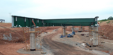
It is often not possible to arrange that a bridge spans square to the feature that it crosses, particularly where it is important to maintain a relatively straight alignment of a roadway above or below the bridge. Thus a ‘skew’ bridge is required. This increases the spans but more significantly usually results in the end and intermediate supports being at an angle to the longitudinal axis of the bridge, rather than square to it. Skew support arrangements give rise to torsional effects that must be taken into account in design.
This article gives an overview of the design consequences for skew alignment of bridges.

[top]Angle of skew
The term ‘angle of skew’ or ‘skew angle is generally applied to the difference between the alignment of an intermediate or end support and a line square to the longitudinal axis of the bridge above. Thus, on a straight bridge, the skew angle at all supports would normally be the same and the term skew angle can be applied to the bridge as a whole. On a curved bridge, the skew angle is different at each support.
[top]Girder layout
[top]Main girders


In multiple-span continuous bridges, the main girders, whether of multi-girder or ladder deck form, are arranged parallel to the longitudinal axis of the bridge, even for bridges with a high skew angle.
In single span bridges, the main girders are also usually parallel to the bridge axis but if the skew is very large (more than about 45°) or the bridge is very wide (much wider than its span), the multiple main girders might be placed square to the abutments.
In some cases, although the bridge may be skew to the feature that it crosses, supports may be provided square to the bridge axis, rather than skew. This increases the spans further and may require greater space for the support foundations.
In a ‘right’ deck with transverse members square to the main girders, the separation between bending and torsion effects is relatively clear and with reasonable proportioning, a model for analysis will perform well (said to be well conditioned). As skew is added, there is much more interaction – bridge decks will always tend to span square. Thus skew decks are less efficient at load carrying and skew transverse bracing will be less efficient than bracing at right angles to the main members. For a beam and slab, the strength tries to follow the direction of the girders. At high skews alternative arrangements should be considered as shown right.
[top]Cross girders and transverse bracing
[top]Multi-girder bridges
For skew angles up to about 25°, the bracing or crosshead girders at abutments and intermediate supports usually follow the line of the support bearings, as shown below. The consequence of this is that the planes of bracing are subject to some twist (because adjacent main girders deflect and rotate (in the planes of their webs) by different amounts and that the bracing offers some restraint to the bending of the main girders. However, such effects are relatively small.
Within the spans, transverse bracing is usually square to the main girders. Making such bracing skew offers little benefit and adds complexity to fabrication.


For skew angles over about 25°, the interaction between bracing and main girders becomes increasing significant and the main girders are twisted about their longitudinal axes by the displacement of the bracing. To minimize the interaction at intermediate supports, the bracing is usually made square to the main girders, as shown below. Whilst this does minimize interaction, it does not avoid twisting the main girders about their longitudinal axes (this can readily be appreciated by considering the bracing that connects to one girder at a support bearing and to the adjacent girder in the span (where vertical displacements occur).
At the abutments, all the girders are supported along the line of the skew and the bracing is provided in that direction. The interaction between main girders and bracing will be significant and must be considered in design; the effects could even result in uplift at the acute angle support.
Intermediate bracing is still provided square to the main girders.


[top]Ladder deck bridges
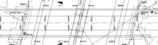
In ladder deck bridges, the cross girders are almost always square to the main girders, which means that arrangements at supports must be modified to match the skew angle.
At an end support, the spacing longitudinally is maintained and an abutment trimmer is introduced, as shown below. Connection of a cross girder at the support bearing should be avoided, to minimize conflict and interaction.
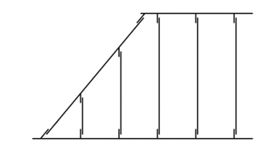
Layout of cross girders at skewed end support
Cross girders at skewed end support


At intermediate supports, the longitudinal spacing of cross girders is adjusted, so that one cross girder connects to each bearing stiffener, as shown below.
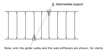
Layout of cross girders at skewed intermediate support
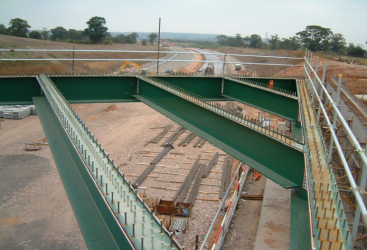
Intermediate support of ladder deck bridge with high skew


[top]Railway bridges


In half through railway bridges, for small skew angles, the cross girders are usually parallel to the abutment and for large skew angles, cross girders are square to the main girders, supported on trimmer girders at the abutments. For some intermediate skew angles, the cross girders in the centre part of the span are arranged orthogonal to the main girders and at the end of the span the girders nearest the abutment may be fanned to the trimmer beams (termed fanned cross girders).
[top]Design

Although torsional effects on individual girders can be minimized by choice of layout, as discussed above, the model used for global analysis must be capable of identifying all the effects that are consequent on the skew layout and the skew connections between members.
One particular issue that arises with large skew angles is that reactions at the abutments will be redistributed such that uplift can occur under certain load cases at certain bearings. Usually this occurs in acute corners, but for torsionally stiff multi-girder decks with high skew, it can also occur just in from the obtuse corner as well.
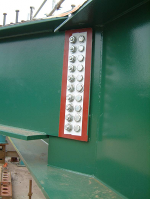
In detailing skew connections, the geometry needs to be considered carefully and any construction issues, such as difficulty of welding in acute corners or of inserting and tightening bolts, should be anticipated and suitable solutions found.
As a result of the skew geometry, main girders will twist about their longitudinal axes during construction and it can be difficult to predict the exact rotation at the end of a sequential construction sequence for a composite bridge. The girder webs may not be truly vertical at the end of construction. Advice on this aspect is given in Guidance Note 7.03.
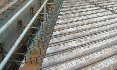
General guidance on detailing, including the orientation of the slab reinforcement and the need to avoid conflict between stud connectors and reinforcing bars, is given in Guidance Note 1.02 and in SCI P356.

[top]Resources
- Iles, D.C. (2010) Composite highway bridge design. (P356 including corrigendum, 2014). SCI
- Hendy, C.R.; Iles, D.C. (2015) Steel Bridge Group: Guidance Notes on best practice in steel bridge construction (6th Issue). (P185). SCI
[top]See also
- Multi-girder composite bridges
- Ladder deck composite bridges
- Half-through bridges
- Modelling and analysis of beam bridges
- Bracing systems
- Stiffeners
- Connections in bridges
- Bridge articulation and bearing specification
- Design for steel bridge construction
- Fabrication
- Welding
- Preloaded bolting