


Difference between revisions of "Simple connections"
| (11 intermediate revisions by the same user not shown) | |||
| Line 8: | Line 8: | ||
==Types of simple connections == | ==Types of simple connections == | ||
| − | [[Simple_connections|Simple connections]] are nominally pinned connections that are assumed to transmit end shear only and to have negligible resistance to rotation. Therefore do not transfer significant moments at the ultimate limit state. This definition underlies the design of [[Multi-storey_office_buildings|multi-storey]] [[Braced_frames|braced frames]] in the UK designed as 'simple construction', in which the beams are designed as simply-supported and the columns are designed for axial load and the small moments induced by the end reactions from the beams. Stability is provided to the frame by bracing or by | + | [[Simple_connections|Simple connections]] are nominally pinned connections that are assumed to transmit end shear only and to have negligible resistance to rotation. Therefore do not transfer significant moments at the ultimate limit state. This definition underlies the design of [[Multi-storey_office_buildings|multi-storey]] [[Braced_frames|braced frames]] in the UK designed as 'simple construction', in which the beams are designed as simply-supported and the columns are designed for axial load and the small moments induced by the end reactions from the beams. Stability is provided to the frame by bracing or by a steel or concrete core. |
{{#image_template:image=File:K1_Fig41.jpg|align=right|wrap=true|width=400|caption=Simple connections}} | {{#image_template:image=File:K1_Fig41.jpg|align=right|wrap=true|width=400|caption=Simple connections}} | ||
Two principle forms of simple connection (as shown on the right) are used in the UK, these being: | Two principle forms of simple connection (as shown on the right) are used in the UK, these being: | ||
| Line 69: | Line 69: | ||
===Selection of connection types=== | ===Selection of connection types=== | ||
| − | The selection of beam end connections | + | The selection of beam end connections is straightforward. The relative merits of the three connection types (partial depth [[#Flexible end plate connections|end plates]], full depth [[#Flexible end plate connections|end plates]] and [[#Fin plates|fin plates]]) are summarised in the table below. Connection selection and verification is generally the responsibility of the steelwork contractor who will choose the connection type to suit the fabrication workload, economy and temporary stability during erection. If semi-continuous design is utilised, both the beam and its connections must be selected and verified by the frame designer. Further information on semi-continuous frames is provided in [[#Resources|SCI P183]] and [[#Resources|SCI P263]]. |
{| class="wikitable" width=700 | {| class="wikitable" width=700 | ||
|+'''Relative merits of beam end connection types''' | |+'''Relative merits of beam end connection types''' | ||
| Line 167: | Line 167: | ||
The design procedures given below are suitable for either hand calculation or for the preparation of computer software. | The design procedures given below are suitable for either hand calculation or for the preparation of computer software. | ||
| − | Designing connections by hand can be a laborious process and so a full set of resistance tables | + | Designing connections by hand can be a laborious process and so a full set of resistance tables is included in the '[[The Green Books|Green Book]]' [[#Resources|(SCI P358)]]. |
Verifying the strength of a nominally pinned joint involves three stages: | Verifying the strength of a nominally pinned joint involves three stages: | ||
| Line 210: | Line 210: | ||
|13 Tying resistance||colspan=3|Welds | |13 Tying resistance||colspan=3|Welds | ||
|- | |- | ||
| − | |14 Tying resistance||colspan=3|Supporting column web ([[Steel construction products#Standard open sections| | + | |14 Tying resistance||colspan=3|Supporting column web ([[Steel construction products#Standard open sections|UC or UB]]) |
|- | |- | ||
|15 Tying resistance||colspan=3|Supporting column wall ([[Steel construction products#Structural hollow sections|RHS or SHS]]) | |15 Tying resistance||colspan=3|Supporting column wall ([[Steel construction products#Structural hollow sections|RHS or SHS]]) | ||
| Line 229: | Line 229: | ||
Typical flexible end plate connections are shown in the figure right. The end plate, which may be partial depth or full depth, is welded to the supported beam in the workshop. The beam is then bolted to the supporting beam or column on site. | Typical flexible end plate connections are shown in the figure right. The end plate, which may be partial depth or full depth, is welded to the supported beam in the workshop. The beam is then bolted to the supporting beam or column on site. | ||
| − | This type of connection is relatively inexpensive | + | This type of connection has a high shear resistance and is relatively inexpensive. It is often used to connect primary beams to columns. Packs may be used to compensate for [[Accuracy_of_steel_fabrication#Fabrication_tolerances|fabrication tolerances]] and erection tolerances. |
End plates are probably the most popular of the simple beam connections currently in use in the UK. They can be used with skewed beams and can tolerate moderate offsets in beam to column joints. | End plates are probably the most popular of the simple beam connections currently in use in the UK. They can be used with skewed beams and can tolerate moderate offsets in beam to column joints. | ||
| Line 288: | Line 288: | ||
==Fin plates== | ==Fin plates== | ||
{{#image_template:image=File:C18-04.png|caption=Fin plate beam to column and beam to beam connections|align=right|wrap=true|width=380}} | {{#image_template:image=File:C18-04.png|caption=Fin plate beam to column and beam to beam connections|align=right|wrap=true|width=380}} | ||
| − | Fin plate connections are economical to fabricate and simple to erect. These connections are popular, as they can be the quickest connections to erect and overcome the problem of shared bolts in two-sided connections. | + | Fin plate connections are economical to fabricate and simple to erect. These connections are popular, as they can be the quickest connections to erect and overcome the problem of shared bolts in two-sided connections. Fin plates have a high tying resistance. They are often used to connect secondary beams to primary beams, or to columns. |
A fin plate connection consists of a length of plate welded in the workshop to the supporting member, to which the supported beam web is bolted on site, as shown in the figure below. There is a small clearance between the end of the supported beam and the supporting column. | A fin plate connection consists of a length of plate welded in the workshop to the supporting member, to which the supported beam web is bolted on site, as shown in the figure below. There is a small clearance between the end of the supported beam and the supporting column. | ||
| Line 298: | Line 298: | ||
In the design of a fin plate connection it is important to identify the appropriate line of action for the shear. There are two possibilities: either the shear acts at the face of the column or it acts along the centre of the bolt group connecting the fin plate to the beam web. For this reason both critical sections should be checked for a minimum moment taken as the product of the vertical shear and the distance between the face of the column (or beam web) and the centre of the bolt group. Both critical sections are then checked for the resulting moment combined with the vertical shear. Due to the uncertainty of the moment applied to the fin plate, the fin plate welds are sized to be full strength. | In the design of a fin plate connection it is important to identify the appropriate line of action for the shear. There are two possibilities: either the shear acts at the face of the column or it acts along the centre of the bolt group connecting the fin plate to the beam web. For this reason both critical sections should be checked for a minimum moment taken as the product of the vertical shear and the distance between the face of the column (or beam web) and the centre of the bolt group. Both critical sections are then checked for the resulting moment combined with the vertical shear. Due to the uncertainty of the moment applied to the fin plate, the fin plate welds are sized to be full strength. | ||
| − | Fin plate connections derive their in-plane rotational capacity | + | Fin plate connections primarily derive their in-plane rotational capacity from the distortion of the bolt holes in bearing and from the out-of-plane bending of the fin plate. Note that fin plates with long projections have a tendency to twist and may fail by lateral torsional buckling if the beam is unrestrained. An additional check to consider this behaviour is included in the design procedures for fin plate connections. |
The '[[The Green Books|Green Book]]' [[#Resources|(SCI P358)]] covers detailing requirements, design checks and procedures applicable to fin plate design. Worked examples and design resistance tables are also given in this publication. | The '[[The Green Books|Green Book]]' [[#Resources|(SCI P358)]] covers detailing requirements, design checks and procedures applicable to fin plate design. Worked examples and design resistance tables are also given in this publication. | ||
| Line 348: | Line 348: | ||
When no net tension is present, a standard connection can be used, however BS EN 1993-1-8<ref name="BSEN1993-1-8"></ref> imposes the requirement for the splice plates and bolts to transmit at least 25% of the maximum compressive force in the column. | When no net tension is present, a standard connection can be used, however BS EN 1993-1-8<ref name="BSEN1993-1-8"></ref> imposes the requirement for the splice plates and bolts to transmit at least 25% of the maximum compressive force in the column. | ||
| − | For bearing type splices, the tying resistance is likely to be the critical check.<br clear=left> | + | For bearing type splices, the tying resistance, required in Class 2b buildings, is likely to be the critical check.<br clear=left> |
{{#image_template:image=File:C18-07.png|width=550|caption=Bearing column splices for rolled I sections}} | {{#image_template:image=File:C18-07.png|width=550|caption=Bearing column splices for rolled I sections}} | ||
Splices categorised as '''non-bearing type''' (see figure below) transfer loads via the bolts and splice plates. Any direct bearing between the members is ignored, the connection sometimes being detailed with a physical gap between the two shafts. The design of a non-bearing splice is more involved, as all forces and moments must be transmitted through the bolts and splice plates. For non-bearing type splices, the minimum requirements in BS EN 1993-1-8<ref name="BSEN1993-1-8"></ref> are very onerous, being based on member capacity rather than applied force. | Splices categorised as '''non-bearing type''' (see figure below) transfer loads via the bolts and splice plates. Any direct bearing between the members is ignored, the connection sometimes being detailed with a physical gap between the two shafts. The design of a non-bearing splice is more involved, as all forces and moments must be transmitted through the bolts and splice plates. For non-bearing type splices, the minimum requirements in BS EN 1993-1-8<ref name="BSEN1993-1-8"></ref> are very onerous, being based on member capacity rather than applied force. | ||
| − | As splices are generally provided just above floor levels the moment due to strut action is considered insignificant. The moments induced in splices placed at other positions, however, should be taken into account. | + | As splices are generally provided just above floor levels the moment due to strut action is considered insignificant. The moments induced in splices placed at other positions, however, should be taken into account. [[Media:AD-471.pdf|AD 471]] provides comprehensive advice on the calculation of the bending moments to be included in the splice design. |
{{#image_template:image=File:C18-08.png|width=700|caption=Non bearing column splices for rolled I sections}} | {{#image_template:image=File:C18-08.png|width=700|caption=Non bearing column splices for rolled I sections}} | ||
Column splices should hold the connected members in line, and wherever practical, the members should be arranged so that the centroidal axis of the splice material coincides with the centroidal axis of the column sections above and below the splice. If the column sections are offset (for example to maintain a constant external line) the moment due to the eccentricity should be accounted for in the joint design. | Column splices should hold the connected members in line, and wherever practical, the members should be arranged so that the centroidal axis of the splice material coincides with the centroidal axis of the column sections above and below the splice. If the column sections are offset (for example to maintain a constant external line) the moment due to the eccentricity should be accounted for in the joint design. | ||
| Line 435: | Line 435: | ||
*[[Media:SCI_P391.pdf|SCI P391 Structural Robustness of Steel Framed Buildings, 2011]] | *[[Media:SCI_P391.pdf|SCI P391 Structural Robustness of Steel Framed Buildings, 2011]] | ||
*[[Media:SCI_P398.pdf|SCI P398 Joints in steel construction: Moment-resisting joints to Eurocode 3, 2013]] | *[[Media:SCI_P398.pdf|SCI P398 Joints in steel construction: Moment-resisting joints to Eurocode 3, 2013]] | ||
| − | *[https:// | + | *[https://bcsa.org.uk/product/nsss-7th-edition-pdf/ National Structural Steelwork Specification (7th Edition), 2020, (Publication No. 62/20), BCSA] |
| − | *[https:// | + | *[https://bcsa.org.uk/product/commentary-3rd-edition-nsss-7th-edition-book/ Commentary (3rd edition) on the National Structural Steelwork Specification for Building Construction (7th edition), 2022, (Publication No. 66/22), BCSA] |
*[[Media:SCI_P167.pdf|Architectural Teaching Resource. Studio Guide. SCI 2003]] | *[[Media:SCI_P167.pdf|Architectural Teaching Resource. Studio Guide. SCI 2003]] | ||
| + | *[[Media:SCI_P183.pdf|SCI P183 Design of Semi-Continuous Braced Frames, 1997]] | ||
| + | *[[Media:SCI_P263.pdf|SCI P263 Wind-moment Design of Low Rise Frames, 1999]] | ||
<br> | <br> | ||
Connection design tools:<br> | Connection design tools:<br> | ||
Latest revision as of 13:46, 3 April 2023
This article considers nominally pinned joints (simple connections) which are used in multi-storey braced frames in the UK. This form of braced construction, with nominally pinned joints, is termed 'simple construction'.
The article lists the types of simple connections that are most commonly used in the UK. It presents the procedures for their design to Eurocode 3 and discusses the relative merits of beam end connection types. The benefits of standardisation of connections are discussed for beam-to-beam and beam-to-column connections using fin plate and flexible end plate connections.
Column splices, column bases and bracing connections are also discussed together with a brief mention given to special connections.


[top]Types of simple connections
Simple connections are nominally pinned connections that are assumed to transmit end shear only and to have negligible resistance to rotation. Therefore do not transfer significant moments at the ultimate limit state. This definition underlies the design of multi-storey braced frames in the UK designed as 'simple construction', in which the beams are designed as simply-supported and the columns are designed for axial load and the small moments induced by the end reactions from the beams. Stability is provided to the frame by bracing or by a steel or concrete core.
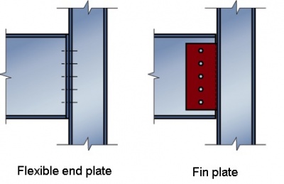

Two principle forms of simple connection (as shown on the right) are used in the UK, these being:
Commonly encountered simple connections include:
- Beam-to-beam and beam-to-column connections using:
- Partial depth end plates
- Full depth end plates
- Fin plates
- Column splices (bolted cover plates or end plates)
- Column bases
- Bracing connections (Gusset plates).
Simple connections can also be needed for skewed joints, beams eccentric to columns and connection to column webs. These are classed as special connections and are treated separately.
[top]Design procedures
The design of simple connections is based on BS EN 1993-1-8[1] and its accompanying National Annex[2]. The capacities of the connection components are based on the rules given in clause 3.6. The spacing of the fasteners comply with clause 3.5 and follow the recommendations presented in the 'Green Book' (SCI P358).
ECCS publication No. 126[3] also provides useful guidance on the design of simple connections to Eurocode 3.
[top]Joint considerations
[top]Joint classification
According to BS EN 1993-1-8[1], nominally pinned joints:
- Should be capable of transmitting the internal forces, without developing significant moments which might adversely affect the members or the structure as a whole and
- Be capable of accepting the resulting rotations under the design loads
In addition, the joint must:
- provide the directional restraint to members which has been assumed in the member design
- have sufficient robustness to satisfy the structural integrity requirements (tying resistance).
BS EN 1993-1-8[1] requires that all connections must be classified; by stiffness, which is appropriate for elastic global analysis, or by strength, which is appropriate for rigid plastic global analysis, or by both stiffness and strength, which is appropriate for elastic-plastic global analysis.
Classification by stiffness:
The initial rotational stiffness of the connection, calculated in accordance with BS EN 1993-1-8[1] , 6.3.1 is compared with the classification boundaries given in BS EN 1993-1-8[1], 5.2.2.
Alternatively, joints may be classified based on experimental evidence, experience of previous satisfactory performance in similar cases or by calculations based on test evidence.
Classification by strength:
The following two requirements must be satisfied in order to classify a connection as nominally pinned, based on its strength:
- The design moment resistance of the connection does not exceed 25% of the design moment resistance required for a full-strength joint
- The joint should be capable of accepting the rotations resulting from the design loads.
The UK National Annex to BS EN 1993-1-8[2] states that connections designed in accordance with the 'Green Book' (SCI P358) may be classified as nominally pinned joints.
All the standard connections given in the 'Green Book' (SCI P358) may be classified as nominally pinned based on the strength requirements together with extensive experience of details used in practice. Care should be taken before amending the standard details as the resulting connection may fall outside the provisions of the UK National Annex[2]. In particular:
- The rotation capacity of the standard fin plate details have been demonstrated by test; modified details may not be ductile
- The thickness of the full depth end plates have been limited to ensure the moment resistance is less than 25% of a full strength joint, and can thus be classified as nominally pinned.
[top]Structural integrity
The UK Building Regulations require that all buildings should be designed to avoid disproportionate collapse. Commonly, this is achieved by designing the joints in a steel frame (the beam-to-column connections and the column splices) for tying forces. Guidance on the design values of tying forces is given in BS EN 1991-1-7[4] Annex A, and its UK National Annex[5]. The requirements relate to the building Class, with a design value of horizontal tying force generally not less than 75 kN, and usually significantly higher. Full depth end plate details have been developed to provide an increased tying resistance compared to partial depth end plate details. Further details on structural robustness are presented in SCI P391 .
[top]Selection of connection types
The selection of beam end connections is straightforward. The relative merits of the three connection types (partial depth end plates, full depth end plates and fin plates) are summarised in the table below. Connection selection and verification is generally the responsibility of the steelwork contractor who will choose the connection type to suit the fabrication workload, economy and temporary stability during erection. If semi-continuous design is utilised, both the beam and its connections must be selected and verified by the frame designer. Further information on semi-continuous frames is provided in SCI P183 and SCI P263.
| Partial depth end plate | Full depth end plate | Fin plate | |
|---|---|---|---|
| Design | |||
| Shear resistance - percentage of beam resistance | Up to 75% | 100% | Up to 50% Up to 75% with two vertical lines of bolts |
| Tying resistance | Fair | Good | Good |
| Special considerations | |||
| Skewed Joints | Fair | Fair | Good |
| Beams eccentric to columns | Fair | Fair | Good |
| Connection to column webs | Good | Good | Fair To facilitate erection, flange stripping may be required. Stiffening may be required for long fin plates |
| Fabrication and treatment | |||
| Fabrication | Good | Good | Good Stiffening may be required for long fin plates |
| Surface treatment | Good | Good | Good |
| Erection | |||
| Ease of erection | Fair Care needed for two-sided connections |
Fair Care needed for two-sided connections |
Good |
| Site adjustment | Fair | Fair | Fair |
| Temporary stability | Fair | Good | Fair |
[top]Composite floors
It is recognised that interaction with a composite floor will affect the behaviour of a simple connection. Common practice is to design such connections without utilising the benefits of the continuity of reinforcement through the concrete slab. However, SCI P213 enables reinforcement continuity to be allowed for in providing relatively simple full depth end plate connections with substantial moment resistance. In a braced frame, this resistance may be used to reduce the mid-span moment and deflection, facilitating the selection of a smaller beam.
[top]Costs
Simple connections are invariably cheaper to fabricate than moment-resisting connections, because they involve much less fabrication effort, particularly in welding.
Giving specific guidance on costs is difficult, as a Steelwork Contractor's workmanship rates can vary considerably and are dependant upon the level of investment in plant and machinery. However, the main objective is to minimise work content. The material cost for fittings and bolts is small compared with workmanship costs which are dominated by welding content. In a typical fabrication workshop the cost of fabrication of connections may be 30% to 50% of the total fabrication cost.
[top]Sustainability
Standardised connections are efficient in their production. Steelwork Contractors equip their workshops with specialist machinery that increases the speed of fabrication, allowing them to produce fittings and prepare the members much more quickly than they would if the connection configuration were different each time.
The standardised details mean the steelwork is straightforward to erect, which provides a safer working environment for the steel erectors.
Due to the nature of most bolted joints, the connections are demountable at the end of the service life of the structure. The steelwork can be dismantled, reused or recycled, therefore reducing the environmental impact of the construction.
[top]Standardised connections
[top]The benefits of standardisation
In a typical braced multi-storey frame, the connections may account for less than 5% of the frame weight, and 30% or more of the total cost. Efficient connections will therefore have the lowest detailing, fabrication and erection labour content.
| Component | Preferred Option | Notes |
|---|---|---|
| Fittings | Material of grade S275 | Recommended sizes of end plates and fin plates – see table below |
| Bolts | M20 8.8 Bolts, fully threaded | Some heavily loaded connections may need larger diameter bolts Foundation bolts may be M20, M24, M30, 8.8 or 4.6 |
| Holes | Generally 22 mm diameter, punched or drilled | 26 mm diameter for M24 bolts 6 mm oversize for foundation bolts |
| Welds | Fillet welds generally 6 mm or 8 mm leg length | Larger welds may be needed for some column bases |
| Fittings | Location | ||
|---|---|---|---|
| Size (mm) | Thickness (mm) | End plate | Fin plate |
| 100 | 10 | • | |
| 120 | 10 | • | |
| 150 | 10 | • | • |
| 160 | 10 | • | |
| 180 | 10 | • | • |
| 200 | 12 | • | |
[top]Beam-to-beam and beam-to-column connections
The design procedures given below are suitable for either hand calculation or for the preparation of computer software.
Designing connections by hand can be a laborious process and so a full set of resistance tables is included in the 'Green Book' (SCI P358).
Verifying the strength of a nominally pinned joint involves three stages:
- Ensuring that the joint is detailed such that it develops only nominal moments which do not adversely affect the members or the joint itself. The joint should be detailed so that it behaves in a ductile manner.
- Identifying the load path through the joint i.e. from the beam to the supporting member.
- Checking the resistance of each component.
For normal design there are ten design procedure checks for all the parts of a beam to beam or beam to column joint for vertical shear.
A further six checks are necessary to verify the tying resistance of the joint. Beam to column connections must be able to resist lateral tying forces unless these forces are resisted by other means within the structure, such as the floor slabs.
The table below summarises the design procedure checks required for partial depth end plates, full depth end plates and fin plates. The design procedures are described fully in the 'Green Book' (SCI P358).
| Design procedure checks | Partial-depth end plate | Full-depth end plate | Fin plate |
|---|---|---|---|
| 1 Recommended detailing practice | ✔ | ✔ | ✔ |
| 2 Supported beam | Welds | Welds | Bolt Group |
| 3 Supported beam | N/A | N/A | Fin plate |
| 4 Supported beam | Web in shear | ||
| 5 Supported beam | Resistance at a notch | N/A | Resistance at a notch |
| 6 Supported beam | Local stability of notched beam | N/A | Local stability of notched beam |
| 7 Unrestrained supported beam | Overall stability of notched beam | N/A | Overall stability of notched beam |
| 8 Connection | Bolt group | Bolt group | Welds |
| 9 Connection | End plate in shear | N/A | N/A |
| 10 Supporting beam/column | Shear and bearing | ||
| 11 Tying resistance | Plate and bolts | ||
| 12 Tying resistance | Supported beam web | ||
| 13 Tying resistance | Welds | ||
| 14 Tying resistance | Supporting column web (UC or UB) | ||
| 15 Tying resistance | Supporting column wall (RHS or SHS) | ||
| 16 Tying resistance | N/A | N/A | Supporting column wall (CHS) |
Notes: Checks on the bending, shear, local and lateral buckling resistance of a notched beam section are included in this table as it is usually at the detailing stage that the requirement for notches is established, following which, a check must be made on the reduced section
Beam-to-beam connections
Beam-to-column connections
[top]Flexible end plate connections


Typical flexible end plate connections are shown in the figure right. The end plate, which may be partial depth or full depth, is welded to the supported beam in the workshop. The beam is then bolted to the supporting beam or column on site.
This type of connection has a high shear resistance and is relatively inexpensive. It is often used to connect primary beams to columns. Packs may be used to compensate for fabrication tolerances and erection tolerances.
End plates are probably the most popular of the simple beam connections currently in use in the UK. They can be used with skewed beams and can tolerate moderate offsets in beam to column joints.
Flowdrill, Hollo-Bolts, Blind bolts or other special assemblies are used for connections to hollow section columns.
Detailing requirements and design checks for partial depth and full depth end plates connections, which are applicable to beam-to-beam connections as well as beam-to-column connections, are comprehensively covered in the 'Green Book' (SCI P358). These include procedures, worked examples, detailing and design resistance tables.
An End plate designer tool is also available.
Standard flexible end plate details (full depth and partial depth end plates) are shown in the figure below, together with recommended dimensions and fittings.


| Supported beam | Recommended end plate size bp × tp |
Bolt gauge p3 | ||||||||||
|---|---|---|---|---|---|---|---|---|---|---|---|---|
| Up to 533 UB | 150 × 10 | 90 | ||||||||||
| 533 UB and above | 200 × 12 | 140 | ||||||||||
| ||||||||||||
| Supported beam | Recommended end plate size bp × tp |
Bolt gauge p3 | ||||||||
|---|---|---|---|---|---|---|---|---|---|---|
| Up to 533 UB | 180 × 10 | 90 | ||||||||
| 533 UB and above | 200 × 12 | 110 | ||||||||
| ||||||||||
[top]Fin plates


Fin plate connections are economical to fabricate and simple to erect. These connections are popular, as they can be the quickest connections to erect and overcome the problem of shared bolts in two-sided connections. Fin plates have a high tying resistance. They are often used to connect secondary beams to primary beams, or to columns.
A fin plate connection consists of a length of plate welded in the workshop to the supporting member, to which the supported beam web is bolted on site, as shown in the figure below. There is a small clearance between the end of the supported beam and the supporting column.
Fin plate connections
In the design of a fin plate connection it is important to identify the appropriate line of action for the shear. There are two possibilities: either the shear acts at the face of the column or it acts along the centre of the bolt group connecting the fin plate to the beam web. For this reason both critical sections should be checked for a minimum moment taken as the product of the vertical shear and the distance between the face of the column (or beam web) and the centre of the bolt group. Both critical sections are then checked for the resulting moment combined with the vertical shear. Due to the uncertainty of the moment applied to the fin plate, the fin plate welds are sized to be full strength.
Fin plate connections primarily derive their in-plane rotational capacity from the distortion of the bolt holes in bearing and from the out-of-plane bending of the fin plate. Note that fin plates with long projections have a tendency to twist and may fail by lateral torsional buckling if the beam is unrestrained. An additional check to consider this behaviour is included in the design procedures for fin plate connections.
The 'Green Book' (SCI P358) covers detailing requirements, design checks and procedures applicable to fin plate design. Worked examples and design resistance tables are also given in this publication.
A Fin plate designer tool is also available.

| Supported beam nominal depth (mm) |
Vertical bolt lines n2 |
Recommended fin plate size (mm) |
Horizontal bolt spacing, e2/e2 or e2/ p2/e2 (mm) |
Gap, gh (mm) | ||||||
|---|---|---|---|---|---|---|---|---|---|---|
| ≤610 | 1 | 100 × 10 | 50/50 | 10 | ||||||
| >610* | 1 | 120 × 10 | 60/60 | 20 | ||||||
| ≤610 | 2 | 160 × 10 | 50/60/50 | 10 | ||||||
| >610* | 2 | 180 × 10 | 60/60/60 | 20 | ||||||
| ||||||||||
|
* For beams over 610 mm nominal depth the span to depth ratio of beam should not exceed 20 and the vertical distance between extreme bolts should not exceed 530 mm | ||||||||||
Increasing interest in the use of S355 for fin plates prompted questions about the stiffness of such
connections – are they still nominally pinned? To address this question, BCSA and Steel for Life commissioned SCI to carry out research comparing the behaviour of fin plate connections with both S275 and S355 fin plates. The study concluded that as long as the standardised connection geometry presented in the Green Book is respected, 10 mm fin plates in S355 are classed as nominally pinned connections and may be used as an alternative to S275 plates. Further information is available in an article in the May 2018 issue of NSC magazine.
[top]Column splices


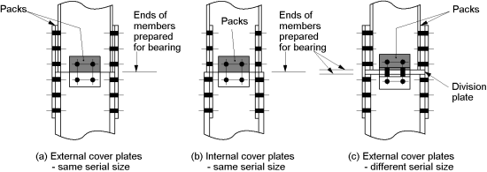
Column splices in multi-storey construction are required to provide strength and continuity of stiffness about both axes of the columns. Typical bolted column splices used for rolled I section and hollow section members are shown in the figure on the right.
Splices are typically provided every two or three storeys and are usually located approximately 600mm above floor level. This results in convenient lengths for fabrication, transport and erection, and gives easy access from the adjacent floor for bolting up on site. The provision of splices at each storey level is seldom economical since the saving in column material is generally far outweighed by the material, fabrication and erection costs of providing the splice.
[top]Bolted cover plate splices for I sections:
There are two categories for this type of connection:
- bearing type
- non-bearing type.
In the bearing type splice (see figure below) the loads are transferred in direct bearing from the upper shaft either directly or through a division plate. The 'bearing type' splice is the simpler connection, usually having fewer bolts than the non-bearing splice, and is therefore the one most commonly used in practice.
When no net tension is present, a standard connection can be used, however BS EN 1993-1-8[1] imposes the requirement for the splice plates and bolts to transmit at least 25% of the maximum compressive force in the column.
For bearing type splices, the tying resistance, required in Class 2b buildings, is likely to be the critical check.

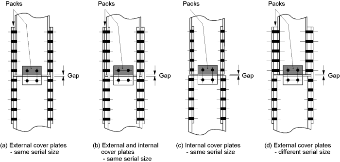
Splices categorised as non-bearing type (see figure below) transfer loads via the bolts and splice plates. Any direct bearing between the members is ignored, the connection sometimes being detailed with a physical gap between the two shafts. The design of a non-bearing splice is more involved, as all forces and moments must be transmitted through the bolts and splice plates. For non-bearing type splices, the minimum requirements in BS EN 1993-1-8[1] are very onerous, being based on member capacity rather than applied force.
As splices are generally provided just above floor levels the moment due to strut action is considered insignificant. The moments induced in splices placed at other positions, however, should be taken into account. AD 471 provides comprehensive advice on the calculation of the bending moments to be included in the splice design.

Column splices should hold the connected members in line, and wherever practical, the members should be arranged so that the centroidal axis of the splice material coincides with the centroidal axis of the column sections above and below the splice. If the column sections are offset (for example to maintain a constant external line) the moment due to the eccentricity should be accounted for in the joint design.
Design checks required for bolted cover plate column splices as well as procedures, worked examples, detailing requirements and design resistance tables are available in chapter 6 of the 'Green Book' (SCI P358).
[top]Bolted 'cap and base' or 'end plate' splices for tubular and rolled I sections


This type of splice, consisting of plates which are welded to the ends of the lower and upper columns and then simply bolted together on site, is commonly used in tubular construction but may also be used for open sections.
The most simple form of the connection is as shown in the figure right and is satisfactory as long as the ends of each shaft are prepared in the same way as for a bearing type splice. The possibility of load reversal should be considered, in addition to stability during erection and tying requirements.
Although commonly used, it is difficult to demonstrate that cap and base splices meet the requirements of BS EN 1993-1-8[1] clause 6.2.7.1(14). If these types of splices are used, common practice is to ensure that the plates are thick, and that bolts are located close to the flanges to increase the stiffness of the connection. Extended plates, with bolts outside the profile of the section may be used. If cap and base plate splices are located away from a point of restraint, special consideration should be given to ensuring adequate stiffness so that the member design is not invalidated.
'Cap and base' or 'end plate' column splices are covered in chapter 6 of the 'Green Book' (SCI P358). Detailing requirements, design procedures, worked examples and design resistance tables are given.
[top]Column bases


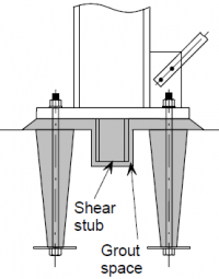
Typical column bases, as shown in the figure on the right, consist of a single plate fillet welded to the end of the column and attached to the foundation with four holding down bolts. The bolts are cast into the concrete base in location tubes or cones and are fitted with anchor plates to prevent pull out. High strength grout is poured into the space below the plate (see the figure below).
Such column bases are often only subject to axial compression and shear. However, uplift and horizontal shear may be a design case for column bases in braced bays.


Column base connection

A simple rectangular or square base plate is almost universally used for columns in simple construction. The base plate should be of sufficient size and strength to transmit the axial compressive force from the column to the foundation through the bedding material, without exceeding the local bearing resistance of the foundation.
A Base plate design tool is available.
Column bases are generally designed to transfer the force from the column to the base plate in direct bearing. Holding down systems are designed to stabilise the column during construction, and resist any uplift in braced bays. In some cases it is assumed that modest horizontal shear is also carried by the holding down bolts.
[top]Horizontal shear transfer
The way in which horizontal shear forces are transferred to the foundation is not well researched. Some designers check the resistance of the holding down bolts, and ensure that they are adequately grouted. This practice has been successfully followed for portal frame bases, which carry a significant shear.
Braced bays may have relatively high shear forces. Designers may opt to provide a shear stub welded to the underside of the base plate, though the recess may complicate the casting of the foundation, and special attention must be paid to the grouting operation. Design methods that cover this type of detail are given in the 'Green Book' (SCI P398).
Shear between the column end and the base plate will be transmitted by welds between the column and the base plate. Welds may be provided to the web only, or around parts of the profile - it is generally found that the weld resistance is more than adequate for modest shear forces.
[top]Bracing connections


Bracing members include flats, angles, channels, I sections, and hollow sections. Bracing arrangements may involve the bracing members working in tension alone, or in both tension and compression. In most cases, the bracing member is attached by bolting to a gusset plate, which is itself welded to the beam, to the column, or more commonly welded to the beam and its end connection as shown in the figure right.
Bracing systems are usually analysed assuming that all forces intersect on member centrelines. However, realising this assumption in the connection details may result in a connection with a very large gusset plate, especially if the bracing is shallow or steep. It is often more convenient to arrange the member intersections to make a more compact joint and check locally for the effects of eccentricities which are introduced.
Bracing connections are generally made with non-preloaded bolts in clearance holes. In theory at least, this allows some movement in the connection, but in practice this is ignored in orthodox construction. In some cases it may be that movement on reversal is unacceptable - preloaded connections should be used in these circumstances.
The general design process is:
- Identify the load path through the connection
- Arrange the connection to ensure that the design intent of the members is realised, e.g. the beam connections remain nominally pinned
- Include the effects of any significant eccentricity
- Check the components in the connection.
Pinned connection for a tubular bracing member
Design rules to determine the resistance of the gusset plate are given in 'Green Book' (SCI P358).
A Gusset plate design tool is also available.
[top]Special connections
Steelwork connections for simple construction, illustrated above, will generally produce the most economic steel frame. A departure from these connections will inevitably result in an increase in overall cost. The increase in detail drawing, fabrication and erection costs can be more than 100% if non standard connections form the majority of the connections used.
The need for special connections can often be avoided by judicious selection of member sizes. A minimum weight structure is unlikely to be the most cost effective. It is therefore good economic practice to ensure that steelwork can be placed with centrelines on established grids. The top flanges of beams should, where possible, be at a constant level, but this is less critical to cost than eccentric connections.
When designing special connections, it may be possible to use a modified version of one of the standardised connections given in the Green Book, subject to additional design checks. Design principles and component sizing rules given in the Green Book should be incorporated in connection design as much as possible.
Typical examples of situations where special connections are required are presented in the 'Green Book' (SCI P358).
[top]References
- ↑ 1.0 1.1 1.2 1.3 1.4 1.5 1.6 1.7 BS EN 1993-1-8:2005. Eurocode 3: Design of steel structures. Design of joints, BSI
- ↑ 2.0 2.1 2.2 NA to BS EN 1993-1-8:2005. UK National Annex to Eurocode 3: Design of steel structures. Design of joints, BSI
- ↑ ECCS Publication No. 126 European Recommendations for the Design of Simple Joints in Steel Structures. J. P. Jaspart et al. 2009.
- ↑ BS EN 1991-1-7:2006+A1:2014. Eurocode 1: Actions on structures. General actions. Accidental actions. BSI
- ↑ NA+A1:2014 to BS EN 1991-1-7:2006+A1:2014. UK National Annex to Eurocode 1: Actions on structures. General actions. Accidental actions. BSI
[top]Further reading
- Steel Designers' Manual 7th Edition. Editors B Davison & G W Owens. The Steel Construction Institute 2012, Chapter 27
- Architectural Design in Steel – Trebilcock P and Lawson R M published by Spon, 2004
[top]Resources
- SCI P358 Joints in Steel Construction - Simple Joints to Eurocode 3, 2014
- SCI P213 Joints in Construction - Composite Connections, 1998
- SCI P391 Structural Robustness of Steel Framed Buildings, 2011
- SCI P398 Joints in steel construction: Moment-resisting joints to Eurocode 3, 2013
- National Structural Steelwork Specification (7th Edition), 2020, (Publication No. 62/20), BCSA
- Commentary (3rd edition) on the National Structural Steelwork Specification for Building Construction (7th edition), 2022, (Publication No. 66/22), BCSA
- Architectural Teaching Resource. Studio Guide. SCI 2003
- SCI P183 Design of Semi-Continuous Braced Frames, 1997
- SCI P263 Wind-moment Design of Low Rise Frames, 1999
Connection design tools:
[top]See also
- Multi-storey office buildings
- Cost of structural steelwork
- Sustainability
- Steel construction products
- Braced frames
- Composite construction
- Design codes and standards
- Modelling and analysis
- Moment resisting connections
- Structural robustness
- Fabrication
- Welding
- Accuracy of steel fabrication
- Construction
- Preloaded bolting