


Preloaded bolting
Bolting is generally preferred for the site connections in short and medium span steel bridges because it can be carried out more quickly than welding, and with less interruption to the flow of erection. Installation and tightening of bolts is a major site activity and the designer should consider the access for operatives and equipment. If insufficient attention is paid, the result can be components that cannot be fitted or bolts that cannot be tightened with standard equipment.
Permanent bolted connections of structural parts of bridge steelwork are almost always made with preloaded bolts, as recommended in BS EN 1993-2[1]. Such connections are designed in shear as slip-resistant connections, such that they do not slip at either the serviceability limit state or the ultimate limit state (the choice being a matter for design). Traditionally such connections have been known in the UK as high strength friction grip (HSFG) connections.
Preloaded bolts are seldom used in buildings, where fatigue and slip in service are less critical. However, they may be used where oversized or slotted holes are used to increase tolerances during assembly.

[top]High-strength structural bolting assemblies for preloading
The design rules in BS EN 1993-1-8[2] for preloaded bolted connections relate to the use of bolts in accordance with BS EN 14399[3]. That standard has 10 separate parts; of particular note are:
- Part 3: System HR – Hexagon bolt and nut assemblies[4]
- Part 4: System HV – Hexagon bolt and nut assemblies[5]
- Part 9: System HR or HV – Direct tension indicators for bolt and nut assemblies[6]
- Part 10: System HRC – Bolt and nut assemblies with calibrated preload[7]
Direct tension indicators (DTI) are equivalent to ‘load indicating washers’ and system HRC is effectively the same as Tension Control Bolts (TCBs).
Currently only system HR (High Resistance) and HRC (High Resistance Calibrated) assemblies are used in the UK. System HV (Hochfest Vorgespannte Verbindung) assemblies have a short bolt thread and use a thinner nut to obtain ductility by plastic deformation of the threads within the nut. Both HR and HRC assemblies achieve the necessary ductility primarily by plastic deformation of the bolt threads. These systems of bolting are less susceptible to overtightening during preloading. However, if these assemblies are overtightened, the ductile failure mode is by yielding and eventually fracture of the bolt. This type of failure is easily detectable. The use of both HR/HRC and HV systems on the same site should always be avoided because of the risk of confusion and misuse.
System HR assemblies are available in M12 to M36 diameter in property class 8.8 or 10.9. Generally, property class 8.8 sizes M24 and M30 are used in bridgework; these are readily available. System HRC (or TCBs) are available from M12 to M36 in property class 10.9 only, and sizes M24 and M30 are readily available for bridgework. Both HR and HRC are usually supplied in the UK as k-class K0 only (no specific k factor or torque value required). See later section on Installation of preloaded bolts for discussion of k-class).
Countersunk head preloaded bolts are available as system HR and HRC (or TCBs) but these should not normally be used, except where a flush finish is essential for functional (not aesthetic) reasons.
Weathering grade bolting assemblies are not specifically covered in the BS EN 14399[3] series. The execution standard BS EN 1090-2[8] section 5.6.6 gives advice in regard to suitable fasteners, but there is limited availability of such bolting assemblies in the UK. System HR weathering grade assemblies are available in property class 8.8, M24 diameter only. System HRC (or TCBs) are available in property class 10.9, M24 and M30 diameter; availability of any stock should always be sought from suppliers.
[top]Slip-resistant connections
Slip-resistant connections depend for their performance on the tightening of preloaded bolts to a specified minimum preload and a friction coefficient for the faying (interface) surfaces. The level of preload in a bolt is governed by three things:
- The tensile strength of the bolt material, the ‘property class’;
- The thread size of the bolt;
- The extent to which the bolt is strained (extended) during the installation and tightening process.
Frictional resistance is highly dependent on the surface conditions. Four classes of friction surface are defined in BS EN 1993-1-8[2] and slip factors given for each. The surface treatment that may be assumed for each of these classes is given in BS EN 1090-2[8] and is reproduced below.
| Surface treatment | Class | Slip factor (μ) |
|---|---|---|
| Surfaces blasted with shot or grit with loose rust removed, not pitted | A | 0.50 |
| Surfaces hot-dip galvanized and flash (sweep) blasted and with alkali-zinc silicate paint with a nominal thickness of 60 μm | B | 0.40 |
| Surfaces blasted with shot or grit; a) coated with alkali-zinc silicate paint with a nominal thickness of 60 μm+ b) thermally sprayed with aluminium or zinc or a combination of both to a nominal thickness not exceeding 80 μm |
B | 0.40 |
| Surfaces hot-dip galvanized and flash (sweep) blasted | C | 0.35 |
| Surfaces cleaned by wire brush or flame cleaning, with loose rust removed | C | 0.30 |
| Surfaces as rolled | D | 0.20 |
+See AD 383 & AD 429 for further details.
If the friction surface has any other surface treatment, the slip factors must be established by slip tests, as described in Annex G of BS EN 1090-2[8].

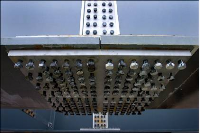
(Image courtesy of Mabey Bridge Ltd.)
Weathering steel is not explicitly mentioned in the above surface treatments and this might give rise to some uncertainty as to whether surfaces of weathering steel might suffer any reduction in slip factor over time, before the joint is bolted up. Research into this by Lark R.J[9]. has demonstrated that there is no reduction in slip factor after 40 days and indeed the slip coefficient marginally improved through exposure. The research also demonstrates that for carbon steel grades there is no appreciable reduction in slip factor at 40 days of exposure.
Before assembly of the joint at site, any contamination of the slip resistant surfaces by oil or grease must be removed by suitable chemical means, as flame cleaning usually leaves harmful residues. If the joint cannot be assembled as soon as the surfaces have been treated, or as soon as any protective masking has been removed, it is sufficient to remove any thin film of rust or other loose material with a wire brush. During this process, the surfaces must not be damaged or made smooth.
Moisture on a face, in the form of clean water, rain or dew, should not be a problem unless it washes in dirt or is present for so long that serious rusting occurs. Light rusting is not detrimental to the performance of the joint.
[top]Installation of preloaded bolts
For the installation of preloaded bolts, steelwork contractors should employ a certificated bolting coordinator and appropriately trained operatives, in accordance with the requirements of NHSS 20[10], and the BCSA Standard for Competence in Preloaded Bolting.
BS EN 1090-2[8] gives requirements for four methods of tightening preloaded bolts. Each method is intended to achieve at least the minimum preload. These four methods are;
In addition, the Specification for Highway Works[11] gives requirements for tightening by the 'part-turn method'. Those requirements are similar to those for the HSFG bolts that have been used in the UK for very many years, before the introduction of BS EN 14399[3].
The suitability for preloading is determined by tests in accordance with BS EN 14399-2[12], which demonstrate the rotation/bolt force relationship for the assembly. Some of the tightening methods rely on the ‘k-class’ of the assembly, determined according to the relevant Part of BS EN 14399[3]; the class depends on the characteristics of the rotation/bolt force curves. Three classes are defined, K0, K1 and K2. The classes required for the various methods of tightening are shown below. This table is based on Table 19 of BS EN 1090-2[8], with the addition of the class requirement for the part-turn method.
| Tightening method | k-classes |
|---|---|
| Torque method | K2 |
| Combined method | K2 or K1 |
| HRC method | K0 with HRD nut only or K2 |
| Direct tension indicator (DTI) method | K2, K1 or K0 |
| Part turn method | K0 |
The as-delivered calibration (k-class) is valid for tightening by rotation of the nut. If tightening is done by rotation of the bolt head, calibration in accordance with Annex H of BS EN 1090-2[8] or by supplementary testing in accordance with BS EN 14399-2[12] is required.
Currently, only class K0 assemblies are manufactured in the UK. There may be supply issues if a method that requires class K1 or K2 is selected.
[top]General

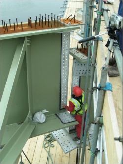
(Image courtesy of Mabey Bridge Ltd.)
All tightening methods need the components to be brought together to a snug-tight condition before commencement of preloading. Whichever method of bolt tightening is chosen bolts and nuts should always be tightened in a staggered pattern. When a bolt group comprises more than four bolts, tightening should be from the middle of the joint outwards and ensuring that all the plies are properly pulled together in full contact. Any residual gaps at the edges should not exceed 2 mm at this stage.
Tightening is performed by rotation of the nut, except where the access to the nut side of the assembly is inadequate. Special precautions, depending on the tightening method adopted, may have to be taken when bolts are tightened by rotation of the bolt head.
Pre-tightening and subsequent tightening are carried out progressively from the most rigid part of the joint to the least rigid part. To achieve uniform preloading, more than one cycle of tightening may be necessary. Pre-tightening should be completed for all bolts in a connection prior to commencement of subsequent steps.
If due to any cause a bolt or nut is slackened off after final tightening, the bolt, nut and washer must be discarded and not reused.
[top]Torque method
The torque method is a two-stage operation, bedding in following by tightening. Tightening is always done in two steps, ‘Initial Torque’ and ‘Final torque’ using a calibrated torque wrench. This can be either a manual wrench or power tool fitted with a torque cut-out that must first be calibrated on a bolt from the job batch using a bolt load meter or similar device for determining bolt tension.
The procedure in BS EN 1090-2[8] requires the test bolt to be tightened to a calculated load related to the minimum shank tension, and the torque setting to obtain this tension is then used for tightening the bolts in the structure. It must be appreciated that torque can vary considerably (as much as ± 30% and even more if the bolts are coated) from bolt to bolt, even within the same batch, depending on a number of factors including the condition of the threads and nut/washer interface, and the amount of lubricant present on the threads. The result is an erratic torque-tension relationship and an unreliable preload.
The torque wrench is required by BS EN 1090-2[8] to have an accuracy of ± 4 % according to BS EN ISO 6789[13] (all parts). Each wrench must be checked for accuracy at least weekly, and in the case of pneumatic wrenches, every time the hose length is changed. Torque wrenches used in the first tightening step only need to have an accuracy of ± 10 % and checked yearly. However, it is deemed good practice that the wrench be calibrated at least once per shift, or more often if required by the contract supervisor, for each change of diameter or batch and as specified for changes in bolt lengths. The reference torque for tightening depends on the K class.
[top]Combined method
After bedding in, tightening using the combined method is again a two step process. Initial tightening is similar to the torque method and a torque wrench with an accuracy of only ± 10 % is used. A second tightening step then follows, in which a specified part turn is applied to the rotated part of the assembly. The position of the nut relative to the bolt threads is marked after the first step, using a marking crayon or marking paint, so that the final rotation of the nut relative to the thread in this second step can be easily determined. Values for the required amount of part turn are given in BS EN 1090-2[8].
[top]HRC method
HRC assemblies are tightened using a special wrench equipped with two co-axial sockets that react one against the other. The outer socket, which engages the nut, rotates clockwise. The inner socket, which engages the spline end of the bolt, rotates anticlockwise. The detailing of a ‘break-neck’ below the spline is such that it will shear off at a predetermined torque.
It is not necessary to calibrate the wrench in this case because the strength of the break-neck determines the maximum torque. However, the actual preload induced depends on the torque / preload relationship and this is partly related to the thread friction. The variability of the friction is controlled by supplying the bolts in drums to protect them from weather and contamination, but the lubrication can be affected by rain once the bolts are in place and ready to be tightened.
After bedding in, a two-step process is used to tighten each bolt. In step 1 the bolt assembly is tightened until the outer socket stops turning (this is evident by a change in the sound of shear wrench). This step is completed for all the bolts in the connections before proceeding to step 2. In step two the full preload is achieved when all the spines have sheared off
[top]Direct tension indicator (DTI) method
Direct tension indicators are specially hardened washers with nibs on one face. The nibs bear against the underside of the bolt head leaving a gap between the head and the load indicating face. Provision can be made for the DTI to be fitted under the nut when this is more convenient using a nut faced washer and tightening the bolt by rotating the head.
The compressible nibs deform to indicate when the minimum preload has been achieved. To reach a uniform "snug-tight" condition, there is no significant deformation of the DTI protrusions. In step 1 of the tightening process, the bolt assembly is tightened until the nibs just begin to deform. Once again, this step should be applied to all bolts in the connections before commencing the second step. In step 2, each bolt assembly is tightened until the protrusions are compressed and the gaps meet certain conditions specified in BS EN 1090-2[8].
DTIs are available in steel with improved atmospheric corrosion resistance (i.e. weathering steel) but their use is prohibited by BS EN 1090-2[8] because crevices are created that would become corrosion traps. When used on painted bridges, the gaps in the DTIs have to be sealed by hand prior to painting in accordance with the Highways Agency Specification for Highway Works, Series 1900[14]
[top]Part-turn method
The part turn method is similar to the combined method except that much greater reliance is placed on the rotation and less on the torque. Because it relies mainly on the rotation to achieve a particular strain and thus preload, the method does not require the use of K1 or K2 class assemblies. The method set out in the Specification for Highway Works[11] has been validated for property class 8.8 bolts of sizes M24 and M30.
Tightening by the part-turn method comprises two steps:
1. A first tightening step, using a torque wrench. The wrench is set to a torque value in accordance with the table below. This first step must be completed for all bolts in one connection prior to commencement of the second step.
| Nominal diameter (mm) |
Bedding torque of bolt ± 10% (Nm) |
|---|---|
| 24 | 270 |
| 30 | 460 |
2. A second final tightening step in which a specified part turn is applied to the turned part of the assembly. The position of the nut relative to the bolt threads is marked permanently after the first step, so that the final rotation of the nut relative to the thread in this second step can be easily determined. The second step is in accordance with the values given below.
| Total nominal thickness “t” of parts to be connected (inclusive of all packers and washers) | Further angle of rotation to be applied during the second stage of tightening | |
|---|---|---|
| Degrees | Part-turn | |
| t ≤ 160 mm | 180 | ½ |
The main advantage of part-turn tightening is that it is a strain control method and is therefore almost totally independent of the friction and torque characteristics of the nut and bolt assembly. The part-turn method induces a specific strain (related to the part turn and thread pitch) that is well in excess of the elastic limit and which takes the bolt into a region where the load-elongation curve is relatively flat and thus the variations in (the relatively modest) bolt load applied during bedding result in only minor variations in the preload of the installed bolt.
This consistency provides the following benefits to the steelwork contractor and the client:
- Predictability: Preload always exceeds the minimum specified
- Reliability: Simple to control and supervise on site
- Economy: No calibration on site and less risk of re-work, so lower costs
- Versatility: Suitable for both non-alloy steel and weathering steel bridges
[top]Inspection
A significant part of the cost of using preloaded bolts is related to the inspection. This is the key to the effective use of preloaded bolts, so should be carried out strictly in accordance with the requirements of BS EN 1090-2[8], or with the clauses from the Specification for Highway Works[11] for the part turn method.
[top]References
- ↑ BS EN 1993-2:2006, Eurocode 3. Design of steel structures. Steel bridges, BSI
- ↑ 2.0 2.1 BS EN 1993-1-8:2005, Eurocode 3. Design of steel structures. Design of joints, BSI
- ↑ 3.0 3.1 3.2 3.3 BS EN 14399, High-strength structural bolting assemblies for preloading, (Various parts), BSI
- ↑ BS EN 14399-3:2015, High-strength structural bolting assemblies for preloading. System HR. Hexagon bolt and nut assemblies, BSI
- ↑ BS EN 14399-4:2015, High-strength structural bolting assemblies for preloading. System HV. Hexagon bolt and nut assemblies, BSI
- ↑ BS EN 14399-9:2018, High strength structural bolting assemblies for preloading. System HR or HV. Direct tension indicators for bolt and nut assemblies, BSI
- ↑ BS EN 14399-10:2018, High-strength structural bolting assemblies for preloading. System HRC. Bolt and nut assemblies with calibrated preload, BSI
- ↑ 8.00 8.01 8.02 8.03 8.04 8.05 8.06 8.07 8.08 8.09 8.10 8.11 BS EN 1090-2:2018, Execution of steel structures and aluminium structures. Technical requirements for steel structures, BSI
- ↑ Lark, R J, 2004, HSFG bolted connections using weathering steel materials, Proceedings of the Institution of Civil Engineers, Bridge Engineering 157 (BE2).
- ↑ NHSS 20: National Highways Sector Schemes for Quality Management in Highway Works, 20. The Execution of Steelwork in Transportation Infrastructure Assets, Issue 6 (9001:2015), February 2023
- ↑ 11.0 11.1 11.2 Manual of Contract Documents for Highway Works (MCHW). Volume 1: Specification for Highway Works. Series 1800 Structural Steelwork. April 2021, TSO
- ↑ 12.0 12.1 BS EN 14399-2:2015, High-strength structural bolting assemblies for preloading. Suitability for preloading, BSI
- ↑ BS EN ISO 6789:2017, Assembly tools for screws and nuts. Hand torque tools (Various parts), BSI
- ↑ Manual of Contract Documents for Highway Works: Volume 1 - Specification for Highway Works, Series 1900 Protection of steelwork against corrosion, August 2014, The Stationery Office
[top]Resources
- BCSA Standard - Competence in Preloaded Bolting, 2012
- Steel Bridges: A practical approach to design for efficient fabrication and construction, 2010, (Publication no. 51/10), BCSA
- Hydrogen Embrittlement - Its effect on Structural Bolting Assemblies, 2022, BCSA
- Hendy, C.R.; Iles, D.C. (2015) Steel Bridge Group: Guidance Notes on best practice in steel bridge construction (6th Issue). (P185). SCI