


Moment resisting connections
This article considers moment resisting connections which are used in the design of single-storey and multi-storey buildings, in which continuous frames are used.
The article discusses the types of moment resisting connections that are most commonly used. The use of standard connections for beam-to-column and beam-to-beam connections is considered and an overview of the design procedures, based on Eurocode 3 is presented. Both bolted and welded connections are considered. Column splices and column bases are also presented.

[top]Types of moment resisting connections
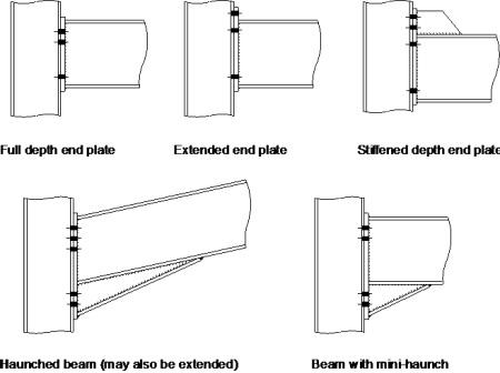
Moment resisting connections are used in multi-storey un-braced buildings and in single-storey portal frame buildings. Connections in multi-storey frames are most likely to be bolted, full depth end plate connections or extended end plate connections. Where a deeper connection is required to provide a larger lever-arm for the bolts, a haunched connection can be used. However, as extra fabrication will result, this situation should be avoided if possible.
For portal frame structures, haunched moment resisting connections at the eaves and apex of a frame are almost always used, as in addition to providing increased connection resistances, the haunch increases the resistance of the rafter.
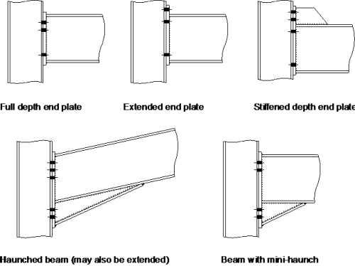
The most commonly used moment resisting connections are bolted end plate beam-to-column connections; these are shown in the figure below.
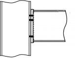
Full depth end plate
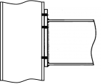
Extended end plate
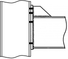
Stiffened extended end plate
Haunched beam


Instead of bolted beam-to-column connections, welded connections can be used. These connections can provide full moment continuity but are expensive to produce, especially on site. Welded beam-to-column connections can be prepared in the fabrication workshop with a bolted splice connection within the beam spam, at a position of lower bending moment. Welded connections are also used for the construction of buildings in seismic areas.
Other types of moment resisting connections include:
- Splices in columns and beams, including apex connections in portal frames, and
- Column bases.
One aspect that is not covered in this article is welded joints between
hollow sections. Guidance on the design of welded joints between hollow sections is given in BS EN 1993-1-8[1]. Manufacturers such as Tata Steel also provide guidance.
[top]Joint classification
Design of joints in steel structures in the UK is covered by BS EN 1993-1-8[1] and its National Annex[2].
BS EN 1993-1-8[1] requires that joints are classified by stiffness (as rigid, semi-rigid or nominally pinned) or by strength (as full strength, partial strength or nominally pinned). The stiffness classification is relevant for elastic analysis of frames, the strength classification is for frames analysed plastically. The Standard defines joint models as simple, semi-continuous or continuous, depending on stiffness and strength. Moment-resisting joints will usually be rigid and either full or partial strength and thus the joints are either continuous or semi-continuous.
In most situations, the design intent would be that moment-resisting joints are rigid, and modelled as such in the frame analysis. If the joints were in fact semi-rigid, the behaviour of the joint would need to be taken into account in the frame analysis but the UK NA[2] discourages this approach until experience is gained with the numerical method of calculating rotational stiffness.
Clause 5.2.2.1(2) of BS EN 1993-1-8[1] notes that a joint may be classified on the basis of experimental evidence, experience of previous satisfactory performance in similar cases or by calculations based on test evidence.
The UK National Annex[2] offers further clarification, and in NA.2.6 comments that connections designed in accordance with SCI P207[3]. (the BS 5950 version of the Green Book on moment connections) may be classified in accordance with the recommendations in that publication.
SCI P207[3] has been updated to take account of BS EN 1993-1-8[1] and has been reissued as SCI P398 .
[top]Rigid joint classification
Well-proportioned connections that follow the recommendations for standardisation given in SCI P398 and designed for strength alone can generally be assumed to be rigid for joints in single-storey portal frames. For multi-storey unbraced frames, rotational stiffness is fundamental to the determination of frame stability. The designer must therefore either evaluate connection stiffness (in accordance with BS EN 1993-1-8[1]) and account for this in the frame design and assessment of frame stability or, if rigid joints have been assumed in the frame analysis, ensure that the connection design matches this assumption. For an end plate connection, it may be assumed that the connection is rigid if both the following requirements are satisfied:
- Adopting relatively thick end plates and potentially a stiffened column flange
- The column web panel shear force does not exceed 80% of the design shear resistance. If this is not possible, a stronger column should be used, or suitable strengthening should be provided.
Where a rigid joint cannot be assumed, the joint should be assumed to be 'semi-rigid' and the flexibility of the joints allowed for in the frame analysis.
[top]Costs
Moment-resisting joints are invariably more expensive to fabricate than simple (shear only) connections . Although the material cost of the components in the connection (the plates, the bolts etc) may not be significant, moment-resisting joints generally involve more welding than other connections. Welding is an expensive operation and also involves inspection after completing the welds.
Local strengthening adds further expense: increasing the resistance of the main members should always be considered as a cost-effective alternative. Local strengthening often makes the connections to the minor axis more difficult to achieve, adding further cost.
Haunches involve a large amount of welding and are therefore expensive. When used to increase the resistance of the member, such as in a portal frame rafter, their use is justified, but haunches can be an expensive option if provided only to make a bolted connection feasible.
[top]Standard connections
Although there are no standard moment-resisting connections, the principles of standardisation remain important for structural efficiency, cost-effective construction and safety. The following guidance is generally recommended, at least for initial design purposes:
- M20 or M24 property class 8.8 bolts, fully threaded
- Bolts at 90 or 100 mm cross-centres ('gauge')
- Bolts at 90 mm vertical centres ('pitch')
- S275 or S355 fittings (end plates, splice plates and stiffeners)
- 20 mm end plates with M20 bolts; 25 mm end plates with M24 bolts.
[top]Bolted beam-to-column connections
Bolted end plate joints between I-section or H-section beams and columns as shown in the figure below are designed using the approach described in BS EN 1993-1-8[1]. Bolted end plate splices and apex connections, which use similar design procedures, are covered in the section on splices.
[top]Design basis


The resistance of a bolted end plate connection is provided by a combination of tension forces in the bolts adjacent to one flange and compression forces in bearing at the other flange. Unless there is axial force in the beam, the total tension and compression forces are equal and opposite. Vertical shear is resisted by bolts in bearing and shear; the force is usually assumed to be resisted mainly by bolts adjacent to the compression flange. These forces are illustrated diagrammatically in the figure on the right.
At the ultimate limit state, the centre of rotation is at, or near, the compression flange and, for simplicity in design, it may be assumed that the compression resistance is concentrated at the level of the centre of the flange.
The bolt row furthest from the compression flange will tend to attract the greatest tension force and design practice in the past has been to assume a 'triangular' distribution of forces, pro rata to the distance from the bottom flange. However, where either the column flange or the end plate is sufficiently flexible (as defined by NA.2.7 of the UK NA[2]) that ductile behaviour is achieved, the full resistances of the lower rows may be used (this is sometimes referred to as a 'plastic distribution of bolt row forces').
- Distribution of forces in the bolts

Triangular distribution

‘Plastic’ distribution


[top]Design method
The full design method for an endplate connection is necessarily an iterative procedure: a configuration of bolts and, if necessary, stiffeners are selected; the resistance of that configuration is evaluated; the configuration is then modified for greater resistance or greater economy, as appropriate; the revised configuration is re-evaluated, until a satisfactory solution is achieved.
| STEP 1 | Calculate the effective tension resistances of the bolt rows. This involves calculating the resistance of the bolts, the end plate, the column flange, the beam web and the column web. The effective resistance for any row may be that for the row in isolation, or as part of a group of rows, or may be limited by a 'triangular' distribution from compression flange level.
|
| STEP 2 | Calculate the resistances of the compression zone of the column web, taking account of the shear force in the column web, and of the beam flange. |
| STEP 3 | Calculate the shear resistance of the column web. |
| STEP 4 | If the total tension resistance exceeds the compression resistance, (Step 2) or column web shear resistance (Step 3), calculate reduced effective tension resistances for the bolt rows, where necessary to ensure equilibrium.
|
| STEP 5 | Calculate the shear resistance of the bolt rows. The resistance is taken as the sum of the full shear resistance of the bottom row (or rows) of bolts (which are not assumed to resist tension) and 28% of the shear resistance of the bolts in the tension zone (assuming, conservatively, that they are fully utilized in tension). |
| STEP 6 | Verify the adequacy of any stiffeners in the configuration. |
| STEP 7 | Verify the adequacy of the welds in the connection. (Note that welds sizes are not critical in the preceding Steps).
|


The verification of the resistance of a welded end plate connection considering each of the components that make up the connection is illustrated in the figure right and accompanying table below.
| Zone | Ref | Component | Procedure |
|---|---|---|---|
| Tension | a | Bolt tension | Step 1a |
| b | End plate bending | Step 1a | |
| c | Column flange bending | Step 1a | |
| d | Beam web tension | Step 1b | |
| e | Column web tension | Step 1b | |
| f | Flange to end plate weld | Step 7 | |
| g | Web to end plate weld | Step 7 | |
| Horizontal shear | h | Column web panel shear | Step 3 |
| Compression | j | Beam flange compression | Step 2 |
| k | Beam flange weld | Step 7 | |
| I | Column web | Step 2 | |
| Vertical shear | m | Web to end plate weld | Step 7 |
| n | Bolt shear | Step 5 | |
| p | Bolt bearing (plate or flange) | Step 5 |
The calculations corresponding to the design steps set out above are described comprehensively in SCI P398 Section 2.5.
[top]Methods of strengthening
Careful selection of the members during design will often avoid the need for strengthening of the joint, and will lead to a more cost-efficient structure. Sometimes, however, there is no alternative to strengthening one or more of the connection zones. The range of stiffeners which can be employed is shown in the figures below.


The type of strengthening must be chosen such that it does not clash with other components at the connection. This is often a problem with conventional stiffeners when secondary beams connect into the column web.
There are usually several ways of strengthening each zone and many of them can contribute to overcoming a deficiency in more than one area, as shown in the table below.
| Type of column stiffener | Deficiency | ||||||
|---|---|---|---|---|---|---|---|
| Web in tension | Flange in bearing | Web in compression | Web in shear | ||||
|
• | • | • | ||||
| • | • | • | |||||
| Supplementary web plates | • | • | • | ||||
| Diagonal stiffeners (N & K) | • | • | • | ||||
| Morris stiffeners | • | • | • | ||||
| Flange backing plates | • | ||||||
[top]Welded beam-to-column connections
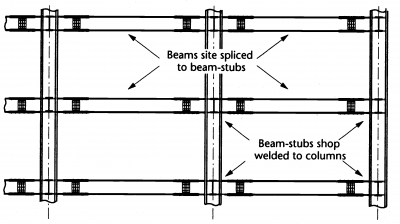
The intention with shop welded construction is to ensure that the main beam-to-column connections are made in a factory environment and can be full strength rigid joints. To achieve this, while still keeping the piece sizes small enough for transportation, short stubs of the beam section are welded to the columns. The connection of the stub to the rest of the beam is normally made with a bolted cover plate splice. Note that the bolted splices should use preloaded bolt assemblies if slip in the connection is to be avoided.
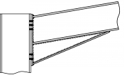
A typical arrangement for a multi-storey building is shown in the figure below.

[top]Shop welded connections


A typical factory welded connection, as shown in the figure on the right, consists of a short section beam stub factory welded on to the column flanges, and a tapered stub welded into the column inner profile on the other axis. The stub sections are prepared for bolting or welding with cover plates usually at a location where the bending moment has reduced.
The benefits of this approach are:
- Efficient, full strength moment connections - all the welding to the column is carried out under controlled conditions
- The work piece can be turned to avoid or minimize positional welding.
The disadvantages are:
- More connections and therefore higher fabrication costs
- The 'Column Tree' stubs make the component difficult to handle and transport
- The beam splices have to be bolted or welded in the air some distance from the column
- The flange splice plates and bolts may interfere with some types of flooring such as pre-cast units or metal decking.
[top]Practical considerations

Continuous fillet welds are the usual choice for most small and medium sized beams with flanges up to 17 mm thick. However, many steelwork contractors prefer to switch to partial penetration butt welds with superimposed fillets, or full penetration butt welds, rather than use fillet welds larger than 12 mm.
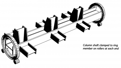
To help provide good access for welding during fabrication, the column shafts can be mounted in special manipulators and rotated to facilitate welding in a down hand position to each stub.
[top]Design method
In statically determinate frames, a partial strength connection, adequate to resist the design moment is satisfactory. If the frame is statically indeterminate, the connections must have sufficient ductility to accommodate any inaccuracy in the design moment arising, for example, from frame imperfections or settlement of supports. To achieve this, the welds in the connection must be made full strength.
| STEP 1 | Calculate the design forces in the tension and compression flanges of the beam. The presence of the web may be neglected when determining these forces. |
| STEP 2 | Calculate the resistances in the tension zone and verify their adequacy. If, for an unstiffened column, the resistances are inadequate, determine the resistance for a stiffened column and verify its adequacy. Column flange stiffeners will normally be required. |
| STEP 3 | Calculate the resistances in the compression zone and verify their adequacy. If, for an unstiffened column, the resistances are inadequate, determine the resistance for a stiffened column and verify its adequacy. |
| STEP 4 | Verify the adequacy of the column web panel in shear. If the unstiffened panel is inadequate, it may be stiffened, as for an end-plate connection . |
| STEP 5 | Verify the adequacy of the welds to the flanges and web. |


The verification of the resistance of a welded beam to column connection considering each of the components that make up the connection is illustrated in the figure on the right and listed in the accompanying table below.
| Zone | Ref | Component | Procedure |
|---|---|---|---|
| Tension | a | Beam flange | Step 2 |
| b | Column web | Step 2 | |
| Compression | c | Beam flange | Step 3 |
| d | Column web | Step 3 | |
| Horizontal shear | e | Column web panel shear | Step 4 |
| Welds | f, g | Flange welds | Step 5 |
| h | Web weld | Step 5 |
The calculations corresponding to design steps set out above are described comprehensively in SCI P398 Section 3.4.
[top]Splices
The design of beam and column splices between H or I sections that are subjected to bending moment, axial force and transverse shear force include the following types of joint:
- Bolted cover plate splices
- Bolted end plate splices
- Welded splices.
The design of bolted column splices that are subject to predominant compressive forces is covered in the simple connections article and in greater detail in SCI P358 .
[top]Bolted cover plate splices
[top]Connection details


Typical bolted cover plate splice arrangements are shown in the figure.
In a beam splice there is a small gap between the two beam ends. For small beam sections, single cover plates may be adequate for the flanges and web. For symmetric cross sections, a symmetric arrangement of cover plates is normally used, irrespective of the relative magnitudes of the design forces in the flanges.
Column splices can be either of bearing or non-bearing type. Design guidance for bearing type column splices is given in SCI P358. Non-bearing column splices may be arranged and designed as for beam splices.
[top]Design basis
A beam splice (or a non-bearing column splice) resists the coexisting design moment, axial force and shear in the beam by a combination of tension and compression forces in the flange cover plates and shear, bending and axial force in the web cover plates.
To achieve a rigid joint classification, the connections must be designed as slip resistant connections. It is usually only necessary to provide slip resistance at SLS (Category B according to BS EN 1993‑1‑8[1], 3.4.1) although if a rigid connection is required at ULS, slip resistance at ULS must be provided (Category C connection).
In elastically analysed structures, bolted cover plate splices are not required to provide the full strength of the beam section, only to provide sufficient resistance against the design moments and forces at the splice location. Note, however that when splices are located in a member away from a position of lateral restraint, the design bending moment must include the additional second order moments. Designers should refer to AD 471.
[top]Stiffness and continuity
Splices must have adequate continuity about both axes. The flange plates should therefore be, at least, similar in width and thickness to the beam flanges, and should extend for a minimum distance equal to the flange width or 225mm, on either side of the splice. Minimum requirements for strength are given in BS EN 1993-1-8[1] clause 6.2.7.1 (13) and (14). Designers should also refer to SCI Advisory Desk note AD393.
[top]Design method
The design process for a beam splice involves the choice of the sizes of cover plates and the configuration of bolts that will provide sufficient design resistance of the joint. The process has a number of distinct stages, which are outlined below.
| STEP 1 | Calculate design tension and compression forces in the two flanges, due to the bending moment and axial force (if any) at the splice location. These forces can be determined on the basis of an elastic stress distribution in the beam section or, conservatively, ignoring the contribution of the web.
|
| STEP 2 | Determine the bolt resistances and verify their adequacy, in the flanges and in the web. |
| STEP 3 | Verify the adequacy of the tension flange at the splice and the cover plates. |
| STEP 4 | Verify the adequacy of the compression flange at the splice and the cover plates. |
| STEP 5 | Ensure that there is a minimum resistance for continuity of the beam. |


The above steps involve the determination of resistance values of 11 distinct components of a bolted splice, as illustrated in the figure on the right and listed in the accompanying table below.
| Zone | Ref | Component | step |
|---|---|---|---|
| Tension | a | Flange cover plate(s) | 3 |
| b | Bolt shear | 2 | |
| c | Bolt bearing | 2 | |
| d | Flange | 3 | |
| Compression | e | Flange | 4 |
| f | Flange cover plate(s) | 4 | |
| g | Bolt shear | 2 | |
| h | Bolt bearing | 2 | |
| Shear | j | Web cover plate(s) | 1 |
| k | Bolt shear | 1 | |
| l | Bolt bearing | 1 |
The calculations corresponding to design steps set out above are described in detail in SCI P398 Section 4.2.
[top]Bolted end-plate splices
[top]Connection details
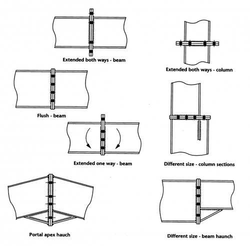

Bolted end plate connections, as splices or as apex connections in portal frames, are effectively the beam side of the beam-to-column connections, mirrored to form a pair. This form of connection has the advantage over the cover plate type in that preloaded bolts (and the necessary preparation of contact surfaces) are not required. However they are less stiff than cover plate splice details.
The 'portal apex haunch' splice is regularly used in single storey portal frames and is commonly assumed to be 'Rigid' for the purposes of elastic global analysis.
[top]Design method
The design method is essentially that described for beam-to-column connections, omitting the evaluation of column resistances. The relevant steps and the corresponding calculations are described in SCI P398 Section 4.3.
[top]Beam-through-beam moment connections
[top]Connection details
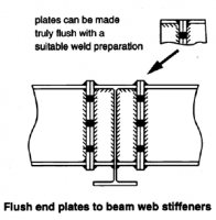
Beam-through-beam joints are usually made using end plate connections with non-preloaded bolts; typical details are shown in the figure below. Non-preloaded bolts may be used when there are only end plates but when a cover plate is used as well, preloaded bolts should be used, to prevent slip at ULS.
- Typical beam through beam splices


[top]Design method
Where there is no cover plate, the design method for end plate splices may be used. Where a cover plate is used, it should be designed as for a cover plate splice; it may be assumed conservatively that the end plate bolts carry only vertical shear.
The connection between the cover plate and the supporting beam is usually only nominal, as the moment transferred in torsion to the supporting beam is normally very modest.
The relevant steps and the corresponding calculations are described in SCI P398 Section 4.4.
[top]Welded splices
[top]Connection details
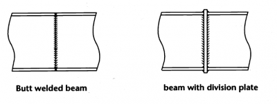

Welded shop splices are often employed to join shorter lengths delivered from the mills or stockists. In these circumstances the welds are invariably made 'full strength' by butt welding the flanges and the web. Small cope holes may be formed in the web to facilitate welding of the flange.
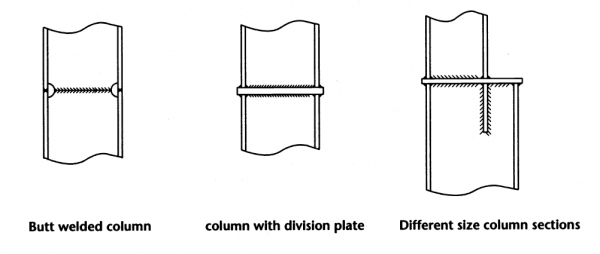

Where the sections being joined are not from the same 'rolling' and consequently vary slightly in size because of rolling tolerances, a division plate is commonly provided between the two sections. When joining components of a different serial size by this method, a web stiffener is needed in the larger section (aligned to the flange of the smaller section), or a haunch may be provided to match the depth of the larger size.
A site splice can be made with fillet welded cover plates, as an alternative to a butt welded detail. Bolts may be provided in the web cover plates for temporary connection during erection.
[top]Design basis
For welded splices the general design basis is:
- For statically indeterminate frames, whether designed plastically or elastically, full strength welds should be provided to the flanges and the web
- In statically determinate frames, splices may be designed to resist a design moment that is less than the member moment resistance, in which case:
- The flange welds should be designed to resist a force equal to the design moment divided by the distance between flange centroids.
- The web welds should be designed to resist the design shear.
- If there is an axial force it should be shared between the flanges and the welds designed for this force in addition to that due to the design moment.
The full strength requirement for indeterminate is needed to ensure that a splice is strong enough to accommodate any inaccuracy in the design moment, arising for example, from frame imperfections, modelling approximations or settlement of supports.
[top]Column bases


An example of a column base which is able to transmit moment and axial force between steel members and concrete substructures at the base of columns is shown in the figure on the left. The example shows a column base with an unstiffened base plate. Stiffened base plate connections and column bases cast in pockets are other options available. However, rigid base connections are not commonly used because of the associated foundation costs.
[top]Design basis
In terms of design, a column base connection is essentially a bolted end plate connection with certain special features:
- Axial forces are more important than is generally the case in end plate connections.
- In compression, the design force is distributed over an area of steel-to-concrete contact that is determined by the strength of the concrete and the packing mortar or grout.
- In tension, the force is transmitted by holding down bolts that are anchored in the concrete substructure.
As a consequence, an unstiffened base plate tends to be very thick, by comparison with end plates of beam-to-column connections.
More often than not, the moment may act in either direction and symmetrical details are chosen. However, there may be circumstances, e.g. some portal frames, in which asymmetrical details may be appropriate.
The connection will usually be required to transmit horizontal shear, either by friction or via the bolts. It is not reasonable that horizontal shear is distributed evenly to all the bolts passing through clearance holes in the base plate, unless washer plates are welded over the bolts in the final position. If the horizontal shear is large, a shear stub welded to the underside of the base plate may be more appropriate. In all cases, the grouting of the base is a critical operation, and demands special attention.
[top]Design method
The design process requires an iterative approach in which a trial base plate size and bolt configuration are selected and the resistances to the range of combined axial force and moment are then evaluation.
The relevant steps and the corresponding calculations are described in SCI P398 Section 5.5.
[top]Classification of column base connections
The rigidity of the base connection has generally greater significance on the performance of the frame than other connections in the structure. Most unstiffened base plates are substantially stiffer than a typical end plate detail. The thickness of the base plate and pre-compression from the column contribute to this. However, no base connection is stiffer than the foundation and, in turn, the soil to which its moment is transmitted. Much can depend on the characteristics of these other components, which include propensity to creep under sustained loading. The base connection cannot be regarded as 'rigid' unless the concrete base it joins is itself relatively stiff. Often this will be evident by inspection.
[top]References
- ↑ 1.0 1.1 1.2 1.3 1.4 1.5 1.6 1.7 1.8 1.9 BS EN 1993-1-8:2005. Eurocode 3: Design of steel structures. Design of joints, BSI
- ↑ 2.0 2.1 2.2 2.3 NA to BS EN 1993-1-8:2005. UK National Annex to Eurocode 3: Design of steel structures. Design of joints, BSI
- ↑ 3.0 3.1 P207 Joints in steel construction: Moment connections, SCI, 1995
[top]Further reading
- Steel Designers' Manual 7th Edition. Editors B Davison & G W Owens. The Steel Construction Institute 2012, Chapter 28
- Architectural Design in Steel – Trebilcock P and Lawson R M published by Spon, 2004
[top]Resources
- SCI P358 Joints in Steel Construction - Simple Joints to Eurocode 3, 2014
- SCI P398 Joints in Steel Construction - Moment-resisting Joints to Eurocode 3, 2013
- National Structural Steelwork Specification (6th Edition), Publication No. 57/17, BCSA 2017
- Steel Buildings in Europe. Single Storey Steel Buildings; Part 11: Moment Connections.
- Design of welded joints - Celsius®355 and Hybox®355, 2013, Tata Steel