


Framing schematics
Most forms of steel framing used in UK construction may be grouped as follows:
- Braced frames or 'simple' construction, in which the beams and columns are designed to resist vertical loads only. The connections are designed as nominally pinned.
- Rigid or continuous frames, in which the framed structure is designed so that the connections between the members are moment-resisting.
- Arch structures, in which forces are transferred to the ground, mainly by compression within the structure.
- Tension structures, in which forces are transferred to the ground by tension (or catenary action) and by compression in posts or masts, as in a tent.
Braced frames with nominally pinned connections and vertical bracing (which may be steel bracing or a concrete core) offer a very cost-competitive structural solution, and are the most commonly used structural system in buildings. Rigidly framed structures are preferred if there is no opportunity for the use of vertical bracing, such as in fully glazed facades or in large-span structures. In braced frames, columns are designed to resist mainly compression forces. Columns used in rigid or continuous frames are also designed to resist bending.
Arch and tension structures rely on the compressive and tensile properties of steel, and follow well-defined structural principles. Tension structures are commonly associated with expressive external structures. The tension elements, in the form of cables or rods, are usually anchored to the ground.
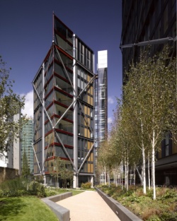
External perimeter bracing
NEO Bankside, London
(Video case study)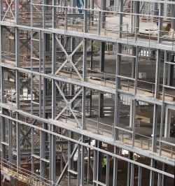
Typical bracing in a multi-storey braced frame


[top]Structural steel components
Main articles: Steel construction products, Modular construction, Composite construction

A wide range of steel components is available to the architect and designer including:
- Hot-rolled (open) sections, such as I, H and L shapes
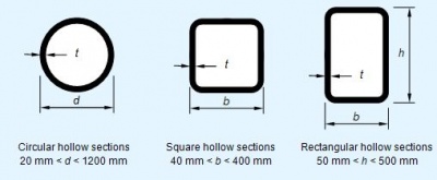
- Structural hollow (closed) sections of circular, square, rectangular and elliptical shape
- Fabricated sections made by welding together steel plates
- Cast steel components for repetitive uses, such as nodes
- Stainless steel components
- Light steel components made from thin strip steel
- Modular units made from light steel components.
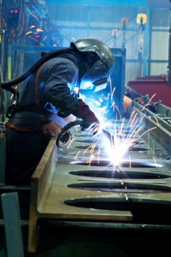
Site connections are usually made by bolting, while welding is preferred for factory-made connections.
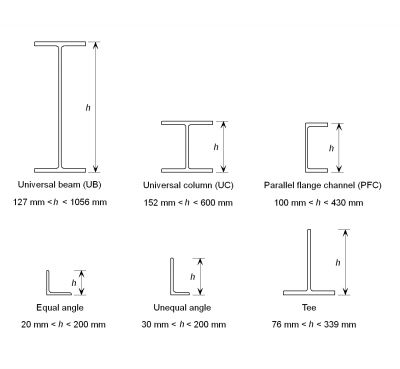
A wide range of standard hot-rolled steel sections is produced from which designers can select the profile, size and weight appropriate to a particular application. These are beam sections (UB), column sections (UC), parallel flange channels (PFC), structural hollow sections (SHS), and angle sections.

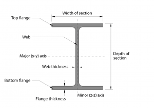

Modern open steel sections have parallel flanges. The serial size varies in increments of about 50 mm depth for the shallower sections, and about 75 mm for the deeper sections. The internal dimensions between the flanges are constant, whilst the flange thickness and overall dimensions vary with section weight. The standardisation of hot-rolled steel sections has led to the adoption of standard connections, which have become familiar within the industry.
The figure gives an explanation of terms used in connection with open hot-rolled sections. Detailed dimensions and sections properties of hot-rolled sections supplied by British Steel and Tata Steel are available here
[top]Steel beams

(Image courtesy of of Kloeckner Metals UK Westok)
Beams are designed to resist bending moments and shear forces. The shapes of hot rolled beam profiles are designed to achieve optimum bending properties for the use of steel. In the scheme design of uniformly loaded steel beams, sections with a span/depth ratio of 18 to 20 are typically used, i.e. for a span of 8 m, the steel beam will be approximately 450 mm deep. The table gives typical span-to-depth ratios for various types of beams used in different floor systems. Primary beams span between columns and secondary beams span between primary beams and support the floor slab directly.
| Form of construction | Span/depth ratios for different beam solutions | |
|---|---|---|
| Secondary beams | Primary beams | |
| Steel beam | 18-20 | 13-15 |
| Composite beam | 22-25 | 16-18 |
| Cellular beam+ | 20-27 | 15-18 |
| Shallow floor beam | 26-28 | - |
| Steel truss+ | 15-18 | 12-15 |
Note:
+Allows for the passage of services through the beam depth
[top]Composite beams
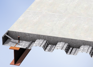

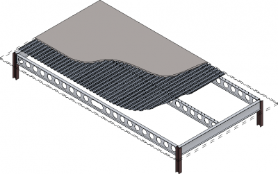
Steel beams can be designed to act compositely with a concrete slab by the use of shear connectors, normally in the form of welded steel studs that are site welded through the profiled steel sheet at regular spacing to the top flange of the steel beam. A composite edge beam with galvanised steel decking orientated parallel to the beam is shown.
Composite action greatly increases the strength and stiffness of a steel beam, and consequently can lead to longer spans for the same size of section or, alternatively, lighter, shallower sections may be used for the same load and span configuration. For the efficient design of composite beams, the ratio of span to beam depth is in the range 22 to 25, and so a composite beam is 25 to 30% shallower than a steel beam, and up to 30 to 40% lighter in steel weight.
Composite decking supports loads during construction without temporary propping up to approximately 4 m span, depending on the deck profile. Spans of up to about 5 m can be achieved, if the slab is propped during construction. An alternative form of composite beam is to use precast concrete slabs with a concrete topping.
[top]Structural systems in multi-storey buildings
Main articles: Multi-storey office buildings, Floor systems, Long-span beams, Trusses, Braced frames, Continuous frames, Composite construction
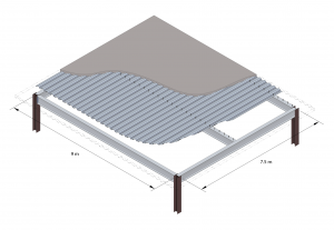

The layout of floor beams in buildings depends largely on the spacing of the columns. The columns along the perimeter of the building are generally spaced at 5 to 8 m in order to support the façade elements. In most buildings, the secondary beams are designed to span the longer distance in the floor grid, so that the bending moment they resist is similar to that of the primary beams and therefore they can be of the same depth as the primary beams.
The layout of beams in a 7.5 m x 9 m grid is shown in which the primary beams span the shorter grid distance, and are chosen to be the same depth as the secondary beams.
When shear connectors are to be welded through the steel decking, the top flange of the steel beams is not painted.
In buildings where headroom is limited, such as in renovation projects, UC sections may be used, instead of UB sections, as shallow, albeit heavier, beams.

In many buildings, designing longer internal spans creates more flexible space planning. A variety of structural steel systems may be used to provide either long-span primary beams or secondary beams. These long-span systems generally use the principles of composite construction to increase their stiffness and strength, and often provide for integration of services within their depth via openings in the webs of the beams.
Shallow floor construction differs from other forms of steel construction in not requiring secondary beams, other than tie members to connect the columns for robustness and for stability of the structure during construction.
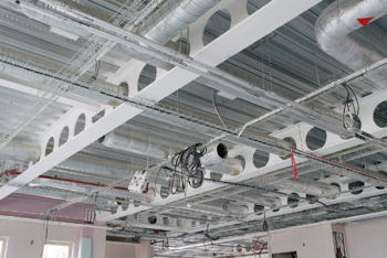
[top]Cellular beams
Castellated or cellular beams are examples of longer span members which have large, generally regular, openings within the web depth. These beams achieve the benefits of greater structural efficiency by increasing the section depth for a given use of steel, and provide multiple routes for services. Cellular beams have greater architectural appeal because of their apparent lightness and distinctive appearance in long-span roofs and floors.
In a castellated beam, the web of a rolled section is cut along the length of the beam in a hexagonal ‘wave’ form. The two pieces are separated, offset and then welded together to achieve a deeper section.
- Fabricating a cellular beam
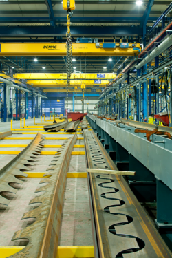
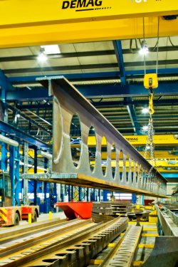


(Images courtesy of Kloeckner Metals UK Westok)

In a cellular beam, the web of a rolled section is cut to form circular or elongated openings. The diameter of the openings can vary between 0.5 to 0.8 times the depth of the beam. Cellular beams are structurally efficient and offer many architectural opportunities. When formed from rolled steel sections, the top and bottom parts of the cellular beam can be of different sizes, and the sections can be curved prior to the welding process. Very little waste is generated in this process and all steel offcuts are 100% recycled. An example of a floor system using cellular beams is shown right.
When beams are fabricated from three steel plates, the flange sizes may differ but the web is of constant thickness. The opening sizes can also be varied along the beams to suit the servicing requirements.
The most appropriate use of cellular beams is for long spans with moderate loadings, such as secondary beams in floor grillages or in roof structures. The regular circular openings in a cellular beam are very efficient for distribution of circular ducts in heavily serviced buildings. Elongated openings can be placed closer to mid-span (as shown) where the shear forces are low.

(Image courtesy of Kloeckner Westok)
[top]Beams with large web openings
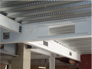

In composite beams, large openings may be formed through the web for the passage of services within the beam depth. Large openings are normally rectangular in shape, but more regular openings are generally circular. Welded stiffeners placed horizontally above and below the openings increase the size and aspect ratio of opening that may be used. For the scheme design of composite beams with various forms of openings, it is recommended that:
- Opening depths should generally be between 50 to 70% of the beam depth
- Circular openings may be placed at a spacing of half of their diameter (as for cellular beams).
- Large rectangular openings should be placed in the middle third of the span of the beam and should have a length-to-depth ratio of no more than 2, unless horizontal stiffeners are used.
- The spacing between the edges of rectangular openings, or to the connections of secondary beams, should not generally be less than the larger of the beam depth or opening length.
- For wide rectangular openings, horizontal stiffeners should be extended at least 150mm past the opening.
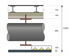

A cross-section through a perforated beam is shown. In this case, the opening depth is 400 mm and the beam depth of 600 mm is suitable for a span of up to 15 m. As shown, the overall floor depth allowing for a raised access floor and suspended ceiling is approximately 1.05 m.
[top]Shallow floor construction

Shallow floor systems use steel beams where the bottom flange is wider than the top flange. These may be proprietary rolled sections, USFBs or a flat steel plate welded to the bottom flange of a standard UC section. The wider bottom flange supports the floor slab so that the beam is partially encased within the floor depth, resulting in a structural system with no downstand beams, which leads to reduced floor-to-floor heights. The floor slab may be in the form of precast, hollow core concrete units or deep composite steel decking, in both cases supporting in-situ concrete that is placed level with or above the top flange of the beam.
Spans of the order of 6 to 9 m can be achieved in both directions. The overall floor depth is typically 300 to 350 mm, depending on requirements to control floor vibrations and provide fire resistance and acoustic insulation. The partial encasement of the steel beam in concrete means that, in general, 60 minutes fire resistance is provided, and 90 or 120 minutes fire resistance can be achieved by using additional reinforcement or by protecting the bottom steel plate.
The UC beam can be replaced by a Rectangular Hollow Section (RHS) when used as an edge beam because of its torsional stiffness and the neat edge it provides at the façade line. This may be visually desirable in some circumstances, such as in fully glazed facades. Also, cladding attachments may be made more easily to the RHS section than to a concrete slab or an encased steel-section.
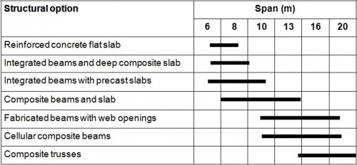
[top]Summary of spans of the structural options
Typical spans and structural depths of different steel and concrete structural options are shown in the tables. The overall floor depth includes the services and ceiling zone, and, if necessary, a raised access floor. For the long span systems, services are generally incorporated within the structural depth, i.e. with web openings in the beams. An overall structural and services depth of 1 to 1.2m (including 120mm for the ceiling) is generally used in planning for multi-storey buildings, depending on the span.

| Structural option | Structural depth (floor to ceiling) (mm) |
|---|---|
| Composite beam construction | 800 – 1,200 |
| Cellular beams (with service integration) | 800 – 1,100 |
| Downstand beams with precast concrete floor slabs | 1,200 – 1,450 |
| Shallow floor or integrated beams | 600 – 800 |
For offices and many other building types, 3m is used as the floor to ceiling depth, in which case, the floor-to-floor zone is 4 to 4.2m. For some types of building, a 2.7m internal height is acceptable in which case, the overall floor zone is 3.6 to 4m.
| Project type | Typical floor-to-floor+ height (mm) |
|---|---|
| Prestige office | 4.0 – 4.2m |
| Speculative office | 3.6 – 4.0m |
| Renovation project | 3.5 – 3.9m |
Note:
+Floor-to-ceiling height plus the floor depth including services
[top]Columns
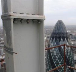

Columns in braced frames are generally in the form of UC sections that are spliced (joined) longitudinally at appropriate points, usually every two or three storeys in tall buildings. Beam-to-column connections are made either to the flanges of the column (major axis connections) or to the web of the column (minor axis connections). It may also be necessary to stiffen the columns locally at points of load transfer, such as for beams with moment connections. For 3 to 5 storey buildings, a 254 x 254 UC column is commonly used and for 6 to 8 storey buildings, a 305 x 305 UC.
Square or Circular Hollow Sections are very efficient in compression because of their increased resistance to buckling in both axes compared to open sections. Both circular (CHS) sections and square (SHS) sections are widely used as slender columns. The main design issue is the connection to the face of the column, which is often in the form of welded fin plate with bolts to the beam web. End plate connections may be used with expanding anchors or proprietary 'blind' fixings.
Columns may be designed to achieve greater compression and fire resistance by concrete encasement (in the case of H sections) and concrete filling (in the case of hollow sections). For example, the in-filling between the flanges of an H section column without reinforcement can increase its fire resistance up to 60 minutes whilst retaining the same external dimensions of the section. The in-filling of hollow sections with concrete can increase their fire resistance to up to 60 minutes without reinforcement, and up to 120 minutes with reinforcement.
In structures such as portal frames, where bending moments are the dominant form of loading, UB sections are generally used for the columns.
[top]Trusses and lattice girders

Trusses and lattice girders are used in long span roofing and flooring systems. The term ‘truss’ is generally applied to roofs, which may be pitched, whereas lattice girders are generally used as long-span floor beams which are more heavily loaded and not pitched.
Trusses and lattice girders are often designed to be visible and therefore the choice of the members used and their connections is important to the design solution.
Trusses and lattice girders are triangular or rectangular assemblies of tension and compression elements. The word ‘lattice’ refers to the use of N-type or W-type bracing along the member. The top and bottom chords provide the compression and tension resistance to overall bending, and the inclined bracing elements resist the shear forces.
A wide variety of roof trusses can be created. Each can vary in overall geometry and in the choice of the individual elements within them. Trusses may be designed to follow the roof profile, which may also be curved, whereas lattice girders are used as long spanning beams. Trusses or lattice girders may take a number of basic forms and they are fabricated by bolting or welding standard sections together. For spans of up to 20 m, it is sufficient to use angles, tees and lighter hollow sections. For very long spans, UC or heavier hollow sections may be required. The bracing members are usually lighter than the chord members.

The bracing (diagonal) members are usually arranged in a W or N form. In the N form, the orientation of the bracing members normally changes at mid-span, as illustrated below. In the W form, the members are often fabricated from tubular sections as they are efficient as bracing members, which act alternately in tension and compression. In lightweight buildings, wind uplift can be significant and may cause reversal of the forces acting on the truss.
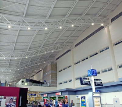
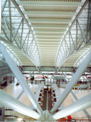
Triangulated trusses are often used in long span structures as they are very stable due to their shape. The normal form is for the triangle to point downwards so that the secondary beams span between the top chords. A good example of a curved triangular truss at Hamburg airport is shown. These trusses were supported on inclined tubular arms.
[top]Space frames
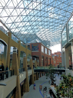

A ‘space’ frame is a form of construction that covers large areas using assemblies of small structural components that are connected at pre-formed nodes. They are three-dimensional assemblies that generally consist of tension and compression elements, connected by inclined bracing. Circular hollow sections (CHS) are generally used in space frames as their wall thickness can be varied to suit the forces in the members while maintaining a constant outside diameter. There are three generic forms of support to space frames that determine the forces to which they are subject:
- Point support by columns at four or more positions
- Multiple supports by rows of columns or ‘column trees’.
- Continuous edge support.
An example of the multiple point supports to a double layer space frame over a pedestrian street in Belfast’s Victoria Centre is shown.
[top]Forms of bracing in braced frames

(Image courtesy of William Haley Engineering Ltd.)
Pin-jointed structural frames have to be braced in the vertical and horizontal directions. The stability of the building is dependent on the form and location of the bracing. Other lateral force-resisting elements, such as concrete cores, can be linked by floors or horizontal bracing. For simplicity, vertical bracing is often located in the façade or internal separating walls. Ideally, the bracing line would be on the centre-line of the main columns, but this may conflict with the location of the inner skin of external walls and so it may be necessary to integrate the bracing and wall construction without causing thermal bridging.
The most common arrangements of bracing in multi-storey construction is ‘X’, ‘V’ or ‘K’ bracing using steel angle or circular hollow sections. Inverted ‘V’ bracing is preferred where substantial openings, e.g. doors, are required in the braced bay.

In the X braced form, the members are usually designed to resist tension only, which leads to more slender members. Tension rods or flat plates are ineffective in compression, and, therefore, forces are resisted only in tension when using these elements. An example of X bracing using tie rods connected to a circular ring is shown. This type of detail is often used in both visually exposed and concealed bracing but the tension that can be developed in the tie is limited by bending of the connecting ring.

In the K and V-braced forms, the members must be designed to resist tension and compression. Tension ties are not possible in this case. In X braced frames using circular or square hollow sections (SHS), the members may also be designed to resist compression, and splice details allow connection of the four tie members at the cross-over points. An example of exposed X bracing using SHS sections is shown. The shear forces that this system can resist are also dependent on the shear resistance of the bolts at the splice.
Flat steel plates may be used when they are required to fit in the cavity of brickwork or in double layer separating walls. Normally flat plates are used in X bracing, designed to act only in tension.
[top]Structural systems in single storey buildings
Main articles: Single storey industrial buildings, Portal frames, Moment resisting connections

The most economical way to enclose a large space is to use a series of two-dimensional ‘rigid’ frames that are spaced at equal intervals along one axis of the building. For single-storey buildings, stability is achieved in the two directions either by the use of rigid framing, bracing, or through the supporting action of concrete walls or cores. Rigid framing can be achieved in one direction by the use of moment-resisting connections but is rarely used in the other direction which is therefore braced conventionally.
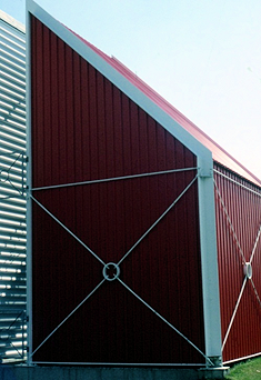
[top]Exposing the frame
The steel frame may be exposed internally but may also extend outside the façade or roof to form an external structure. The structural form may be expressed by locating the steel frame entirely outside the cladding, or located wholly internal to the building envelope. Between these two extremes, the interaction of the frame and cladding establishes a further range of visual and spatial relationships.
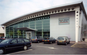

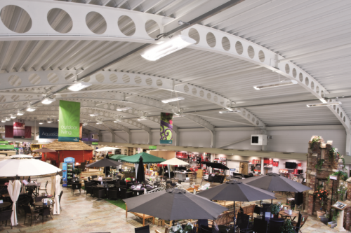
A simple example of a framed structure that is continued outside the building envelope to provide a visual effect is shown. In this case, the perforated cellular beams enhance the lightness of the structure whilst preserving its primary function as a rigid frame.
Where the steel structure penetrates the building envelope, care should be taken to minimise heat loss via thermal bridging.
[top]Portal frame structures

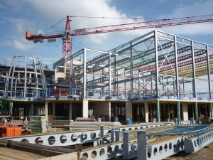
(Image courtesy of Severfield (Design & Build) Ltd.)
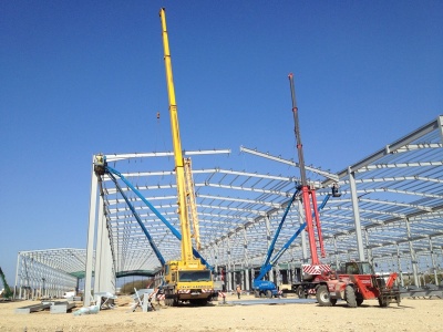
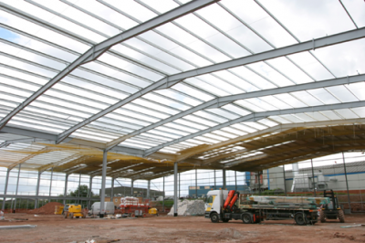
Portal frame structures are examples of rigid frames, and are the most common form of enclosure for spans of 20 to 50m. Portal frames are generally fabricated from hot-rolled open sections, although they may be formed from lattice or fabricated girders. They are braced conventionally in the orthogonal direction in the side walls and, if permitted, between internal columns.
In general, portal frame structures are used in single-storey, industrial type buildings or enclosures where the main requirement is to provide a large enclosed volume such as a sports hall or distribution centre. As such, these structures may not be of architectural significance. However, the basic principles can be used in a number of more interesting architectural applications, for example, by forming curved rafters or by using perforated beams.
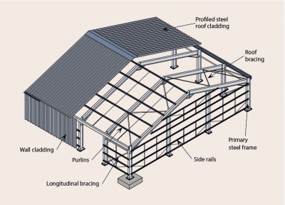
The frame members normally comprise rafters and columns with rigid connections between them. Tapered haunches are introduced to strengthen the rafters at the eaves and to form moment-resisting connections. Roof and wall bracing is essential for the overall stability of the structure. The elements of a portal frame are shown in the figure.
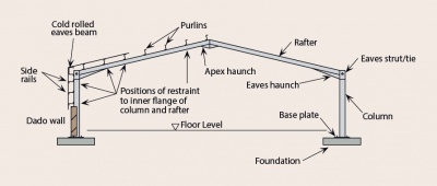

The table presents some general guidelines for the design of portal frame structures. The minimum roof slope, allowing for deflections, is normally taken as 6°. The columns are generally 50% heavier than the rafters and the column height may vary from approximately one-fifth to two-thirds of the frame span. The spacing of the frames depends on the spanning capabilities of the purlins and the snow loading.
| Parameter | Typical value |
|---|---|
| Span of portal frame | 15 to 50m |
| Spacing of frames | 5 to 8m |
| Roof slope | 5° to 10° |
| Rafter depth | Span/50 to Span/60 |
| Ratio of span to column height | 4 to 7 |
| Column weight (kg/m) | 1.5 to 2 × Rafter weight (kg/m) |
| Haunch length | 10% of span |
| Haunch depth | 2 × Rafter depth |
| Spacing of purlins | 1.5 to 2m+ |
Notes:
- No cranes or heavy additional loads
- +Purlin spacing reduced close to the haunch to provide stability to the haunch

Two-bay portals are often designed as ‘hit and miss’ construction in which alternate internal columns are replaced by a longitudinal spine beam that spans between the ‘hit’ columns and supports the point load from the missing column.
A mansard roof shape can be created from linear members using welding or bolting. This approach can be used for curved roofs by faceting shorter linear sections of the rafter and varying the height of the purlin supports to form a curved external profile.

Curved beams may be used instead of inclined rafters. The radius of the curve is normally such that the cladding can be installed to the roof curvature. However, some cladding systems, such as deep composite panels, may be less appropriate for roofs with significant curvature.
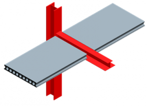
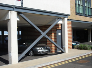
The image shows an interesting architectural solution where a pinned beam to column connection in a portal frame is made moment-resisting by the use of an external tie member to the column. In this way, the tie transfers a moment to the column.
[top]Further reading
- Steel Designers' Manual 7th Edition. Editors B Davison & G W Owens. The Steel Construction Institute 2012
- Architectural Design in Steel – Trebilcock P and Lawson R M published by Spon, 2004
[top]Resources
- SCI P167 Architectural Teaching Resource Studio Guide, 2000
- Best Practice in Steel Construction: Commercial Buildings
- Steel Buildings in Europe - Multi-storey buildings:
- EP37 Best Practice in Steel Construction – Industrial Buildings, Guidance for architects, designers & constructors
- Steel Buildings in Europe - Single storey buildings:
[top]See Also
- Visually expressed structural forms
- Use of steel in cladding systems
- Steel construction products
- Multi-storey office buildings
- Braced frames
- Continuous frames
- Simple connections
- Floor systems
- Long-span beams
- Trusses
- Composite construction
- Service integration
- Single storey industrial buildings
- Portal frames
- Moment resisting connections