


Floor vibrations
In recent years, there has been an increase in demand for buildings that are fast to construct, have large uninterrupted floor areas and are flexible in their intended final use. Modern design and construction techniques enable steel construction to satisfy these demands and deliver structures which are competitive in terms of overall cost.
For most multi-storey commercial buildings, straightforward steel construction will meet the required vibration performance criteria without modification. For more vibration-sensitive applications, such as hospital operating theatre floors, steel’s advantages can be utilised, although stiffer solutions may be necessary. Even if a stiffer floor is required, steel remains the most cost-effective and lightweight solution.
Long-span applications, for which steel is the only option, have been found to offer very good vibration damping, despite common preconceptions that damping in composite floors is lower than that of concrete structures. This is because of the large mass of the long-span sections which participate in any motion reduces the magnitude of the vibration response. The steel sector has extensive experience in designing steel structures to ensure compliance with even the strictest vibration performance criteria.
The subject of floor vibrations is complex. This article describes the basic theory of floor vibrations, human perception and acceptability levels and provides practical methods for assessing the likely vibrational behaviour of floors in steel framed buildings.


[top]Introduction to floor vibrations
[top]Vibrations
The term ‘vibrations’ when applied to floors refers to the oscillatory motion experienced by the building and its occupants during the course of normal day-to-day activities. This motion is normally vertical (up and down), but horizontal vibrations are also possible. In either case, the consequences of vibrations range from being a nuisance to the building users to causing damage to the fixtures and fittings or even (in very extreme cases) to the building structure. The severity of the consequences will depend on the source of the motion, its duration and the design and layout of the building.
Sensitive process/equipment such as nano-technologies, microscopes or lasers may be sensitive to a level of vibration which is often below human perception. In such special cases, malfunctioning of the equipment is avoided by limiting the level of vibration to the specific requirement of the equipment.
Severe vibration events due to earthquakes and explosions are outside the scope of this article.
Once constructed, it is very difficult to modify an existing floor to reduce its susceptibility to vibration, as only major changes to the mass, stiffness or damping of the floor system will produce any perceptible reduction in vibration amplitudes. It is important therefore that the levels of acceptable vibration be established at the concept design stage, paying particular attention to the anticipated usage of the floors. The client must be involved in this decision, as the specified acceptance criteria may have a significant impact on the design of the floor and the cost of construction.
[top]Sources of vibration
Floor vibrations are generally caused by dynamic loads applied either directly to the floor by people or machinery or indirectly by moving floor supports after transmission through the building structure or through the ground. The principal sources of vibration in buildings are:

- Human activity, e.g. walking, dancing, jumping, etc.
- Vibrating machinery
- External forces, e.g. traffic at ground level or underground, or wind buffeting.
The most common source of vibration that can cause nuisance in building applications is human activity, usually walking. Although small in magnitude, walking-induced vibrations can cause a nuisance to people working or living in the building, especially to the use of sensitive equipment or to those engaged in motion-sensitive activities, e.g. surgery. Naturally, the problem is more acute for more vigorous types of human activity such as dancing and jumping and therefore designers of buildings featuring a gymnasium or dance studio should take extra care to limit the vibrations in the rest of the building.
Machinery-induced vibrations are best dealt with at source through the provision of isolating mounts or motion arresting pads. Machines installed in factories tend to produce the most severe vibrations due to their size and the nature of their operation. However, floor vibration is rarely a problem in most factories, since it is accepted by the workforce as part of the industrial environment.
Wind induced vibrations are generally not an issue for normal building construction, such as low to medium rise commercial or residential buildings. Where they need to be considered, building designers should consult the appropriate wind loading code of practice, e.g. BS EN 1991-1-4[1] in the UK.
Ground-borne vibrations can be problematic, but are best dealt with at source, e.g. repairing the pot-hole in the road. However, where problems are anticipated, such as when a building is adjacent to a busy road, steps should be taken to minimise the transmission into and through the building structure. Careful detailing of the structure and foundations plays a key role in this respect.
[top]Consequences of vibrations
For the building designer, there are three principal effects of floor vibrations that may need to be considered, depending on the frequency of occurrence and the magnitude of the vibration. These are:
- Nuisance – Human occupants of a building can perceive very low amplitudes of vibration and, depending on the circumstances, even modest doses of floor vibration can cause discomfort or alarm. Certain items of precision equipment are also extremely sensitive to vibration.
- Strength – The structure must be strong enough to resist the peak dynamic forces acting on it. Depending on the relative frequencies of the applied force and the building structure, together with the duration of dynamic event, the dynamic response can be significantly greater than the response due to equivalent static load. In such cases, it will be necessary to design the structural members and their connections to resist these higher loads.
- Fatigue – Fatigue cracks can initiate and propagate when a structural component, usually a connection, is subjected to repeated cyclic loading, such as in bridges. For steel, there is a limiting stress below which fatigue will not occur irrespective of the number of cycles. Fatigue may therefore be avoided by designing connections such that this stress limit is not exceeded.
Of these three potential consequences, nuisance caused by the perception of vibrations is the most common issue for most building applications. It is, therefore, the focus of this article. Strength and fatigue issues are sometimes encountered in buildings used for rhythmic activities such as gymnasia, dance studios and nightclubs.
[top]Theory of vibrations
Vibrations are characterised by a regular cyclic motion of a given frequency and amplitude. In practice, vibrating floors are complex dynamic systems with infinite modes of vibration, each with its own frequency. Fortunately, even the most complex vibrating system may be represented as a series of simple mass and spring models with a single degree of freedom. Such models are easy to understand in terms of their theoretical behaviour and are a useful means of introducing the fundamental principles that govern the motion of all vibrating systems.
[top]Single degree of freedom systems
The simplest vibrating system is one with only a single degree of freedom (SDOF), such as the mass and spring model shown below.
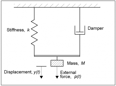

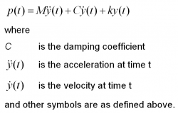
In this system, if the mass M were displaced from its equilibrium (rest) position and then released, its displacement y plotted against time t would represent a sine wave. In the absence of damping, this motion would continue indefinitely, with the peak displacement corresponding to the initial release position. The time taken to complete each cycle would depend only on mass M and spring stiffness k of the system. In practice, all vibrating systems encounter a degree of damping. This is represented in the SDOF model by the dashpot damper. As an alternative to displacing and then releasing the mass, the vibrations could be initiated by subjecting the mass to a dynamic (time varying) load. This is represented in the model by the external force p(t). The motion of the SDOF system can be defined in terms of three parameters:
- Frequency
- Amplitude
- Damping.
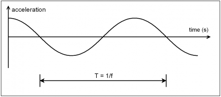
The frequency of a system, or of an applied force, is a measure of the rate at which the system vibrates. The frequency is normally quoted in Hertz (cycles per second) or alternatively in radians per second and is proportional to the square root of the stiffness k divided by the mass M. The inverse of the frequency f is the period T, defined as the time taken for the system to complete one whole cycle.

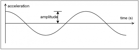
The amplitude of a system is a measure of the peak response relative to the mean. Since the motion is sinusoidal in nature, the term amplitude applies equally to the displacement, velocity or acceleration. In the case of floor vibrations, the amplitude usually refers to the peak acceleration, since acceleration is generally used to determine the acceptability of the floor.

Damping refers to the loss of mechanical energy in a system. There are many sources of damping in a building, including friction at the connections, furniture and fit-out and energy dissipations through non-structural components such as partitions. As energy is taken out of the system through the damping, the amplitude of the response reduces until the motion eventually ceases. The amount of damping will determine the duration of the response and can be critical in situations involving resonance.

For the SDOF system shown above, subjected to a load p(t), the motion of the system is governed by dynamic equilibrium, which may be expressed as:

[top]Continuous systems
A beam may be thought of as a series of mass/spring models joined together to form a continuous system. Unlike the SDOF system, which has a single natural frequency and corresponding mode of vibration, a continuous system theoretically has an infinite number of natural frequencies and associated modes. When the beam vibrates, these modes are superimposed on one another to give the overall response of the system. Fortunately it is generally sufficient to consider only the first 3 or 4 modes, since the higher modes are quickly extinguished by damping.
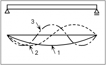
The different responses of a system may be represented by ‘mode shapes’, which show the deflections of the deformed shapes of the system. The fundamental (or first mode) frequency always corresponds to the mode shape with the lowest frequency. The first three mode shapes of a uniform simply supported beam are shown in the figure.

For design purposes, the fundamental frequency of a simply supported beam may be estimated using the following expression:
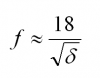

where δ is the deflection due to the self weight and any other loads that may be considered to be permanent. To complicate matters further, real structures comprise a framework of beams, connected together directly or via columns. This results in vibration modes involving several beams moving simultaneously, together with an area of floor slab. In this case, the fundamental frequency of the system will depend on the motion of the primary and secondary beams and concrete slab. The fundamental frequency of the whole system will be lower than those of the individual components and may be obtained using:

where δmax is the total deflection of the primary beam, secondary beam and slab expressed in millimetres. Alternatively, the fundamental frequency of the floor system may be obtained using Dunkerly’s approximation as follows:

where fs, fb and fp are the fundamental frequencies of the slab, secondary beam and primary beam respectively.
[top]Types of response
The response of a floor may be classed as either:
[top]Resonant response
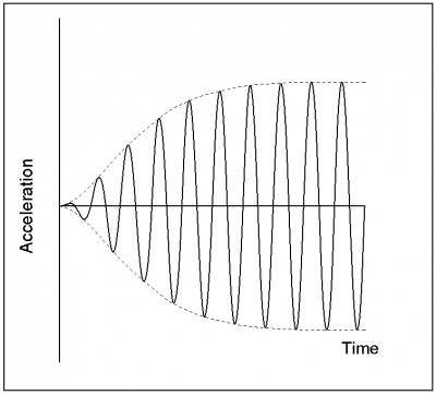

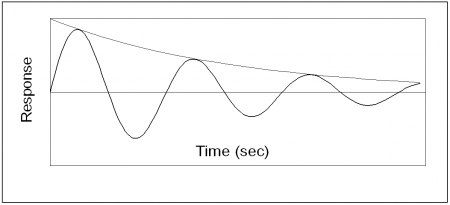
When a continuous (sinusoidal or cosinusoidal) force is applied to a system with the same frequency as that of the system, each successive load cycle will add to the response, causing the amplitude to increase. In the absence of damping, the amplitude will increase to a magnitude well in excess of the level of acceleration resulting from a single load cycle. This is known as resonance and, if allowed to develop in a structure, can result in unacceptably high responses and damage to the structure. Fortunately, in building structures, the energy in the vibrating system is dissipated by damping over a number of cycles and resonance does not occur. Instead, the response settles down to a steady state having a constant amplitude. In this state, each new cycle of load merely replenishes the energy lost to damping. The build-up to a typical steady state response is shown.
It should be noted that, despite damping, the steady state amplitude is several times the initial amplitude, and this response may still be problematic to the building designer. Increasing the level of damping will reduce the steady state resonant response.
In addition to the level of damping, the amplitude of the response also depends on the amount of mass that is mobilised, the magnitude of the applied force and the ratio of the forcing frequency to the natural frequency of the system. On this last point, it is important to remember that floors possess many (in theory infinitely many) natural frequencies, corresponding to the different modes of vibration. To avoid resonance, it is also important to ensure that the frequency of the applied force does not match the frequency of the first few vibration modes of the floor.
[top]Response to periodic impulses
If the natural frequency of the structure is significantly higher than the frequency of impulses, during each cycle of periodic impulsive loading there will be several cycles of response. Damping in the system will reduce the amplitude of the response, until the arrival of the next cycle of load. The resulting impulsive response is shown.
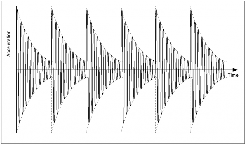

In this case, the peak amplitude corresponds to the arrival of each successive load and, therefore, is independent of the degree of damping. The magnitude of the response is dependent only on the magnitude of the impulsive force and the amount of mass that is mobilised.
[top]Human induced vibration

The simple act of walking across a floor might not seem to be too onerous to the building designer, especially when the structure has been designed for a much higher level of load. However, in environments such as hospitals or quiet offices, a single person walking along a corridor can be a serious nuisance to other building occupants.
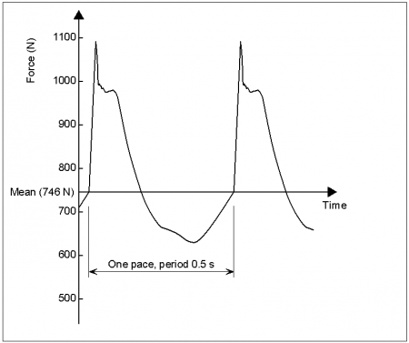
A person walking at a regular pace applies a periodically repeated forcing function to the floor at a frequency of between 1.6 to 2.2Hz. This may cause a build-up of response, i.e. resonance. Although dominated by the pacing frequency, the periodic loading caused by walking is made up of several frequencies superimposed on one another. When considering the possibility of resonance, account must be taken of these higher excitation frequencies. A typical force-time plot for walking is shown.
To establish the overall response, this forcing function can be broken down into a series of sine waves, each of which has a frequency at an integer multiple (or harmonic) of the forcing frequency. Each harmonic will have an associated amplitude and phase shift, and the set of harmonics are known as a Fourier series.
Although not immediately apparent from the image provided, the cyclic loading due to walking may be broken down into a series of sine waves, each representing one of the constituent frequencies. Each component of the response may be weighted by the appropriate factors (Fourier coefficient) and then summed to give a good approximation to the actual loading. In the case shown, the pacing frequency is 2 Hz, with higher harmonic frequencies of 4 Hz, and 8 Hz. The lowest frequency will always be the most significant and resonance at this frequency should always be avoided (by ensuring that the natural frequency of the floor is sufficiently high). A similar treatment can also be applied to other human activities such as running, jumping and dancing.
Recommended design frequencies and Fourier coefficients for common activities may be found in the relevant Regulations and design rules.
[top]Acceptability of vibrations
Generally, the vibration of floors is considered to be a serviceability issue, primarily related to the discomfort of building occupants or damage to sensitive equipment. Where there is sensitive equipment, it is a relatively straightforward matter to specify the maximum permissible acceleration. However, discomfort to humans cannot be directly quantified, since perception and tolerance vary between individuals and are highly dependent on the circumstances.
[top]The human perception of vibration
The following factors are known to influence the human perception of vibration:
- Type of activity
- Time of day when the activity is being undertaken
- The type of environment where the activity is taking place
- The direction of the vibration
- The amplitude of the vibration
- The frequency of the vibration
- The source of the vibration
- The level of damping
- The duration of the exposure.
[top]Design criteria for vibrations
The subjective nature of vibrations means that it is not possible to prescribe an exact limit that will guarantee an acceptable floor response. Instead, the design guidance aims to ensure that the building will attract ‘a low probability’ of adverse comment from its occupants.
Historically, designers have used the natural frequency of the floor as the sole measure of acceptable performance. By specifying a sufficiently high natural frequency, the intention was that the floor would be effectively ‘tuned’ out of the frequency range of the walking activity. However, while this might be true for the first harmonic, resonance could still occur on the second, third and fourth harmonics of the walking activity.
Current Standards quantify the magnitude of floor vibrations in terms of the acceleration of the floor; defined in terms of weighted, root-mean square (rms) acceleration. The acceptability of a floor is assessed by dividing the predicted acceleration by a baseline value to obtain a response factor, and checking that the calculated response factor is less than the appropriate multiplying factor given in the relevant Codes and other specialist guidance.
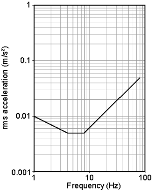
The baseline acceleration is dependent on the direction of the vibrations relative to the human body (the z-axis is defined as head-to-toe, whether the person is standing or lying) and the frequency of the vibration.

The baseline acceleration for the z-axis, as specified in BS 6472[2], is shown below. The line represents a constant level of human perception. The area above the line corresponds to an increasing level of human perception to vibration; the area below the line represents vibration that is imperceptible to the majority of humans.

The response factor is compared against the specified maximum allowable response factor for the application. The allowable response factor should take account of the human perception factors listed above and may be obtained from Standards, published guidance or may be specified by the client. Specialist guidance is available for hospitals.
The response factor approach assumes continuous vibration over a 16 hour day or 8 hour night. If the vibrations are only intermittent in nature, the building designer may take advantage of the reduced duration by using the Vibration Dose Value (VDV) approach. This alternative method may prove especially beneficial in buildings where the vibration is caused by discrete and infrequent events, rather than continuous activity, for example residents of an apartment block leaving for work in the morning and returning several hours later.
[top]Design for rhythmic activity
Where floors are likely to be subject to dancing and jumping activities characterised by synchronised crowd movement, the floor must be designed for ultimate limit state considerations in accordance with the requirements given in the National Annex to BS EN 1991-1-1[4].
According to these Standards:
- The floor may be designed to have a fundamental frequency of at least 8.4 Hz vertically and at least 4 Hz horizontally, in which case the resonant effects need not be evaluated.
or
- The floor should be designed to resist the anticipated dynamic loads due to rhythmic activity which should be considered as an additional imposed load case.
The vertical natural frequency of the floor should be evaluated for the appropriate mode of vibration for an empty structure.
[top]Designing for dynamic loads
As noted above, a dynamic load may result in considerably higher forces and moments in a structure compared to the corresponding static load. The degree of magnification depends on the ratio of the frequency of the loading function (fp) to the natural frequency of the structure (fn); the level of damping present in the structure is also important.
The ratio of dynamic to static responses is known as the Dynamic Magnification Factor (DMF). The relationship between DMF (fp/fn) and damping ratio is shown below.


It is apparent from the figure that, as the frequency of the applied load approaches the natural frequency of the structure (fp/fn =1), resonance occurs leading to very large DMF values. The magnitude of the DMF at resonance is dependent on the degree of damping. Theoretically for undamped systems, i.e. ξ = 0, the steady-state response tends towards infinity. Since in many practical structural systems the critical damping ratio is of the order of 1%, the dynamic magnification can be considerable, if precautions are not taken to avoid resonance.
Resonance on the fundamental frequency (the worst case) may be avoided by designing the floor to have a natural frequency of over 3Hz. This ensures that the fundamental frequency of the floor will be higher than the lowest harmonic of walking.
[top]Vibration analysis
[top]Basic principles
The vibration characteristics of a structure are defined by its modal properties comprising:
- Natural frequency
- Modal mass
- Mode shape
- Modal damping.
For any structure, there are an infinite number of modes, each with its own set of properties. However, in practice, only those modes with the lowest frequencies will be relevant to the analysis.
For each individual mode, the natural frequency is the number of oscillations per second, the mode shape is the deformed shape that the structure would naturally tend to exhibit at that frequency, and the modal damping defines the energy dissipation within the mode. The first three modal properties are dependent on the dimensions, mass and stiffness of the structure and may be calculated using one of the methods described below. Damping depends on the finishes on the structure and an appropriate value will generally have to be assumed (based on past experience or testing).
As real structures are built up from a number of components, the determination of the modal properties is a complex process, requiring consideration not only of all of the members within the structure, but also the interaction between these members. The most effective way of assessing the modal parameters of a structure is by finite element analysis, but simplified methods may also be used on some simpler structures. Simplified methods are usually only applicable to regular structures with rectilinear grids and may be conservative.
[top]Finite element modelling
Finite element modelling may be used to obtain the natural frequencies, modal masses and mode shapes of any shape of floor, but the method is particularly useful for buildings with irregular grids or onerous design requirements with regard to vibration e.g. hospitals. The method is more accurate and generally less conservative than hand calculation methods.
Finite element modelling is an approximation, in which a continuous structure is divided into a number of parts or elements. The accuracy of the solution is dependent on the number of elements into which the system is divided, but this has to be balanced against the longer computation time. Selecting the optimum number of elements is crucial to the success of the analysis. There are no firm rules for determining the mesh size (and hence number of the elements) but in general, if the number of elements can be doubled without significantly changing the result, then the number of elements is sufficient.
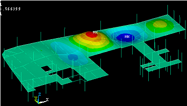

A typical output from a modal finite element analysis of a building is shown. The figure shows the plot of one of the floor’s many mode shapes superimposed on an outline of the floor. The red and blue areas indicate positive and negative modeshape amplitudes respectively (to an exaggerated vertical scale). For a given floor, the software will generate as many of these plots or modeshapes as required, together with the corresponding natural frequency and modal mass. In practice, it is generally sufficient to consider only the first 30 modes, i.e. the mode shapes corresponding to the lowest 30 natural frequencies.
Having obtained the mode shapes, frequencies and modal masses, the vibration response of the floor to a given excitation, e.g. a person walking at a known pace along a corridor may be obtained by modal superposition. As the name suggests, this is a process whereby the responses (accelerations) from each of the individual modes are superimposed on one another and summed to obtain the total response. This is best achieved with the aid of software.
For the majority of buildings, the walking paths are not known at the time of analysis, so the response is calculated on the basis that the response and excitation points are coincident, i.e. the acceleration is calculated at various points around the building assuming that the person causing the acceleration and the person feeling it are standing at the same location. This is likely to produce the worst case response at each location. A range of realistic walking frequencies is considered to obtain the highest response.
The end product of the analysis will be a matrix of accelerations, corresponding to the nodes of the finite element mesh. It is normal practice to divide these accelerations by the baseline acceptable value to obtain a series of response factors. These may be superimposed on the floor plan in order to visually identify any potential problem areas.
[top]Simplified assessment of floors with steel beams
To avoid the need for a finite element analysis, a simplified assessment method has been developed for simple building layouts comprising regular grids of steel beams supporting a concrete floor slab. It is also suitable for composite floors. This design procedure is based on a parametric study of a wide variety of floor grids modelled using finite element analysis. The method is described in detail in SCI P354 and is summarised in the flowchart below.
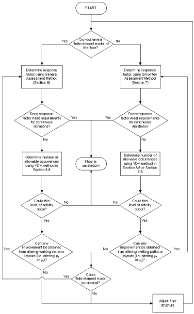

Note: Section numbers refer to those in SCI P354
The design procedure comprises the following steps:


- Calculation of natural frequency
- Determination of modal mass
- Evaluation of the critical acceleration and hence response factor
- Checking the response factor against the acceptance criteria (for continuous vibration).
In conventional steel-concrete floor systems, the fundamental frequency may be estimated by using engineering judgement on the likely deflected shape of the floor (the mode shape), and considering how the supports and boundary conditions will affect the behaviour of the individual structural components. For example, on a simple composite floor comprising a slab continuous over a number of secondary beams that are, in turn, supported by stiff primary beams, two possible mode shapes may be sensibly considered, as shown below:
- Secondary beam mode
- Primary beam mode.
In the secondary beam mode, the primary beams form nodal lines, i.e. they have zero deflection, about which the secondary beams vibrate as simply-supported members. The slab is assumed to be continuous over the secondary beams. In the primary beam mode, the primary beams vibrate about the columns as simply-supported members and the secondary beams and slab are taken to be fixed-ended.
The natural frequency should be calculated for each mode, allowing for the deflection of both sets of beams and the slab, and the fundamental frequency of the floor should be taken as the lower value of the two modes considered. The modal mass for the critical mode may be obtained from the simplified equations in SCI P354. The acceleration may then be obtained by treating the floor as an equivalent single degree of freedom system.
[top]Floor response calculator
A web-based Floor response calculator is also available that allows designers to make an immediate assessment of the dynamic response of a floor solution. The software reports the results of approximately 19,000 arrangements of floor grid, loading and bay size, which have been investigated using finite element analysis. The results from this software provide an improved prediction of the dynamic response compared to the ‘manual method’ in SCI P354, described above. The software may be used to examine complete floor plans or part floor plans, comparing alternative beam arrangements.
[top]Dynamic testing of floors
Testing and vibration performance assessment based on experimental data are powerful tools which can be used to ascertain the as-built vibration behaviour of building floors. This is particularly true for complex floor layouts or in situations where the floor vibration performance is critical for day to day operation of a building, such as in hospitals. Due to the uncertainties associated with the two analytical methods described above (frequency method and response factor method), clients often ask for in-situ testing of floors after they are constructed to check the actual performance and verify the accuracy of the design calculations.
There are two principal categories of dynamic floor test, relating to the purpose and desired output of the test:
- Measurement of the modal properties of the floor
- Measurement of the response of the floor to dynamic loading.
[top]Modal testing
The purpose of modal testing is to establish experimentally the modal properties of the structure. There are two types of modal test. Those where:
- The excitation force creating the response is not measured
- The excitation force creating the response is measured.
[top]Modal testing without measuring the excitation force
There are three types of test in common use:
- Ambient vibration survey (AVS),
- Heel-drop excitation
- Rotating mass shaker excitation.
In the ambient vibration survey the floor dynamic excitation is provided by the environment in which it resides. Vibration responses to this kind of excitation are acquired over a grid of test points covering the floor area of interest. This grid needs to be dense enough to describe all of the likely floor mode shapes in sufficient detail. It is also necessary to ensure that the modes of interest are excited by the ambient environment and that the reference transducers are away from the nodal points of the mode being measured.
Excitation in a heel-drop test is provided by a single person raising himself on the balls of the feet, and dropping onto the heels, thus providing an impact. The multi-modal decaying response to this impulsive broadband excitation can be measured at one or more locations simultaneously. This method may be used to obtain the modal frequencies of the floor.
In the rotating mass exciter, two masses rotate in a vertical plane at the same speed but in opposite directions, so that the horizontal components of their inertial forces cancel, leaving only a sinusoidally varying vertical force. Harmonic forces at particular frequencies generated by the rotating mass shaker excite floor harmonic responses at the same frequencies. These are then measured simultaneously at one or more grid points on the floor and their amplitudes recorded. The excitation frequency is then changed and the corresponding harmonic response amplitudes are again recorded. By repeating this process for a number of frequencies and plotting the recorded amplitudes against the frequencies for each test point, it is possible to estimate likely natural frequencies of the floor.
A common feature in all these modal testing methods, where the excitation force is not measured, is that modal properties tend to be less reliable than those obtained from tests where the excitation force is measured. This is because the lack of force measurement requires a number of assumptions to be made to enable extraction of modal properties; incorrect assumptions can lead to significant errors.
[top]Modal testing with measured excitation force

Two types of tests are commonly performed:
- Impact testing
- Shaker testing.

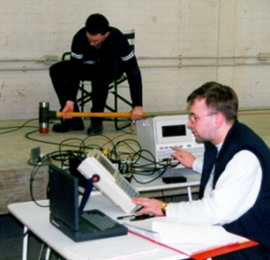
Impact testing may be undertaken using an instrumented hammer or a heel-drop on an instrumented force plate. In the case of an instrumented hammer, the force is measured by a load cell installed at the tip of the hammer. The excitation usually moves from point to point while the responses are measured at a number of stationary reference points. At each point, the excitation is applied several times to average out the effects of extraneous noise. To minimise the detrimental effects of unmeasured extraneous excitation of the floor, the testing should be performed on an unoccupied floor structure, preferably in an unoccupied building. Therefore, for floors in operation or under construction, night and weekend work is often the only option. An instrumented hammer test is shown.
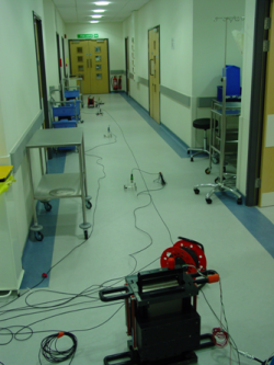
Shaker testing may be undertaken using a single shaker or an array of shakers distributed over the floor area. The excitation is generated by a moving shaker armature of known mass. This mass is driven by a signal generated by a spectrum analyser that is also used to acquire all of the force and response data. The use of a shaker overcomes the problems with extraneous noise encountered with impact testing. A considerable enhancement of the shaker excitation at a single point of the floor is achieved by multiple uncorrelated random shaker excitation applied simultaneously over a number of test points distributed over the floor area. A typical shaker test is shown .
[top]Response measurement
There are many situations in which the client, building owner or occupant might want to measure the response of a floor in service. In this case, the aim of the test will be to measure directly the acceleration caused by a realistic excitation event. The measured acceleration may then be compared against the specified limit for the floor, in order to verify its acceptability. Typically, for office floors, the appropriate excitation event is a single person walking.
After the in-situ determination of the natural frequencies and mode shapes of the floor, as described above, the floor can be classified as low or high frequency. The type of walking test which needs to be carried out will depend on this classification. As low frequency floors can be excited close to their resonant frequency, by frequencies of one or more harmonics of walking, it is important to maintain the pacing rate of the test subject to generate the higher harmonics. For example, if resonance of a floor needs to be excited at 6Hz, the pacing could be set to two steps per second (2 Hz), so that its third harmonic excites the 6 Hz mode. The use of a metronome might be useful in maintaining a steady pace. In the case of high frequency floors, there is no need to adjust the pacing rate to excite the resonant frequencies (since resonant build up does not occur in this type of floor). Usually, a range of pacing frequencies is specified, e.g. from 1.4 Hz to 2.2 Hz in increments of 0.2 Hz.
After determining the required pacing rate(s), a walking path must be selected. This will depend on the utilisation of the floor. For example, there may be cases when walking paths only along planned corridors are considered relevant. Finally, a test subject is asked to walk several times along the walking path, during which responses are measured at a number of pre-selected points on the floor. These may be at positions of maximum amplitude for the mode shape under consideration or at sensitive locations (e.g. in hospital operating theatres).
In addition to these short tests, requiring an unoccupied building, technology now exists whereby long-term monitoring of floor vibrations can be performed. One or more vibration transducers can be installed on the floor and left to acquire vibration response data, due to everyday normal floor usage by its occupants, over a prolonged period of time.
[top]Regulations and design rules
BS EN 1990[5], Annex A1.4.4 states that vibration should be limited to avoid discomfort to users, and to ensure the functionality of the structure or structural members. It states that the acceptability criteria may be given in terms of a frequency limit, or can be determined using ‘a more refined analysis of the dynamic response of the structure, including the consideration of damping.’ It lists a number of possible sources of vibration, including walking, synchronised movement of people and machinery that should be considered and refers the reader to ISO 10137[6] for further guidance.
BS EN 1993-1-1[7] states that ‘the vibrations of structures on which the public can walk should be limited to avoid significant discomfort to users, and limits should be specified for each project and agreed with the client.’ The UK National Annex[8] refers to specialist literature for more detailed advice.
The two main codes used in the UK which cover floor vibrations are:
- ISO 10137:2007[6] Bases for design of structures - Serviceability of buildings and walkways against vibrations
- BS 6472-1:2008[2] Guide to evaluation of human exposure to vibration in buildings.
ISO 10137[6] gives recommendations on the evaluation of serviceability against vibrations of buildings and walkways for human occupancy, the contents of the building and the structure of the building.
BS 6472-1[2] provides guidance on predicting human response to vibration in buildings over the frequency range 0.5 Hz to 80 Hz. Frequency weighting curves for human beings exposed to whole-body vibration are included, together with advice on measurement methods to be employed. Methods of assessing continuous, intermittent and impulsive vibration are presented. The code also describes how to determine the vibration dose value, VDV, from frequency-weighted vibration measurements.
These codes specify multiplying factors to limit the value of calculated response factors to achieve ‘low probability of adverse comment’ for different building types. In 1989, SCI proposed a series of multiplying factors which are larger than those proposed in the codes. These are provided in SCI P354. Similar values are also recommended by the AISC/CISC DG 11[9] (American code for vibration) which leads to a more economical design.
For the case of health buildings, HTM 08-01[10] sets out the vibration design criteria for healthcare premises. These are shown in the table below.
| Space | Response factor for continuous vibration |
|---|---|
| Operating theatre, precision laboratory, audiometric testing booth | 1 |
| Wards | 2 |
| General laboratories, treatment areas | 4 |
| Offices, consulting rooms | 8 |
SCI P354 ‘Design of floors for vibration: A new approach’ presents the details of the response factor method to assess the performance of the floors subject to different sources of vibration. This publication, which includes worked examples, is becoming increasingly popular in the industry and widely recognised as a good practice for design.
[top]Structural design considerations
[top]Damping
The damping ratio (ξ), in typical steel framed buildings depends on type of the connections, degree of fit-out, furnishings, etc. The typical values shown in the table should be used in design unless more accurate information is available.
| Damping ratio (ξ) | Floor finishes |
|---|---|
| 0.5% | For fully welded steel structures, e.g. staircases |
| 1.1% | For completely bare floors or floors where only a small amount of furnishings are present |
| 3.0% | For fully fitted out and furnished floors in normal use |
| 4.5% | For a floor where the designer is confident that partitions will be appropriately located to interrupt the relevant mode(s) of vibration, i.e. the partition lines are perpendicular to the main vibrating elements of the critical mode shape |
[top]Floor loading
It is important that the distributed mass used in vibration analysis is representative of the mass that will be present in service, as a higher mass will reduce the response of a floor at a given frequency. In design, the mass per unit area should be taken as the unfactored self-weight of the structure including superimposed dead loads such as the weight of ceilings and services. In addition, where the designer can be confident that such loading will exist in the finished structure, an allowance may be included for semi-permanent loads (this loading should not be included for dance or aerobic floors).
According to the UK National Annex to BS EN 1990, 30% of the imposed load should be included when considering deformation at serviceability limit state. However, this is likely to be inappropriate for floor vibrations because, in reality, the actual imposed load will be considerably less than the prescribed design loads on the floor. Hicks et al.[11] recommend that the allowance should not exceed 10% of the nominal imposed load.
[top]Modelling issues
Due to the small strains encountered during a vibration response, the normal assumption that beams and slabs are simply supported is not necessarily valid. When the strains are insufficient to overcome friction, the beams and slabs will act as if they were structurally continuous, even where nominally pinned connections are used. In this case, a more accurate result will be obtained by modelling the joints as rigid connections.
Also non-structural elements, e.g. partitions, can significantly affect the vibration performance of floors. Their influence is complex however and partitions may be reconfigured over time. Therefore the beneficial influence of partitions is generally not included in the structural models.
The methods presented for evaluating natural frequencies of beams are broadly applicable to cantilevers. However, due to the ineffective mobilisation of mass near to the free end of the cantilever, the simplified method of calculating response can be unsafe and should not be used. Designers should only use the general procedure (finite element analysis) for cantilevers.
[top]Continuity and isolation of critical areas
The structural response is dependent on the floor mass participating in the dynamic movement. Designers may influence the floor response by taking measures to control the extent of floor participation. Where a greater mass is required, designers should seek to maximise the area of floor participating in the response by way of floor plate continuity. Conversely, where specific areas are especially sensitive to vibration, it may be desirable to isolate these areas from the rest of the floor.
A floor which has not been designed to be continuous when loaded statically, may act as such under dynamic conditions. If a floor plate is continuous over a beam, or if the beam provides continuity, the floor plate can generally be considered continuous for dynamic performance. For composite beam applications, care must be taken to ensure that transverse reinforcement is provided, as its absence can lead to a worsening of vibration performance over time, as cracks form and continuity is lost.
To isolate an area of floor, it must be structurally separated from the rest of the floor. This may be achieved by the provision of construction joints all around the edges. Alternatively, the stiffness of the floor may be increased locally; this has the effect of isolating the area.
[top]Precast concrete units in composite design
Precast units with an in situ concrete topping and supplementary continuity reinforcement will behave in a similar manner to a metal decking composite floor system, if connected to the supporting beams through shear connectors, or if trapped between the flanges of the beams (e.g. shallow floor construction). However, if shear connectors are not provided to the supporting beams, the area considered to participate in the motion should correspond to half the beam span multiplied by half the beam spacing.
If a structural topping is not provided to the precast units, the designer should be aware that there is a danger that the units could vibrate independently from one another. This will result in a high response, owing to the relatively low effective mass participating in the motion.
[top]Architectural design considerations
[top]Walking paths
Some areas of a floor will have a higher response than others due to the mode shapes of the vibration. Generally, areas close to beams and columns will be less responsive than areas in the middle of a slab as these form nodal lines, i.e. limited or no motion. By locating walking paths closer to these less responsive areas, many vibration issues may be eliminated.
In addition to location, the length of the corridor should be considered. The longer the corridor, the greater the time associated with the walking activity. Reducing corridor lengths or breaking-up the corridor into smaller lengths reduces the duration of any given walking activity and may prevent the build up of a resonant response.
[top]Location of aerobic areas
Aerobic areas are, by their very nature, likely to experience a high dynamic response. Due to continuity of the floor, this response may be transmitted into other areas of the building. It is, therefore, advisable to take care when positioning aerobic areas to ensure that the affected floor locations do not exhibit a response that would be considered unacceptable. Ideally, office, residential and other communal locations should not be placed close to areas where rhythmic activities are likely to take place.
[top]Case studies


[top]References
- ↑ BS EN 1991-1-4:2005+A1:2010, Eurocode 1. Actions on structures. General actions. Wind actions, BSI.
- ↑ 2.0 2.1 2.2 2.3 2.4 BS 6472-1:2008, Guide to evaluation of human exposure to vibration in buildings. Vibration sources other than blasting, BSI.
- ↑ BS 6841:1987 Guide to measurement and evaluation of human exposure to whole-body mechanical vibration and repeated shock, BSI
- ↑ NA to BS EN 1991-1-1:2002, UK National Annex to Eurocode 1. Actions on structures. General actions. Densities, self-weight, imposed loads for buildings, BSI.
- ↑ BS EN 1990:2002+A1:2005. Eurocode: Basis of structural design. BSI
- ↑ 6.0 6.1 6.2 ISO 10137:2007 Bases for design of structures. Serviceability of buildings and walkways against vibrations, International Organisation for Standardization.
- ↑ BS EN 1993-1-1:2005+A1:2014, Eurocode 3: Design of steel structures. General rules and rules for buildings, BSI
- ↑ NA+A1:2014 to BS EN 1993-1-1:2005+A1:2014, UK National Annex to Eurocode 3: Design of steel structures General rules and rules for buildings, BSI
- ↑ Design Guide 11: Floor Vibrations Due To Human Activity (Second Edition), American Institute of Steel Construction, 2016.
- ↑ 10.0 10.1 Health Technical Memorandum 08-01, Acoustics. Department of Health, 2013
- ↑ Hicks, S.J., Brozzetti, J., Remy, B. and Lawson, R.M. Dimensionnement Des Planchers Mixtes Acier Beton vis-à-vis des Vibrations Construction Metallique No.1, pp 3-31, 2003 (in French).
[top]Further reading
- Steel Designers' Manual 7th Edition. Editors B Davison & G W Owens. The Steel Construction Institute 2012, Chapter 13, Structural vibration
- Ellis, B.R. On the response of long-span floors to walking loads generated by individuals and crowds, The Structural Engineer, 78(10), May 2000, pp 17-25.
[top]Resources
- SCI P354: Design of floors for vibration: A new approach (Revised Edition), 2009
- Floor response calculator
- Steel Construction: Floor Vibration, BCSA, 2016
[top]See also
- Cost of structural steelwork
- Healthcare buildings
- Composite construction
- Long-span beams
- Multi-storey office buildings
- Residential and mixed-use buildings