


Design of steel footbridges
Footbridges are needed where a separate pathway has to be provided for people to cross traffic flows or some physical obstacle, such as a river. The loads they carry are, in relation to highway or railway bridges, quite modest, and in most circumstances a fairly light structure is required. They are, however, frequently required to give a long clear span, and stiffness then becomes an important consideration. The bridges are often very clearly on view to the public and therefore the appearance merits careful attention.
Steel offers economic and attractive forms of construction which suit all the requirements demanded of a footbridge.


[top]Introduction

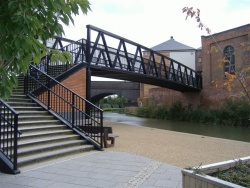
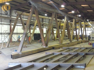
(Image courtesy of Nusteel Structures Ltd.)
A fully detailed design can be prepared with other contract documents for pricing by tenderers. However, it is common practice, particularly for smaller bridges, for the detailed design of a footbridge to be included as part of a design and construct package. Many fabricators are able to provide such a package, using methods and details of construction developed to suit their particular fabrication facilities and expertise. However, the engineer supervising the work still needs to be acquainted with the different forms of construction which might be used and to be aware of their advantages and limitations.
Longer span bridges and those which form part of a larger scheme are likely to be designed in detail by a consultant or local authority. Within such an organisation the engineer carrying out the design needs to be familiar with the particular requirements for footbridges, their features and construction details.
For the engineer in either of these situations, this article presents guidance on the conceptual design of steel and composite footbridges, to aid the selection of an outline design.
[top]Features and forms of construction for footbridges
[top]Basic requirements

Footbridges, like any other bridge, must be long enough to clear the obstacle which is to be crossed and high enough not to interfere with whatever passes beneath the bridge. However, the access route onto the footbridge is often much different from what is familiar to the designer of a highway bridge: there is no necessity for a gentle horizontal alignment (indeed the preferred route may be sharply at right angles to the span). Structural continuity is therefore less common. The principal span is often a simply supported one.
Provision of suitable access for wheelchairs and cyclists is often specified for footbridges. Access ramps must be provided and restricted to a maximum gradient. The consequent length of ramps where access is from the level of the road or rail track over which the bridge spans is generally much longer than the bridge itself. The form of construction suitable for the ramps may have a dominant influence on the final form of the bridge.
The width of a footbridge is usually quite modest, just sufficient to permit free passage in both directions for pedestrians. Occasionally the bridge will have segregated provision for pedestrians and cyclists, in which case it will need to be wider. Parapets are provided for the safety of both the pedestrians and traffic flow. Footbridges over railway lines are required to have higher parapets and be provided with solid panels directly over the rail tracks.
[top]Truss and Vierendeel girder beams
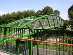
Trusses offer a light and economical form of construction, particularly when the span is large. The members of the truss can be quite slender and this naturally leads to the use of structural hollow sections. Hollow sections have been used for footbridges for over 50 years and some fabricators have specialised in this form of construction, developing techniques and details which utilise them to the best advantage.
Vierendeel girders using hollow section members offer an alternative but complementary structural form of similar proportion by substituting a rectangular form for the triangular arrangement used in trusses.
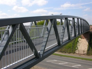
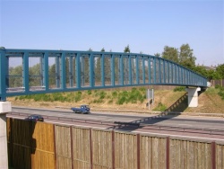
- Warren truss through footbridge
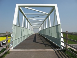


Trusses and Vierendeel girders are arranged with either half-through or through construction. Half-through construction is used for smaller spans, where the depth needed is relatively shallow. For larger spans, or where the truss is clad to provide a complete enclosure for the pedestrians, through trusses are used; the top chords are then braced together above head level.
[top]Steel beam bridges

The simplest method of employing structural steel as the prime structural element of a footbridge is to use a pair of girders (fabricated or rolled sections), braced together for stability and acting as beams in bending, with a non-participating walkway surface on top. A typical small bridge deck might for example be formed by timbers placed transversely across the top of the beams. Precast slabs might also be used, without a shear connection to the steel and therefore not participating in global structural action.
Alternatively, the floor might be formed by steel plate, suitably stiffened to carry the pedestrian loads, in which case the plate could also be made to act structurally as the top flange of the steel beams.
[top]Steel box girder bridges
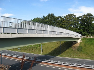
Another alternative is to use a small steel box girder. The top flange acts as the floor of the bridge, and there are usually short cantilevers either side of the box. This form has the benefits of good torsional stiffness, which can simplify support arrangements and clean surfaces which minimise maintenance.
[top]Composite beam bridges
Composite beams, steel girders with a concrete slab acting as both a walkway floor and participating as a top flange, are a practical solution for medium span footbridges. They are a lighter version of the form of composite construction frequently employed in highway bridges. Slabs may be cast in situ, though the lesser requirements for the shear connection and the lighter design loads on the slab allow greater opportunity to employ precast slabs. The slab can also be cast on the beams in the works or other convenient site, since the weight and dimensions are often sufficiently modest to permit transport and erection of the complete superstructure.
Although composite construction is usually associated with I section girders, a concrete slab can also be used with a steel box girder.
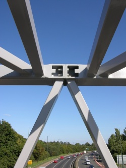
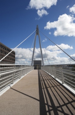
[top]Cable stayed bridges

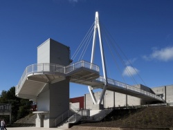
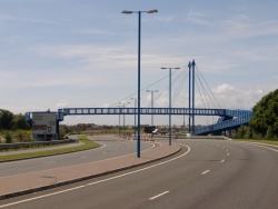
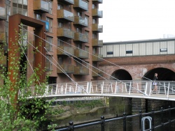
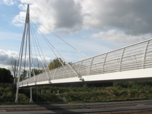
In seeking to provide a bridge of light appearance, the use of cable stays is found to be very successful. It often affords scope to create a visually striking structure which provides a landmark or a focus for the area in which it is located. Almost any form of construction can be used with stays, though when a cable stayed form is chosen, the structural requirements are often found to be of secondary consideration to the achievement of a pleasing appearance.
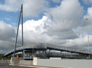
Examples of cable-stayed bridges include:
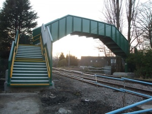
[top]Enclosed bridges
Enclosure of the sides of a footbridge is often called for to discourage the throwing of objects from the bridge. This is a particular requirement for bridges over railway lines. Full enclosure, to the sides and the roof of the walkway, is called for in situations where the users are to be protected from the environment and where greater protection is required over railway lines. Such enclosure justifies the use of through truss or Vierendeel construction. The form of construction will probably be dictated by consideration of appearance of the bridge and its relationship to adjacent structures. Whilst the general principles discussed in this guide are applicable, fully enclosed bridges are not specifically dealt with in detail here.
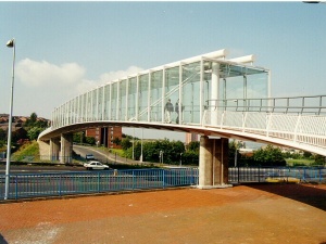
Enclosure at Oldham Way Footbridge
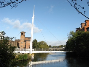
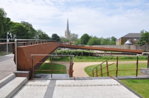
Decorative spike at Cathedral Green Footbridge


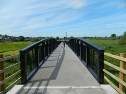
[top]Decorative features
In addition to the basic impression made by the form of construction, the appearance can be greatly influenced by non-structural decorative features, such as parapets and handrails. Where particular effects are sought, the availability of different patterns for posts, rails, etc, should be investigated. Non-structural embellishments of supports can also contribute – for example a cable stayed pylon can be extended to a spike or other feature above the level of the topmost stay connection, as shown on the Cathedral Green Footbridge (above right).
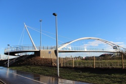
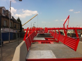
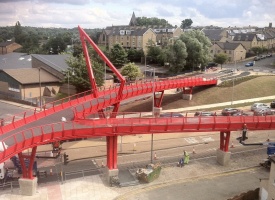
[top]Landmark structures

It is an increasingly common requirement for footbridges in prominent or key locations to be ‘landmark structures’. Particular attention is given to the appearance of the structure and this may result in somewhat unusual forms of construction. Such structures can be allowed to be marginally less efficient (in terms of complexity of fabrication) but if the design is well executed the penalties should be small.
There is more scope for innovative design when the structure is not over a road or railway, because the requirements for parapet details need not be so stringent. Parapets are often the most noticeable feature of a footbridge, and the freedom to use more attractive forms and more open post and rail arrangements can lead to a very pleasing appearance.
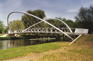
The use of curved arch-type members is currently quite popular, as is the use of cable stays. Some notable examples are illustrated in the case studies in this article.
[top]Conceptual design and detailing
[top]General arrangement
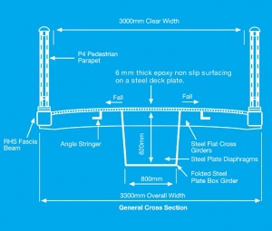
As a first step, the basic requirements for access and safety should be determined. The width and form of access needed depends on the expected pedestrian traffic flow, though minimum dimensions are adequate in most cases.
For a simple footway, a minimum clear width of 2.0 m is required by the highways authorities. Railway station footbridges can be less wide. To the sides of this footway, parapets are required, which should be 1.15 m high over roads or 1.5 m high over railways, the height measured from the footway surface in both cases. In areas prone to vandalism, a height of 1.8 m may be required over railways. An increased parapet height of 1.3 m may be needed in areas of high prevailing wind and for bridges where the headroom under the bridge is more than 10 m.
Where pedestrians and cyclists share the pathway, a minimum width of 3.5 m may be used for low traffic flows but a wider segregated pathway may be required for higher traffic flows. Segregation can be achieved by a white line, colour contrast or difference in surface texture, in which case the minimum width is (1.5m + 2.5m). Alternatively, a kerb or railings may be used, which increases the width requirements further. At the same time the minimum parapet height is increased to 1.4 m.
Dimensional requirements for footbridges are given in CD 353[1]. Although that document refers to requirements in CD 377[2], which in turn refers to BS 7818[3] for pedestrian restraint systems.
The drainage requirements also affect the cross section, since kerbs will be needed to prevent run-off where the bridge is above a carriageway, a footpath or rail tracks. Typically an upstand of 50mm should be provided. This upstand can be provided by an edge beam, by the lower chord of a truss or by a flat welded to the floor plate.
[top]Span
Since there is usually no need to align the approaches to a footbridge, the span should normally be arranged square to the obstacle it has to cross.
The minimum span required is that simply needed to clear the width of obstacle, carriageway or railway. However, the span may be increased in order that the supports are positioned far enough from a carriageway or rail track to avoid the risk of impact from an errant vehicle or derailed train. The supports of light structures such as footbridges are particularly prone to the effects of impact.
For footbridges over highways, the span is determined by the dimensions of the carriageways, as given in CD 127[4].
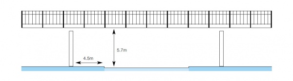
To avoid the imposition of impact loads the supports need to be set back 4.5 m from the edge of the carriageway (see Figure 1 below). Where this can be arranged, perhaps additionally spanning a footway beside the road, the consequent savings in the cost of the substructure should be considered. Supports between carriageways should also be avoided if possible.

The space needed for approach ramps and stairs will be significant in arranging the layout of a footbridge. This may influence the positioning of the bridge and its supports, and thus its span.
Footbridges over railways are mostly required to cross two or four tracks, with resulting span of between 10 and 25 m. Where intermediate supports are placed closer than 4.5 m to the nearest rail, Network Rail requires the superstructure to be capable of supporting itself if one support were to be demolished in an accident.
[top]Clearance

(Image courtesy of Nusteel Structures Ltd.)
Over a highway, the clearance under new footbridges is required to be at least 5.7m (CD 127[4]). With this clearance the superstructure need not be designed for impact loads (see Figure 1 above). If any relaxation on clearance were permitted in special cases it is likely that impact loads would have to be considered. This would be very onerous on the structural design.
Clearance required over a railway line depends on several factors, such as whether the line is electrified and the ‘category’ of the line. Requirements must be agreed with Network Rail for the particular situation.
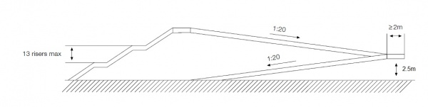
Clearly, where access to the bridge has to come from carriageway or track level, the rise needed for the stairs or ramps is the sum of the clearance plus the superstructure construction depth (walkway surface to structure soffit). This means that ramps will be long (about 120 m at each end of the bridge over a road, for a 1 in 20 grade). It also means that the depth of construction (for example the depth of a plate girder) can add significantly to the length of ramp, and thus to the cost of the whole structure. For this reason, half-through construction, with a very shallow construction depth, is usually preferred.
Sufficient vertical camber is needed to ensure drainage of the footbridge to the ends, where the run-off can be carried to drains or a soakaway.
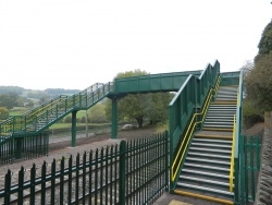
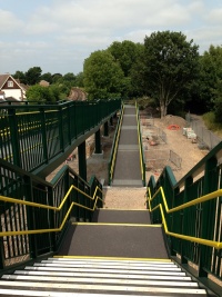
[top]Stairs and ramps
Where access is required from a lower level, stairs and ramps must be provided. Stairs are only suitable for able pedestrians and it is general policy to provide ramps where possible. Such ramps should ideally be no steeper than 1 in 20, though gradients of up to 1 in 12 may be used in cases of extreme difficulty.
A ramp can be either a series of straight sections or a spiral, depending on circumstances and space available (see Figure 2 below). The space occupied by a ramp is quite significant and may well influence the position of the bridge.

A single straight ramp can be used where space and the desired access route permit. If the gradient is steeper than 1 in 20, the ramp should have intermediate landings (i.e. it should be a series of ramps with horizontal sections between). Ramps are often arranged in scissor fashion (i.e. with a 180° change of direction at an intermediate landing).
Spiral ramps must have a minimum inside radius of 5.5 m (gradient measured 900 mm from the inside edge). The same limits on gradient apply (i.e. a maximum of 1 in 20 is desirable, up to 1 in 12 may be acceptable in some cases). Spiral ramps are unsuitable for a full 6 m rise to a footbridge over a highway unless a large radius can be accommodated.
Stepped ramps are sometimes used which, with a 125 mm step and a 1 in 12 slope between, can effectively achieve a 1 in 6 gradient. For spiral ramps this gives a rise of 6 m in under 360° turn.
Stairs are usually arranged in two or three flights with intermediate landings, depending on particular arrangements, to comply with normal safety requirements. They usually have semi-open risers, for lighter appearance. Handrails are provided on the inside faces of the parapets on stairs and ramps. Minimum widths must be maintained between these handrails. Gallery of images:
- Examples of stairs and ramps
Seabraes Footbridge
(Image courtesy of S H Structures Ltd.)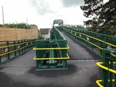
Scissor ramp
(Image courtesy of Briton Fabricators Ltd.)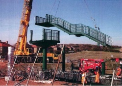
Installation of stairs
(Image courtesy of Cairnhill Structures Ltd.)


[top]Services

(Image courtesy of Briton Fabricators Ltd.)
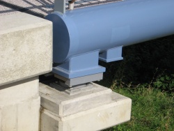
Occasionally the bridge may have to carry a service – water pipes or electric cables, for example. It should normally be arranged that such pipes are supported out of sight, on brackets or cross-members between main beams for example. If a service is positioned inside a box girder, it is better to put it in a duct, so that any maintenance to the service does not require entry into the box girder. Gas or water pipes should not be sited inside a box girder, for safety reasons, unless placed in a steel sleeve which runs the length of the bridge.
[top]Selection of type of construction
As mentioned previously, the depth of construction is very important to the overall extent of the footbridge where access is from the level of the road or railway being crossed. In those circumstances it is usually preferable to use a half-through form of construction. This usually leads to a selection of a truss or Vierendeel girder bridge, though half-through plate girder forms such as that developed by Network Rail may also be used.
However, not all bridges are subject to such constraints. Some simply cross, for example, a small river, or span across a deep cutting. In such cases the depth of construction is not so important and steel girders or steel composite construction may be employed. When the span is long, the dynamic response of the bridge becomes a significant consideration, particularly for the lighter all steel bridge. The greater stiffness afforded by truss construction may well be advantageous. Alternatively, cable stayed construction can be employed.
Cable stayed forms of construction can rarely be justified visually below about 40m. For spans up to 100 m a single pylon on one side of the main span is often appropriate, both visually and structurally. Beyond about 100 m twin pylons should be considered.
Suspension bridges are very rarely considered these days, but may still be chosen for appearance reasons when the span exceeds about 70 m.
A summary of approximate span ranges suitable for the various types is given below.
| Construction type | Span range (m) |
|---|---|
| Truss | 15 – 60 |
| Vierendeel girder | 15 – 45 |
| Twin steel girders | 10 – 25 |
| Steel girders + steel floor plate | 10 – 30 |
| Steel box girder | 20 – 60 |
| Composite beams | 10 – 50 |
| Arches | 25 upwards |
| Cable stayed bridge | 40 upwards |
| Suspension bridge | 70 upwards |
[top]Trusses and Vierendeel girder bridges
Although trusses and Vierendeel girders have a different structural action, there are many similar features when they are constructed of structural hollow section members, as used in footbridges. This section deals with both types of construction.
[top]Through and half-through construction
Trusses and Vierendeel girders for footbridges are normally arranged with the deck at the level of the bottom chord, in either through or half-through construction. Half-through construction is used for smaller spans, where the depth needed is less than the clearance height for people to walk through. For large spans, or where the bridge is clad to provide a complete enclosure for the pedestrians, through construction is used.

(Image courtesy of Briton Fabricators Ltd.)
The top chords can then be braced together above head level.
Stability of the top compression chord in half-through construction is provided by the U-frame action of the side members and the cross-members of the deck. In through construction, lateral bracing between the two top chords offers a more direct means of stabilising them.
[top]Configuration
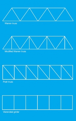

The type of truss usually employed is either a Warren truss or a modified Warren truss. Occasionally a Pratt truss may be used. The different types are illustrated in Figure 3 (right).
Warren trusses are the simplest form of truss, with all loads being carried principally as axial loads in the members and with the minimum of members meeting at joints. However, the loads which are carried to the bottom chords from the walkway floor can lead to significant bending in these members when the panels are large. A modified Warren truss reduces the span of these chord members, though the additional vertical members add complexity to the fabrication. Pratt trusses are used where it is preferred that some members are vertical, for example to facilitate the fixing of cladding or decorative panels.
Vierendeel girders have no diagonal members and rely on a combination of axial loading and bending to carry loads. The stiffness of the girder depends crucially on the bending stiffness of vertical and horizontal members and on the stiffness of the joints between the two. As a consequence they are much heavier, for a given span, than a Warren truss. However the appearance, which only shows vertical and horizontal lines, in harmony with the normal form of parapet (horizontal rails, vertical posts and infill), is often considered more pleasing.
For the largest spans, the Vierendeel girder will probably be too flexible, though they have been used successfully up to 45m span.
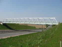
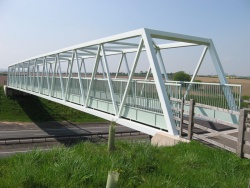
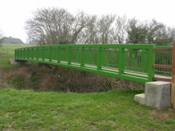
- Warren truss half-through footbridges
(Image courtesy of Nusteel Structures Ltd.)

(Image courtesy of Nusteel Structures Ltd.)
(Image courtesy of Nusteel Structures Ltd.)


[top]Proportions and appearance
The familiar image of a truss is probably of a heavy looking structure, relatively deep in proportion to span. Such trusses were often used for railway bridges. However, a truss footbridge can generally be of light appearance and of shallow depth/span proportion.
With half-through construction, the minimum overall depth is determined by the parapet height; for a crossing over a highway the minimum is about 1.25 m. For spans over about 30 m the depth will need to be slightly greater, though span/depth ratios in excess of 30 can give a pleasing appearance.
For spans over 50 m full through construction will probably be necessary. Then the depth is determined by internal clearance, which is usually specified as 2.3 m minimum. To reduce the tunnel effect and to keep the top bracing away from casual abuse a depth of about 3 m is needed. Such spans will have a deeper span/depth ratio, though the slender members will still give an impression of lightness.
The arrangement of the bracing and the line of the parapets are the dominant features which are seen by road users. They therefore require careful attention and treatment.

(Image courtesy of Briton Fabricators Ltd.)
Where the depth of the Vierendeel girder is determined by parapet height, the top chord can often be used as the parapet rail, with suitable infill bars fixed between the vertical members. For longer span Vierendeel girders, where the depth is more than the parapet height, parapet panels complete with top rail can be fixed inside the rectangular panels of the girder. Where a truss is used, the parapet is usually fixed to the inner face of the diagonal members. The parapets are less conspicuous to road users than the truss members, though they are still evident in silhouette.
Construction depth, from footway surface to underside of the truss or girder, is normally quite shallow, not more than the depth of the chord members. This contributes greatly to the light appearance.
The top and bottom chords of a truss are usually made parallel, but for larger spans a less dominating appearance can be achieved by a hog-back configuration, with a gentle curve to the top chord reducing the depth at the ends of the span.
[top]Members and connections – trusses

Both circular and rectangular structural hollow sections are commonly used in trusses. The bottom chord is generally rectangular, to facilitate connection with deck and cross-members. Rolled sections or flats are sometimes used as cross-members or as stiffeners to steel floor plates. Chords and diagonals are usually arranged with centrelines intersecting where possible. Standard welding details have been developed for hollow section connections.
For half-through trusses the connection with cross-members at the lower chord requires particular attention, since its stiffness and strength are fundamental to U-frame action.
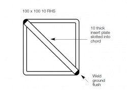
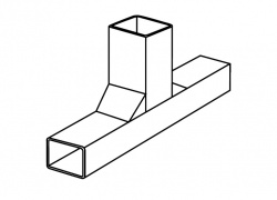
Where the bottom chords are of rectangular section, some designers specify plates slotted diagonally across the section at the position of the cross-members (Figure 4 right) to prevent the chord lozenging or distorting, thus increasing the stiffness of the joint.
Where a steel floor plate is used it normally acts as the “bracing” to the bottom chords, to carry the lateral shear (mainly wind forces) back to the supports. If a non-participating form of floor is used, cross bracing in the plane of the bottom chord, to resist lateral forces, must be considered.
Through trusses, used in longer spans, give lateral stability to the top compression chord by means of bracing in the plane of the top chord. Such bracing will also share in the carrying of any lateral forces, especially where the truss is clad on its sides and thus subject to significant wind loads. At the ends of the span these lateral forces have to be carried down to bearing level through portal action or through a braced frame.
[top]Members and connections – Vierendeel girders
In footbridges, Vierendeel girders normally use rectangular hollow sections for greater stiffness and strength at the connections between verticals and chords.
- Vierendeel girder half-through footbridges
(Image courtesy of Nusteel Structures Ltd.)
(Image courtesy of Nusteel Structures Ltd.)
(Image courtesy of Nusteel Structures Ltd.)


The nature of Vierendeel action is that vertical shear is carried by shear/bending action of each length of chord, and the vertical members are subject to complementary horizontal shear and bending. Since shear is highest at the ends of the span, the “fixed end moments” are highest there also. The vertical members therefore need to be strongest at the ends of the span.

On the other hand the central portions of the chords sustain predominantly axial load, whilst the ends sustain predominantly bending load. There is less need to vary the size of the chord members, and usually only thickness is varied, if at all.
The consequences are that the vertical members are often wider (in the plane of the girder) at the ends of the span and are sometimes closer together, variations which are clearly visible in silhouette.
The strength of the joint between chord and vertical members must be adequate to transmit the fixed end moments. To do this, both should have the same width (normal to the plane of the girder). Under the higher moments on the joints toward the ends of the span a simple square joint may have inadequate strength, and either triangular fillets (cut from the same section as the vertical) or reinforcing plates may need to be added to increase stiffness and strength (see Figure 5 right). The appearance of these additions may not always be acceptable and heavier sections may be preferred.
Stability of the compression chord again requires U-frame action of the cross section and this again requires adequate stiffness and strength of the cross-member to vertical connection at the bottom chord. Even with the heavier sections usually required for a Vierendeel girder, it may be necessary to insert diagonal plates, as mentioned previously.
[top]Floor construction

(Image courtesy of Briton Fabricators Ltd.)
The floor of a truss or Vierendeel girder footbridge will usually be of steel plate, though precast planks have been used with trusses. The lighter steel deck is now generally preferred.
The plate, typically 6 mm or 8 mm thick, is supported on and welded to steel cross-members between the chords. These cross-members form part of the U-frames which stabilise the top chord and are themselves usually hollow sections. The plate panels between chords and cross-members are divided transversely and sometimes longitudinally by stiffeners (usually flats) to give added support.
On top of this plate a waterproof layer is required for corrosion protection, and to give a non-slip surface for safety. This is usually achieved with a thin membrane (which acts both as waterproofing and as a binder) and a surface dressing of fine aggregate. The total thickness is about 4 mm. This surface is often applied in the works and does not add significantly to erection weights.
When precast planks are used it is necessary to provide a shelf angle on the inner face of the chords on which the planks can sit. It is very important that the joint between concrete and steel is properly sealed or it could become a moisture and corrosion trap.
Where drainage over the edges of the bridge is not permitted, arrangements must be made to carry rainwater to the ends of the bridge and then to drains or a soakaway. A vertical curve or longitudinal camber should be provided on a bridge which otherwise would be level.
Where rainwater can be allowed to run off the side of the bridge (for example over a river), the floor may be slightly cambered transversely to facilitate drainage. With stiffened thin steel plate decks, care also needs to be exercised that panels do not dish between stiffeners and allow ponding of water – the spacing of stiffeners is usually limited for this reason. Weld sizes should be kept to a minimum, to reduce distortion from welding (see Guidance Note 2.10).
[top]Parapets

(Image courtesy of Nusteel Structures Ltd.)
Parapets are normally designed to comply with a DMRB standard. The parapet may be either a separate item or may be combined with structural members.
For trusses, the parapet is provided as separate units fixed to the inside faces of the truss diagonals. The diagonals must then be designed to carry lateral loads from the parapet, and the parapet rails must be designed to span between the diagonals which support them. Parapet posts can alternatively be fixed to the footway deck, though the attachment would need to be strong enough to withstand the overturning moment arising from lateral forces on the top rail.
Where Vierendeel girders are used it is convenient to fix parapet panels in the rectangular panels of the girders, effectively using the vertical members as parapet posts. This achieves an integrated appearance and produces a slightly lesser overall width of bridge than with separate parapets on the inner faces of the girder. The top chord of the girder may also function as the top parapet rail, or, if it is higher than the required parapet height, a separate rail can be provided in addition to the top chord.
[top]Cladding
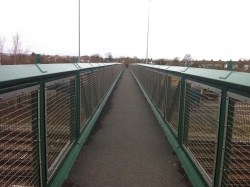

(Image courtesy of Briton Fabricators Ltd.)
Over rail tracks, the highway and rail authorities require that solid non-climbable cladding be provided on the inside face of the truss or Vierendeel girder. To prevent unauthorised access, not only must the pedestrian face of the bridge be designed to be non-climbable, it must also be impossible to climb along the outer face from the ends of the bridge – this usually means that trusses are clad either side of the diagonals at the ends. The top flanges, chords or parapets must be arranged so that they are impossible to walk along.
Such cladding is usually achieved by profiled steel sheeting, rigidized aluminium, GRP panels or even flat sheets. Fine mesh (maximum 50 mm apertures) may be used over non-electrified lines. Although the cladding is only required over the tracks, a better appearance is often achieved by providing the cladding over the full length of the span. Great care needs to be exercised in detailing the cladding, to avoid the creation of small inaccessible sheltered ledges on the top of the lower chord where moss and debris can accumulate or which may be used for handholds or footholds.
[top]Supports
Trusses and Vierendeel girders are supported either on bearings (if they span between concrete abutments, for example) or directly on top of a simple steel substructure without any bearings.
At abutments the point of support is normally directly below the end vertical or diagonal members and thus does not give rise to local bending of the chord section. Other supports should also preferably be arranged similarly. Where it is not convenient to do so, for instance when a top landing cantilevers a short distance beyond the support columns and the support is midway between bracing connections, the bottom chord is subjected to bending. It is then common to use a heavier chord section over the last one or two panels of the truss.
[top]Fabrication of trusses
Fabricators who specialise in hollow section fabrication are familiar with all the types of detail needed for truss footbridges and have appropriate equipment, such as profile cutting equipment for tubulars etc.
A wide range of sizes of hollow sections is available from the rolling mills, but it must be remembered that the fabricator has to purchase material for each job, either from the mill or from a stockist, and his orders may be subject to minimum quantities and premiums for small quantities. The designer should therefore try as far as possible to standardise his choice of section size and material grade.
[top]Erection
Fortunately, most footbridges can be fabricated as a complete length of the span and then transported, with spans up to about 45 m. Although fabrications over 27 m in length require special permission to travel on the public highway, most fabricators prefer to complete fabrication in the works wherever possible and are familiar with arrangements for the movement of long lengths.
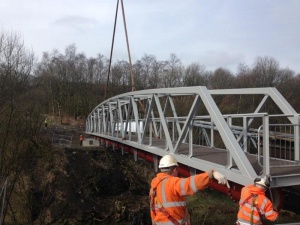
- Installation of a complete span
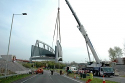
(Image courtesy of Briton Fabricators Ltd.)
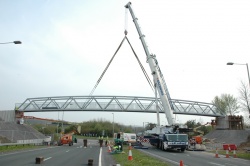
(Image courtesy of Briton Fabricators Ltd.)


Bolted hollow section flanged joint details can be used for site splices, though it may be felt that flange plate end connections are somewhat cumbersome in appearance. In-line splice details are much less obtrusive, but require more effort in design and fabrication. In most cases, spans must be complete before lifting, because closure or possession periods will be very short.
[top]Steel beam bridges
[top]Types of construction
Four types of construction are considered in this section:
- a pair of steel beams with a non-structural floor on top (e.g. timber)
- a pair of steel beams with a structurally participating steel floor plate
- a steel box girder
- a half-through plate girder bridge, as developed by Network Rail and its predecessors.
The first three are appropriate where depth of construction is not important. The fourth is appropriate where minimum construction depth is critical.
[top]Proportions and appearance

For the relatively light loading on a footbridge, the depth of beam in all cases can be arranged to be about 1/30 of the span. A typical bridge over a river or canal might then have a span of 30 m and a beam depth of 1 m. A simple I-beam bridge with non-structural floor might comprise two girders about 1.5 m apart on which is fixed a floor of, in some instances, timber planks. Parapet posts would be fixed to the top flange or the outer face of the steel beams.
Steel girders with a structural participating steel floor plate would be of similar overall proportions. Parapets would be fixed on top of the floor plate.
With both forms, the girders can have a clean web over their full length, as web stiffeners are needed only at supports and on the inner faces for attachment of bracing. The structural element therefore looks clean and simple. The appearance will be influenced strongly by the treatment of the parapet rails, posts and any other feature added to the bridge. The use of simple parapet details will contribute to a good non-fussy overall appearance.
In some circumstances a distinct curvature in elevation (more than would suffice just to aid drainage to the ends) will add character to the appearance.
The use of a steel box girder extends the clean lines to the soffit of the bridge. It can be complemented by a simple basic parapet or can be contrasted by embellishment with ornate fixtures and fittings. Typically the box would be about 1.0 m wide, with short steel cantilevers either side to provide the necessary width.

(Image courtesy of Nusteel Structures Ltd.)
Half-through plate girder bridges will usually have their U-frame stiffeners on the outside faces and generally look heavier. Nevertheless, the half-through plate girder bridge developed by British Rail achieves a pleasing appearance.
[top]Members and connections – I-beams/girders
For economical design, the pair of beams need to be braced together to stabilise them against lateral torsional buckling. Bracing at several positions in the span will be necessary, roughly at 15 to 20 times the top flange width to achieve reasonable limiting stress levels. Bracing can simply be an X-brace with single tie at each position, bolted to stiffeners on the inside faces of the webs. For the main girders, fabricated I-sections are likely to be lighter and more economic than Universal Beams. Castellated beams can provide a weight saving in some circumstances whilst offering an interesting and different appearance.
A non-structural deck, such as timber planking, can be simply bolted down to the top flange of the I-beams. Particular attention should be paid to detailing, to minimise crevices where dirt and moisture can accumulate.
In many instances steel plate is used for the floor of the bridge. The plate, typically about 6 mm or 8 mm thick, is usually welded to the main girders and can therefore be assumed to act structurally with them. Cross-members will be required to carry the floor loading to the main beams and these are sometimes extended by short steel cantilevers outside the beam web, in which case an edge beam is provided to give a neat face and to give support to the parapet. A thin waterproof wearing surface is normally specified, dressed with fine aggregate for grip and durability. The surface is often applied in the works.
[top]Members and connections – box girders

Box girders are essentially similar to the paired plate girders with steel deck, as described above, except that the bottom flange joins the two webs and encloses the space between. They are usually considered only for spans over about 30 m. The thickness of the top flange which also forms the floor plate will be determined by overall bending strength rather than local floor loading. The plate is typically supported by transverse stiffeners which cantilever to edge beams. Two or three longitudinal stiffeners may be provided to stiffen the floor plate when acting as the compression flange of the box.
Diaphragms are needed at supports and are often provided at several positions along the length of the girder (typically the third points) to control distortion. Large holes will be required in the diaphragms if access is required during fabrication or maintenance.
To improve appearance it is common to use slightly sloping webs, creating a trapezoidal cross section.
The use of steel box girders has the advantage of torsional strength and stiffness. They can be used in continuous construction to simplify supports or to curve the bridge in plan when desired for appearance. In a straight bridge, torsional restraint (usually by means of twin bearings) is needed only at the ends: a single bearing will suffice at intermediate supports, thus allowing the use of a single slender column.
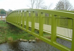
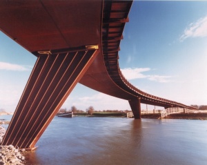
- Curved box girder footbridge
Jarrold Bridge, Norwich
(Image courtesy of S H Structures Ltd.)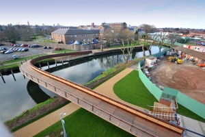
Jarrold Bridge, Norwich
(Image courtesy of S H Structures Ltd.)


[top]Members and connections – half through girders
Half through plate girder footbridges are often used over railways. The solid web provides the required screening without the need for any non-structural additions. This form has developed from the half-through plate girder concept often seen in railway bridges. Two features to note are: the use of a hollow section as top flange, turned through 45° it forms a steeple cope, which discourages walking along the flange; the absence of any projection of the bottom flange prevents climbing along the outer face.
U-frame action is provided by the flat intermediate stiffeners to web and bottom flange. Typically they are provided about every 1.5 m.
[top]Parapets
Where there are no cantilevers the parapet can either be fixed to the top flange of the box or to the web of the girder. The attachment positions should coincide with bracing or cross-members, to provide restraint against rotation under lateral loads on the parapet rail.
Where there are cantilevers, either the posts should coincide with the cantilever positions or they should be mounted on a torsionally stiff hollow section edge beam.
- Parapet posts at cantilever positions
(Image courtesy of Briton Fabricators Ltd.)
(Image courtesy of Briton Fabricators Ltd.)


[top]Fabrication
Whether using rolled I-beams or fabricated I-section girders, the processes of drilling holes, adding stiffeners etc. poses no difficulty to the fabricator. The fabricated I-section can either be made using jigs and semiautomatic welding or by a T and I automatic welding machine. Curvature in elevation is easily achieved with fabricated girders, and universal beams can readily be curved by specialist bending companies prior to fabrication. Fabrication of box sections requires more traditional methods, and the completion of the closed box makes it almost essential for manual work internally. Details should be arranged for ease of access for work and inspection.
[top]Splices
For spans up to around 40 m, it is quite likely that the beams would be transported full length and splices would not be needed. Over 40 m they would be split into at least two lengths; site connections would normally be bolted.
Bolted splices are quite conventional, with few problems. If a completely clean face is sought, it will be necessary to have a site welded joint.
[top]Composite beam bridges
[top]Types of construction

Composite construction is seen in footbridges in two forms – a concrete slab on top of two I-girders or a concrete slab on top of a closed steel box girder. The open steel box form with slab which is sometimes used in highway bridges is not normally seen in footbridges
Slabs may be cast insitu, though the relatively modest extent of the shear connection and lighter design loads on the slab allow greater opportunity to employ precast slabs. Such slabs are provided with open pockets to fit over the shear connectors. The pockets and the joints between slab sections are filled with concrete to create the necessary structural continuity.
[top]Proportions and appearance
Composite footbridges typically have a span/depth ratio of about 20 (depth measured from top of slab to underside of girder).
Short cantilevers outside the lines of the webs will give a better appearance, in the same way as they do for highway bridges. A small upstand is needed at the edges to provide a mounting for the parapets and to act as a drainage upstand. A thick edge beam would create a rather heavy appearance.
[top]Members and connections
Composite construction produces a much heavier structure than an all-steel footbridge; the dead load accounts for over half of the total load in most cases. The extra weight and consequent stiffness of this form of construction has the advantage of being less responsive to dynamic excitation.
Where transverse joints between precast units are not designed to carry transverse shear, plan bracing will also be needed.
[top]Floor construction
Reinforced concrete slabs for footbridges are typically about 150 mm thick. They can be constructed in situ on falsework or by using precast slabs.
Sometimes they can be cast in the fabrication yard, and the complete composite structure transported to site and erected.
A waterproofing membrane is required, plus some form of durable wearing surface. A combined membrane and wearing course with aggregate dressing, similar to that used on steel decks, can be used.
[top]Parapets
As for other forms of construction, parapets must comply with DMRB or Network Rail requirements. The parapet posts are fixed to the concrete slab or edge beam with conventional holding down bolts.
[top]Cable stayed bridges
Footbridges carry only relatively light loading. However, when the main span is long, the requirements of supporting its own dead load and of providing a sufficiently stiff structure lead toward a much more substantial structure than would seem appropriate for a “mere” footbridge. As a result, an increasingly popular solution for longer spans is the use of a cable stayed arrangement. This effectively divides the span into shorter lengths, for which lighter beams can be used. The pylons for these bridges also add a strong visual feature which is often welcomed.
[top]Types of construction
Cable stays can be used with any of the forms of construction previously described, though to complement the light appearance, a slim form of deck construction is likely to be more appropriate for all except the largest spans. Supports can be provided to the main beams at about 10m to 15m spacing, which facilitates the use of a slender deck.
For most footbridges, twin planes of cable stays will normally be used, one to each side of the bridge deck. A pylon at one end of the main span will suffice up to about 100 m span. Very long spans may require the use of pylons at both ends. 'A' frame pylons are popular, with the two stay planes inclined. Alternatively, individual pylon legs for each cable plane can be arranged, or a “goal-post” arrangement can be used; the stays can then lie in a vertical plane.
- A selection of cable stayed footbridges
(Image courtesy of Nusteel Structures Ltd.)
(Image courtesy of Briton Fabricators Ltd.)
(Image courtesy of S H Structures Ltd.)


Usually, at least two forestays should be provided in each plane – a single stay is hard to justify on economic or appearance grounds. The minimum span for a cable stayed bridge with two forestays is thus around 35 m.
A single backstay is usually sufficient, anchored to the girder at the abutment which supports the end of the backspan. Further backstays are only needed if the backspan is long and requires intermediate support. The stays are normally anchored at floor level to longitudinal beams. The beams need to be stiff and strong enough to span between anchor points and they may need to be fairly deep. A lighter appearance, with shallow beam/floor depth, might be achieved by using a Vierendeel girder and half-through construction. Footbridge pylons are usually steel box or circular sections, for slender appearance, ease of construction and economy.
[top]Members and connections

(Image courtesy of Briton Fabricators Ltd.)
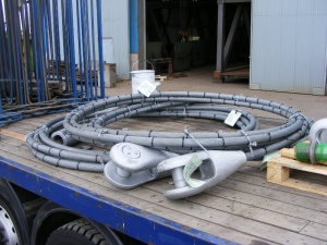
The cable stays will normally be made from wire rope or spiral strand. Strands are made by winding together, or laying up, a number of galvanized steel wires. Ropes are made up of a number of small strands wound together. Ropes and spiral strands have a lower effective modulus than solid steel. Parallel wire strands are also available. Advice should be sought from specialist manufacturers on the selection of strands.
In the dead load condition the stays are effectively prestressed. It is important to calculate accurately the stretch of the stays in the dead load condition, so that the correct geometry of the structure is achieved. Provision should be made for length adjustment in the stays, to accommodate tolerances and errors.
Stays must obviously be sufficiently strong to support the beams, but often more significant for small bridges is the need to provide sufficiently stiff supports to the beams and to avoid slack stays which will be easily vibrated.
With twin planes of stays, the natural arrangement for the deck structure is with main beams at either edge, to which the stays are attached. The floor then spans transversely between the beams. A single plane of stays can only be used where a torsionally stiff box girder is provided; the stays would be attached on the centreline of the bridge. This is not normally convenient for a single footway.
As well as provision for adjustment in length during installation, attachment details should also be arranged such that any stay can be replaced if need be. It is good practice to make sure that the anchorages are as strong at ULS as the breaking load of the stays.

Under the action of live load the stays provide stiff support to the main beams and they thus behave essentially as continuous beams. Axial load is also transmitted to the beams by the stays, so the beams must be designed for the combined load effects.
For very long spans, the deflection under load changes the geometry of the structure. If the sag of the stays is significant they will act as non-linear springs. Both these effects should be taken into account in the analysis. Computer programs are available which automatically take account of the non-linear effects of varying geometry under load.
Whilst ropes and strand can last the life of the bridge, experience has shown that they should be inspected from time to time to check for corrosion and fatigue, particularly at the lower ends, and may need to be replaced. The stay anchorages should be accessible for such inspection and maintenance. The design should also be such that any one stay can be removed and replaced.
[top]Dynamic response
Cable stayed bridges are relatively flexible and are more prone to oscillation under wind or under deliberate excitation by users. An all-steel construction results in a very low level of structural damping, which can allow the oscillations to grow significantly. The dynamic response of the bridge should therefore be checked carefully. Artificial damping, such as tuned mass dampers, can be provided if necessary.
[top]Floor construction
Deck construction is usually of stiffened steel plate, though timber or reinforced concrete are sometimes used instead.
[top]Access ramps and stairs

(Image courtesy of Briton Fabricators Ltd.)
Where approach ramps or stairs are needed they are usually structurally independent, except for the need to be supported at the top end either on the footbridge superstructure or on a common substructure support. They can therefore be of a structurally different form. However, it is generally preferable to achieve harmony of appearance between the two and to use a similar construction form.
Stairs usually require, at most, one intermediate support beneath the landing at mid-flight. Ramps require more supports and indeed are small bridges themselves. Even for ramps, the number of intermediate supports should be kept as small as possible, with spans of at least 10m. Supports should also be as simple as possible – a T-shaped column and crosshead should be sufficient in most cases (provided that resistance to impact is not necessary).
Where supports may be subject to impact loads, they will need to be significantly more substantial. The foundations will also have to be larger. In these circumstances the designer can choose either reinforced concrete columns or a robust steel structure.
Since landings are nominally level, care needs to be exercised to avoid ponding of water and accumulation of debris. Extra drain holes in these areas together with a small fall will suffice.
Handrails must be provided on the inside faces of parapets on stairs and ramps, for safety reasons. A clear gap of at least 40 mm is desirable between the rails and any adjacent members.
Stairs normally have semi-open risers. Fully open risers are not permitted by CD 353[1].
At the bottom of flights of stairs, details should be chosen which avoid acute corners, since they can trap debris. To avoid this, stairs can be supported just above the bottom of the flight, so that there is a clear gap between the underside of the stringers and ground level.
[top]Bearings and expansion joints
The provisions for restraint or the accommodation of movement due to expansion or other reasons depends very much on the general arrangement of the bridge, ramps and stairs.
- Hunslet Moor Footbridge
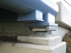
Bearing and jacking point
Bearing and jacking point
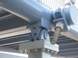
Link pin and cable anchorage


When the bridge spans between bankseats or abutments, expansion joints are needed, and the structure will sit on bearings. At one end the bearings may be fixed longitudinally, but if laminated elastomeric bearings are used, both ends can be 'free', as long as the bearings can transmit any longitudinal forces.

(Image courtesy of Briton Fabricators Ltd.)
Expansion joints need to accommodate a thermal movement range that depends on span – for a 50 m length, a range of about 40 mm is required at SLS. Allowance for tolerances in the length of the superstructure can usually be accommodated during installation. Even at ends which are longitudinally restrained there has to be some provision for movement at deck level, owing to rotational movements under live load.
For footbridge expansion joints, a simple detail should be chosen, one which does not collect dirt or debris and which can be dismantled for maintenance if required. A simple leaf plate fixed to the bridge on one side and sliding on a second plate on the fixed side can usually be arranged in most circumstances. Particular attention should always be given to the avoidance of steps facing uphill, even as little as 5 mm, since they always tend to accumulate material washed down by run-off.
Where the bridge spans between steel column supports, no bearings are needed. The bridge is simply bolted down to the tops of the columns. Expansion is accommodated by flexing of the columns and no expansion joints are needed.
Consideration should be given to fixing long ramps at the bottom end. Maximum longitudinal movement at the far end therefore occurs where the columns are tallest and most able to accommodate it.
Stairs should preferably be fixed at the bottom and bolted to column supports. This effectively provides a restraint for any ramp or bridge connected to the top of a straight flight.
For light all-steel bridges, all support details, bearings or direct connections to columns, should be designed to resist at least a nominal uplift.
[top]Design codes, standards and guidance
[top]British Standards
In most circumstances, the Eurocodes will apply to the design and construction of footbridges. For design of steel and composite structures, the following Parts of the Eurocodes are applicable:
- BS EN 1990 Eurocode[5]
- BS EN 1991 Eurocode 1: Actions on structures[6]
- BS EN 1992 Eurocode 2: Design of concrete structures[7]
- BS EN 1993 Eurocode 3: Design of steel structures[8]
- BS EN 1994 Eurocode 4: Design of composite steel and concrete structures[9]
The Eurocodes are issued in numerous Parts, covering all aspects of design. For bridges, ‘Part 2’ of Eurocodes 2, 3 and 4 apply, along with other parts covering general rules.
Dimensional and safety requirements for stairs are given in BS 5395-1[10]. These requirements are amended slightly by the departmental standard for footbridges.
[top]Departmental standards

(Image courtesy of Angle Ring Co. Ltd.)
The requirements of the UK highways authorities in England, Scotland, Wales and Northern Ireland are set out in the Design Manual for Roads and Bridges (DMRB), published by The Stationery Office and available online. This manual is a collection of individual standards and advice notes.
The use of the Eurocodes is implemented through the Technical Approval system, procedures for which are set out in BD2/12. Several other standards and advice notes also relate to the design of footbridges. Design criteria for footbridges are given in CD 353[1] and CD 377[2]. Highway cross sections and headroom are given in CD 127[4], which specifies a minimum clearance for footbridges of 5.7 m. This avoids the necessity of applying the impact requirements on the superstructure (defined in BS EN 1991-1-7[11] and its National Annex[12]), which would be particularly onerous on a light structure such as a footbridge.
Where supports need to be close to the edge of the carriageway, they are required to be provided with protective plinths and designed for impact loads. Where they can be kept back from the carriageway, perhaps to span a footway beside the road, the consequent savings in the cost of the substructure should be considered. Supports between carriageways should also be avoided (unless they can be located more than 4.5 m from the road, which is not usually feasible).
The design of parapets on footbridges is covered by CD 377[2] and BS 7818[3].
[top]Railway standards
Numerous standards are published by the Rail Safety and Standards Board (RSSB), some of which are Railway Group documents. Document GCGN5612[13] provides guidance on the application of the Eurocode loading due to accidental actions and aerodynamic effects.
Network Rail’s requirements and recommendations are set out in NR/L3/CIV/020[14].
[top]Design of hollow section joints

(Image courtesy of Nusteel Structures Ltd.)
The design of hollow section joints is covered in Part 1-8 of Eurocode 3[15]. The rules are based on extensive background research into the behaviour of tubular joints and on guidance published by CIDECT.
For triangulated structures, where the joints transmit essentially axial loads from one member to another, the design of the joint involves checks on:
- the adequacy of the welds at the end of the member and
- the bending of the walls of the hollow sections (which are subjected to out of plane forces).
Rules for joints which transmit in-plane moments (as in a Vierendeel girder), are given in the Eurocode, although it should be noted that these only cover T joints, not the corner joints at the end of a span. A stiffer and more efficient joint is achieved when the bracing member is the same width (normal to the moment plane) as the chord member. Adequacy of both the bracing member and the chord member must be checked. If necessary, reinforcement of the joint can be designed.
[top]Design of cable stayed and suspension bridges

(Image courtesy of Nusteel Structures Ltd.)
For general guidance on the design of cable stayed bridges, reference should be made to standard texts, such as Walther[16] or Troitsky[17]. These are comprehensive books, but they do include specific comment on footbridges with illustrated examples.
Part 1-11 of Eurocode 3[18] covers the design of tension components such as wire ropes or and bars. The design of the anchorages is not separately covered but the general rules in Eurocode 3 can be applied.
Guidance on the design of suspension bridges can be found in texts such as Pugsley[19]. The tensile elements may be wire rope or strand, as for cable stayed bridges, though high tensile steel rods may be used for the main tension members.
[top]Design of steel and composite beam bridges
Guidance on the design of composite highway bridges is given in publications by The Steel Construction Institute (P356, P357) and P393). These can be used as general guidance in the design of footbridges, although of course the loading is significantly different.
Guidance on a wide range of practical aspects related to steel bridge construction is given in a series of Guidance Notes produced by the Steel Bridge Group and issued as SCI publication P185.
[top]Dynamic response
Serviceability criteria for the dynamic response of footbridges are given in Annex A2 of BS EN 1990[5]. The vertical natural frequency of many footbridges will be below 5Hz and the response must be checked. If the horizontal natural frequency is less than 1.5Hz, checks must be made for possible lateral excitation.
The susceptibility of a footbridge to aerodynamic excitation is covered by Annex E of Part 1-4 of Eurocode 1[20] but the UK National Annex[21] refers instead to PD 6688-1-4[22]. The evaluation of dynamic characteristics is covered in Annex F of Part 1-4 of Eurocode 1[20]. Bridges under 30m span are unlikely to be susceptible.
[top]Protective treatment

(Image courtesy of Nusteel Structures Ltd.)
For bridges subject to highways authority requirements, the protective treatment specifications should be selected from those listed in Series 1900[23] of the Specification for Highway Works (SHW). When using Series 1900[23] and the associated NG1900[24], access conditions should normally be taken as “difficult”, which will result in use in use of a multi-coat ‘Type II’ system. Galvanizing may be suitable for small components, such as parapets.
Network Rail’s requirements for protective treatments to be used on bridges are given in the following documents.
NR/L3/CIV/039[25] defines the requirements for the assessment, certification, registration and specification of protective coatings and sealants for use on Network Rail’s infrastructure. NR/L3/CIV/040[26] defines the requirements for the selection and use of protective coating systems, and NR/GN/CIV/002[27] supports NR/L3/CIV/040[26] by providing guidance and information on the selection, and application of such systems.
For other bridges, the SHW specifications, or alternatives, may be used, with the client’s agreement.
In some circumstances, Weathering Steels might be used.
[top]Steel materials
Steel material for plates, rolled sections and structural hollow sections is covered by British Standards BS EN 10025[28] and BS EN 10210[29]. Information about the products available from steelmakers can be obtained from relevant product brochures.
[top]Case studies


[top]References
- ↑ 1.0 1.1 1.2 CD 353 Design criteria for footbridges. The Design Manual for Roads and Bridges. The Stationary Office
- ↑ 2.0 2.1 2.2 CD 377 Requirements for road restraint systems. The Design Manual for Roads and Bridges. The Stationary Office
- ↑ 3.0 3.1 BS 7818:1995, Specification for pedestrian restraint systems in metal. BSI
- ↑ 4.0 4.1 4.2 CD 127 Cross-sections and headroom, The Design Manual for Roads and Bridges. The Stationary Office
- ↑ 5.0 5.1 BS EN 1990:2002+A1:2005. Eurocode: Basis of structural design. BSI
- ↑ BS EN 1991 Eurocode 1. Actions on structures. (Various Parts). BSI
- ↑ BS EN 1992 Eurocode 2. Design of concrete structures. (Various Parts). BSI
- ↑ BS EN 1993 Eurocode 3. Design of steel structures. (Various Parts). BSI
- ↑ BS EN 1994 Eurocode 4. Design of composite steel and concrete structures. (Various Parts). BSI
- ↑ BS 5395-1:2010, Stairs. Code of practice for the design of stairs with straight flights and winders. BSI
- ↑ BS EN 1991-1-7:2006+A1:2014. Eurocode 1: Actions on structures. General actions. Accidental actions. BSI
- ↑ NA+A1:2014 to BS EN 1991-1-7:2006+A1:2014, UK National Annex to Eurocode 1. Actions on structures. General actions. Accidental actions. BSI
- ↑ GCGN5612 Guidance on Loading Requirements for the Design of Railway Structures (Issue 2), Railway Safety and Standards Board, London, 2018
- ↑ NR/L3/CIV/020: Design of bridges (Issue 1), Network Rail, 2011
- ↑ BS EN 1993-1-8:2005. Eurocode 3: Design of steel structures. Design of joints, BSI
- ↑ Walther, R. et al, Cable stayed bridges, Thomas Telford, London, 1988
- ↑ Troitsky, M. S., Cable-stayed bridges, BSP, Oxford, 1988
- ↑ BS EN 1993-1-11:2006, Eurocode 3. Design of steel structures. Design of structures with tension components, BSI.
- ↑ Pugsley, A. The theory of suspension bridges, Edward Arnold, London, 1957
- ↑ 20.0 20.1 BS EN 1991-1-4:2005+A1: 2010 Eurocode 1. Actions on structures. General actions. Wind actions, BSI
- ↑ NA to BS EN 1991-1-4:2005+A1: 2010, UK National Annex to Eurocode 1. Actions on structures. General actions. Wind actions, BSI
- ↑ PD 6688-1-4:2015, Background information to the National Annex to BS EN 1991-1-4 and additional guidance, BSI
- ↑ 23.0 23.1 Manual of Contract Documents for Highway Works: Volume 1 - Specification for Highway Works, Series 1900 Protection of steelwork against corrosion, August 2014, The Stationery Office
- ↑ Manual of Contract Documents for Highway Works: Volume 2: Notes for Guidance on the Specification for Highway Works, Series 1900: Protection of Steelwork Against Corrosion. The Stationary Office, August 2014
- ↑ 25.0 25.1 NR/L3/CIV/039: Specification for the assessment and certification of protective coatings and sealants (Issue 5), Network Rail, 2009
- ↑ 26.0 26.1 26.2 NR/L3/CIV/040: Work Instruction for the use of protective coating systems (Issue 2), Network Rail, 2019
- ↑ 27.0 27.1 NR/GN/CIV/002: The use of protective coatings and sealants (Issue 5), Network Rail, 2009
- ↑ BS EN 10025:2019, Hot rolled products of structural steels. (Various parts), BSI
- ↑ BS EN 10210:2019, Hot finished structural hollow sections of non-alloy and fine grain steels (Various parts), BSI
[top]Resources
- Hendy, C.R.; Iles, D.C. (2015) Steel Bridge Group: Guidance Notes on best practice in steel bridge construction (6th Issue). (P185). SCI
- Iles, D.C. (2010) Composite highway bridge design. (P356 including corrigendum, 2014). SCI
- Iles, D.C. (2010) Composite highway bridge design: Worked examples. (P357 including corrigendum, 2014). SCI
- Iles, D.C. (2012) Design of composite highway bridges curved in plan. (P393). SCI
- Iles, D.C. (2015) Determining design displacements for bridge movement bearings. (P406). SCI
- Steel Bridges: A practical approach to design for efficient fabrication and construction, 2010, (Publication no. 51/10), BCSA,
- Guide to the Erection of Steel Bridges, 2005, (Publication no. 38/05), BCSA
- British sections product range datasheets, British Steel
- Celsius® Hot finished hollow sections to EN 10210. 2022, Tata Steel
[top]See also
- Sustainable steel bridges
- Multi-girder composite bridges
- Ladder deck composite bridges
- Integral bridges
- Half-through bridges
- Box girder bridges
- Tied-arch bridges
- Material selection and product specification
- Weathering steel
- Bridges - initial design
- Modelling and analysis of beam bridges
- Design of beams in composite bridges
- Shear connection in composite bridge beams
- Design for half-through construction
- Fatigue design of bridges
- Bracing systems
- Stiffeners
- Connections in bridges
- Bridge articulation and bearing specification
- Plan curvature in bridges
- Skew bridges
- Specification of bridge steelwork
- Design for steel bridge construction
- Corrosion protection
- Welding
- Preloaded bolting
- Accuracy of steel fabrication