


Design of beams in composite bridges
In typical beam and slab composite bridges, such as seen in multi-girder bridges and ladder deck bridges, the design of the beams needs to consider two basic situations – when the steel beams act alone to support the weight of wet concrete and when the steel beams act compositely with the slab (at later stages of construction and during service). This article discusses the principal design considerations for both situations.
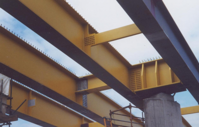

(Image courtesy of Mabey Bridge Ltd.)
[top]Forms of bridge beams
In composite bridges, rolled section steel beams are rarely used for the main girders – it is more economic to use plate girders in which the plate sizes and thicknesses are chosen for greatest efficiency. The consequences are that:
- Flanges can be equal or unequal
- Hybrid sections comprising plates of different strengths are possible
- Girders can be straight or curved in plan
- Girders can be straight or curved in elevation to suit the road profile
- Girders can be of variable depth, with straight or curved soffits
- Girders can be of uniform or variable section along their length (e.g. variable flange thickness)
The design must accommodate all these possible variations. Additionally, web thicknesses are often thin relative to their depth and then the local buckling of the web may need to be taken into account (which is not usually the case for rolled sections ).
[top]Verification of design resistances
The Eurocodes distinguish between the resistance of cross sections of members and the buckling resistance of lengths of member between positions of restraint. The bending resistance of the cross section should be verified at every cross section. The Eurocode rules give the value of design resistance moments for a beam related to its cross-section. The buckling resistance of the member over a discrete length between restraints must also be verified. Typically, the buckling resistance of the member will govern, rather than the resistance of the most highly stressed cross section. Cross section resistance and buckling resistance are discussed separately below, both for bare steel beams and for composite beams.
[top]Cross section resistance of steel beams
[top]Local buckling and section classification
Local buckling is a secondary instability problem involving the buckling of individual steel elements within the cross-section of a structural member, such as the flange outstands or web. Such local buckling is fundamental to the behaviour and therefore to the design of all structural components carrying compressive stress. This compression arises from either compression force or bending moment. Classification of a steel section is therefore one of the first tasks to be undertaken in design. There are four classes of cross section:
- Class 1 – The section can form a plastic hinge and has sufficient rotational capacity to maintain this moment over a considerable range of in-plane rotation
- Class 2 – The section can develop plastic resistance but has limited rotational capacity to act as a hinge
- Class 3 – The section can develop elastic resistance of the full cross-section
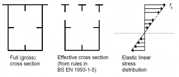
- Class 4 – Local buckling of slender elements reduces the elastic resistance; the section can develop elastic resistance of an effective cross-section, smaller than the full section.
In bridges, plastic global analysis is rarely used, so Class 1 offers no benefit over Class 2.
The classification of a cross section depends on the width to thickness ratio of the parts of the section subject to compression. This includes all parts of the cross section either totally or partially in compression under the action combination considered. In general, it is possible for flanges and webs to be in different classes and a cross section is usually classified by the highest (least favourable) class of its component parts. However, it is also permitted to define a section by quoting both the flange classification and web classification separately. Table 5.5 in BS EN 1993-1-1[1] gives maximum width to thickness ratios for compression parts to be used to determine section classification. The tables are generic and account for cases of pure compression, pure bending or a combination of bending and compression for internal compression parts, outstand flanges, angles and tubular sections.
[top]Bending resistance of steel cross sections
The basic requirement for cross-section bending resistance is to verify that
![]()
where MEd is the design bending moment and Mc,Rd is the design resistance moment for the bending of the steel or composite beam (based on either the plastic resistance, Mpl,Rd, or elastic resistance, Mel,Rd). Different approaches to cross-section bending resistance design are required depending on the class of the section.
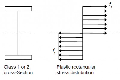
For Class 1 and 2 sections, the design resistance of the cross section corresponds to a fully plastic internal stress distribution as shown below. The resistance moment is therefore given by
![]()
However, it should be noted that the plastic section modulus Wpl can only be derived solely from the geometry if the yield strength is the same for all parts of the cross section. Where yield strength varies (thicker elements generally have a lower yield strength) the resistance moment should be determined directly from the plastic stress blocks.

Class 3 cross-sections can develop compressive yield at their extreme fibres (defined in EN 1993-1-1[1] as being at the mid-plane of a flange rather than its outer surface) but will fail by local buckling if this yielding starts to spread further into the cross section. The maximum resistance is therefore reached when the extreme compression fibre reaches yield. If partial plastification of the tension zone is not considered in design, the resistance will be reached when the stress from an elastic stress distribution reaches yield at either fibre, whether compressive or tensile, as shown below.
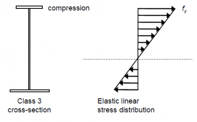

The resistance moment is then given by:
![]()
where Wel,min is the section modulus at the fibre with maximum stress.
If the limiting fibre is on the tensile side, partial plastification of the tension zone of the web may be considered, although this is often ignored. The development of partial plastification is shown below.
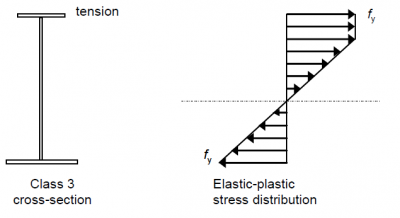

The resistance moment is then determined by assuming plane sections remain plane, a bilinear stress-strain curve and by balancing forces in the tension and compression zones. Note that the neutral axis will move as plasticity spreads throughout the tension zone and this can then affect the section classification, hence why partial plastification is usually ignored.
Class 4 sections fail by local buckling before they reach yield. Two approaches are given in EN 1993-2[2] to determine the bending resistance of such sections:
- Limiting stress method
- Effective area method
For the limiting stress method, the gross cross-section is used. The resistance moment is deemed to be obtained when the weakest panel in compression fails by local buckling. This method can often be conservative as it does not allow for the shedding of load between panels.
The more usual approach is to use the effective area method, where the resistance moment is obtained when yield is reached at an extreme fibre of the effective cross-section as shown below (for the more general case of a box section, when both the flange and the web might be class 4).

The resistance moment is then given by:
![]()
where Weff,min is the smallest elastic section modulus of the effective cross section.
Rules for determining effective areas of slender elements are given in EN 1993-1-5[3]. For further discussion on the design of Class 4 sections, refer to the Thomas Telford Designers’ Guide to EN1993-2 [4].
[top]Shear resistance of steel cross sections
Two routes are provided in Eurocode 3 to determine shear resistance:
- Shear resistance of cross-sections where the web is not prone to shear buckling (EN 1993-1-1[1], Clause 6.2.6)
- Shear resistance of cross-sections where the web is prone to shear buckling (using the stiffened plate rules of EN 1993-1-5[3], Clause 5.2)
The latter is more usual for bridge beams since most have slender webs. Clause 5.2(2) of EN 1993-1-5[3] gives the limits for slenderness as noted below.
[top]Shear resistance without shear buckling
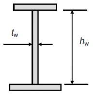

Beams with stocky webs are not susceptible to shear buckling and can attain the full plastic shear resistance, which, for rolled section welded beams, is given by:
![]()
where hw and tw are as defined in the figure right. The factor η is recommended in EN 1993-1-5[3] to be taken as 1.2 for steel grades up to S460, which means that the shear resistance of a stocky web exceeds its resistance based on the usual Von Mises yield stress in shear of fy/√3. This enhancement is justified from tests which show that strain hardening allows a higher resistance to be attained without excessive deformation occurring, although the UK National Annex[5] limits η to a value of 1.0, due to other test results which show that the enhancement is not applicable to all steel grades.
Shear buckling resistance
The resistance of steel beams to shear buckling is covered by the stiffened plate rules in EN 1993-1-5[3] and is based on the rotated stress field theory proposed by Höglund. Webs become susceptible to shear buckling when the height to thickness ratio, hw/t, exceeds certain limits. These limits are:

Rotated stress field model (Höglund)
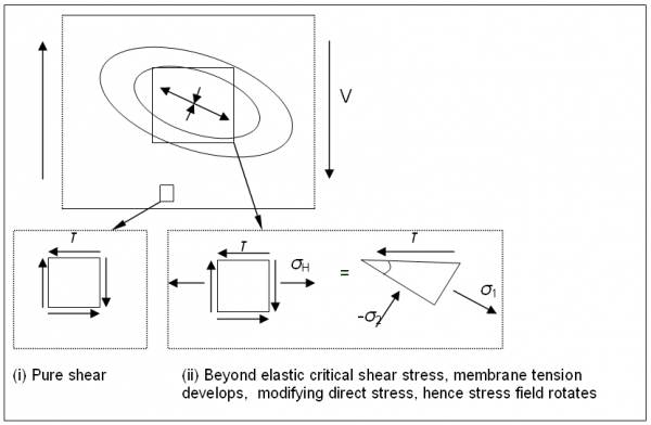
The rotated stress field model used for shear buckling involves a 3-stage development of shear resistance as indicated diagrammatically below.
- Initial development of pure shear up to the point where the web (or web panel for stiffened webs) buckles in an elastic shear buckling mode
- Further development of shear resistance by means of a diagonal band of tensile stress (similar to tension field model but without the associated compression forces in transverse web stiffeners). Beyond the elastic critical shear stress, the development of membrane tension modifies the direct stress, hence the stress field rotates
- Final enhancement of the resistance by the restraint of the tensile band by the top and bottom flanges


Thus it can be seen that, in general, the elastic shear resistance of steel beams has a contribution from the web and a contribution from the flanges. The resistance expression given in EN 1993-1-5[3]. takes the following form, clearly identifying the two separate contributions:

Contribution to shear resistance from web
The contribution to shear resistance from the web is given by:

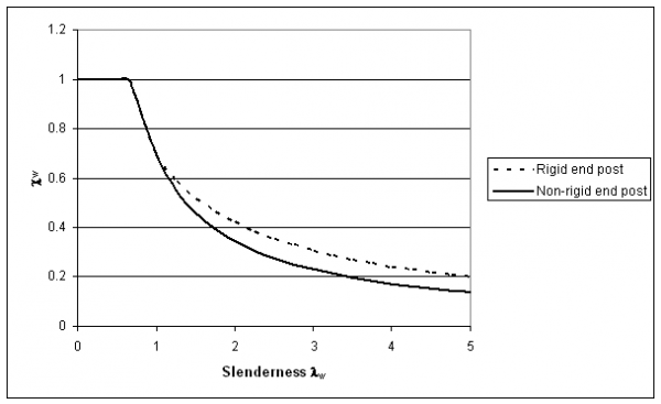
The value depends on web slenderness and end post condition. Rigid end posts are typically used at the ends of girders to improve their shear resistance. They comprise two double-sided stiffeners and are designed to resist the longitudinal web membrane forces that develop in the rotated stress field model discussed above. The rigid end post case also applies at intermediate supports in continuous beams because of the continuity of the web.
The reduction factor, ![]() , depends on web slenderness
, depends on web slenderness ![]() as well as the end post condition. The web slenderness is given by:
as well as the end post condition. The web slenderness is given by:

The shear buckling coefficient, kτ, is given by Annex A3 of EN 1993-1-5[3]. For members without longitudinal stiffeners and transverse stiffeners at supports only, this expression simplifies to:
![]()
Generally, the shear buckling coefficient, kτ, depends on the aspect ratio of a/hw (hw is the height of panel or sub-panel and a is the panel length) and the contribution from the presence of any longitudinal stiffeners.
Typical web slenderness reduction factors are illustrated below for steel beams with η taken as 1.0.

Contribution to shear resistance from flange
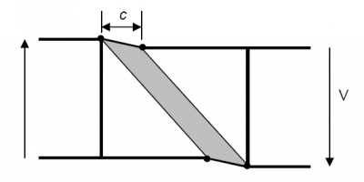
The contribution to shear resistance from the flange depends on the plastic resistance of the flange plate bending out of its plane. The mechanism for this flange contribution to elastic shear is illustrated below and depends on the presence of reasonably close transverse stiffeners supporting the flange plate against bending.
The EN 1993-1-5[3] expression for the flange contribution to elastic shear resistance is given below and stems from a consideration of the energy involved in the flange collapse mechanism illustrated below:

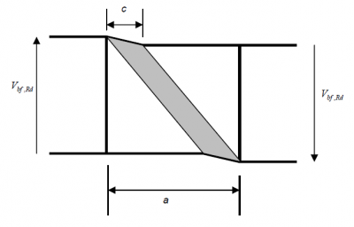

It can be seen that the flange contribution includes an interaction with the design bending moment, which is taken as a proportion of the moment resistance of the flanges alone, Mf,Rd. It should be noted that this moment resistance needs to be reduced if axial force is present. The flange dimensions in the above expressions should be taken for the flange that provides the least axial resistance and the effective width of the flange, bf, should be taken as zero if the flange is on one side of the web only.
The contribution to shear resistance from the flange is often very small and can always be conservatively ignored to avoid the additional calculation effort.
[top]Combined bending and shear
The resistance values discussed above relate to the separate values for bending and shear. These effects however, coexist and consequently their interaction must be considered.
The rules for the interaction of bending and shear stem from the results of extensive testing into the phenomenon. The results are a series of interaction checks which are best considered graphically as illustrated below. The structural significance of each region of such shear-moment interaction diagrams can be readily identified and it is frequently useful for the designer to plot the interaction curve in performing his calculations as it provides a comprehensible indication of the efficiency of the section.
The interaction between shear and bending depends on the class of the section and whether or not the section is susceptible to shear buckling. The interaction limits for steel sections in Eurocode 3 are based on plastic shear resistances even for Class 3 and 4 sections. This is justified by tests that show that little moment shear interaction actually occurs in practice. The limits for composite sections are discussed below.
[top]Steel section not susceptible to shear buckling
Class 1 & 2 sections
For Class 1 and 2 sections, testing has shown that, even for relatively high values of shear force, the reduction due to shear on the plastic moment resistance is negligible. This can be explained by the strain hardening of the steel. Thus EN 1993-1-1[1] allows the interaction between shear and bending to be ignored when the design shear force is less than 50% of the plastic shear resistance. Where the design shear force is greater than 50% of the plastic shear resistance, the shear is taken into account by using a reduced web yield strength of (1 − ρ)fy in the calculation of plastic resistance moment, where

where VEd is the design shear force and Vpl,Rd is the plastic shear resistance.
As an alternative to reducing the web strength, the thickness of the web could be reduced by the same factor but this reduced web thickness should not of course be used to re-classify the web as a higher class for direct stresses. EN 1993-1-1[1] gives a formula for equal flanges I-beams, but steel sections in bridges rarely have equal flanges in high shear regions and this is therefore of little practical use.
The shear-moment interaction envelope for Class 1 and 2 sections not susceptible to shear buckling is shown below.
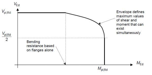

The resistance moment of the flanges alone Mf,Rd is given simply by the axial resistance of the smaller flange multiplied by the distance between flange centroids.
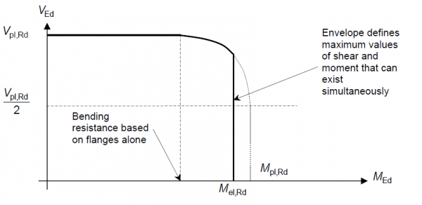
Class 3 & 4 sections
For Class 3 and 4 sections sections that are not susceptible to shear buckling, the shear-moment interaction envelope is essentially the same as for Class 1 and 2 sections discussed above, but the moment is limited to the elastic resistance moment Mel,Rd as indicated below and the curved portion is very slightly lower because the contribution from the reduced web is taken elastically although the difference is very small.

[top]Steel section susceptible to shear buckling
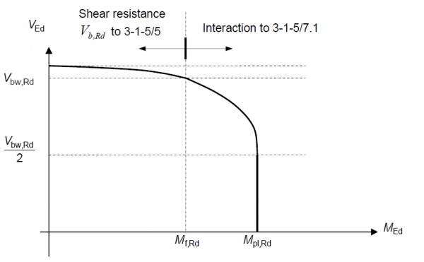
Now consider the shear-moment interaction for a section that is susceptible to shear buckling. The approach is similar to that for no shear buckling where interaction between bending moment and shear can be ignored if the design shear force is less than 50% of the shear buckling resistance based on the web contribution alone. Where the design shear force exceeds this value, the following interaction limit applies, irrespective of section class:

Class 1 & 2 sections
Thus the shear-moment interaction diagram for Class 1 and 2 sections susceptible to shear buckling is shown below.

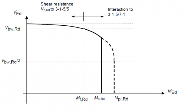
Class 3 & 4 sections
For Class 3 and 4 sections, the moment is again limited to the elastic resistance moment Mel,Rd. This effectively truncates the shear-moment interaction diagram as indicated below.
For Class 4 sections, Mpl,Rd, Mel,Rd and Mf,Rd should be based on the appropriate reduced flange areas. The gross web area however can be used in the calculation of Mpl,Rd. This use of plastic properties for the shear-moment interaction is again valid on the absence of any significant interaction evident in the tests on beams with Class 4 webs.
The bearing stiffener at a support will prevent the web buckling, so EN 1993-1-5[3] allows the interaction in this region to be verified at a distance hw/2 from the support using ![]() . However, the shear resistance of the cross-section still needs to be verified at the support, so it is recommended[4] that the support cross section is verified using the same interaction equation but with
. However, the shear resistance of the cross-section still needs to be verified at the support, so it is recommended[4] that the support cross section is verified using the same interaction equation but with ![]() , i.e. the plastic shear resistance is used in place of the shear buckling resistance.
, i.e. the plastic shear resistance is used in place of the shear buckling resistance.

[top]Buckling resistance of steel beams
EN 1993-1-1[1] provides rules for the determination of flexural buckling resistance and of lateral torsional buckling resistance (LTB) but for composite bridges usually only the resistance to LTB needs to be considered.
[top]Introduction to lateral torsional buckling


The full elastic and plastic bending resistances described above for different section classifications cover only part of the calculations necessary to determine the final flexural resistance of an element. This is because the flexural resistance of most bare steel beams in bridges is governed instability by due to lateral torsional buckling (LTB).
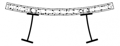
LTB is a mechanism involving gross lateral and torsional deformations as illustrated (in exaggeration) right, with no distortion of the cross-section. In composite bridges, this potential response is usually only seen before the slab is cast.
In the figure, both lateral and torsional movement can be observed at the centre of the beam. The tendency for LTB can therefore be reduced by bracing the compression flange against lateral movement or by torsional bracing to restrict rotation of the beam. Restriction of torsion is partially achieved when beams are braced together in pairs and twist can only take place in conjunction with vertical displacement of each beam. Such bracing is often provided during construction prior to the addition of a decking system. It is also necessary to consider the stability of the braced pair of beams, however, as the overall system can still buckle laterally in the steel-only condition. Once the decking system is installed, LTB is rarely a problem.
Historically, BS 5400-3[6] provided the designer with extensive guidance on LTB, but this was largely empirical. Eurocodes 3 and 4 are highly theoretical in their coverage of buckling resistances and for all but the simplest situations this tends to lead the user to use finite element modelling or a simplified ‘strut model’ at the compression flange. For the case of LTB of paired bare steel beams, rules derived from those in BS 5400-3[6] are available as an alternative to buckling model.
[top]Resistance to lateral torsional buckling
In EN 1993-1-1[1], the elastic critical buckling moment Mcr is used as an important parameter. For an initially straight beam with equal flanges and bisymmetric cross section, the elastic critical moment to cause buckling into the shape shown above is conservatively given by:

where Iw is the warping constant of the section, Iz is the minor axis second moment of area, IT is the St. Venant torsional inertia and L is the length of the beam between points of restraint. The force at which a beam buckles depends on a large number of factors including:
- Section properties
- Distribution of moment between restraints
- Height of the loading above the shear centre
- Support conditions (resistance is enhanced if warping restraint is also present in addition to full torsional restraint, but resistance is reduced if the torsional restraint is not rigid)
- Stiffness and type of intermediate restraints
The calculation becomes very much more complicated for monosymmetric and asymmetric beams and is best performed using a computer analysis as discussed below.
The design buckling resistance of a member is given in EN 1993-1-1[1] as:

where Wy is the plastic section modulus for Class 1 and 2 sections, the elastic section modulus for Class 3 sections and the elastic effective section modulus for sections in Class 3 and ![]() is the reduction factor for lateral torsional buckling and its value is given by a buckling curve, depending on the non-dimensional slenderness, which is
is the reduction factor for lateral torsional buckling and its value is given by a buckling curve, depending on the non-dimensional slenderness, which is ![]()
The form of the buckling resistance curves for lateral torsional buckling is the same as for flexural buckling and uses the familiar ‘Perry Robertson’ approach. Each curve has a plateau of unity for low slenderness and a curve, below the elastic buckling curve, that depends on an imperfection parameter. In EN 1993-1-1[1] five different curves are provided, as shown below; the length of the plateau is the same for the general LTB case as for flexural buckling and the choice of curve (value of imperfection factor) depends on a number of parameters including:
- Method of manufacture
- Shape of the section
- Axis of buckling
- Yield strength
For welded sections, the appropriate curve is either curve c or curve d for LTB (and curves b, c or d for flexural buckling of welded sections).
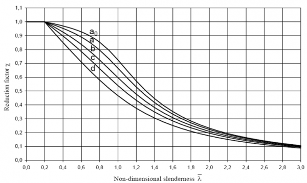

The curves are defined by the following expression:

The values of the imperfection factors, αLT, for each curve are given below.
| Buckling curve | a0 | a | b | c | d |
| Imperfection factor, αLT | 0.13 | 0.21 | 0.34 | 0.49 | 0.76 |
The non-dimensional slenderness parameter ![]() depends on the appropriate section modulus for the class of section as discussed above, as well as the elastic critical moment, Mcr. Note that the calculation of Mcr should always be made on the gross cross section because the loss of strength due to local plate buckling is much more severe than the loss of stiffness it causes. It would therefore be too conservative to consider a reduction to Mcr in the slenderness calculation.
The designer thus needs to calculate Mcr or slenderness from one of the following methods:
depends on the appropriate section modulus for the class of section as discussed above, as well as the elastic critical moment, Mcr. Note that the calculation of Mcr should always be made on the gross cross section because the loss of strength due to local plate buckling is much more severe than the loss of stiffness it causes. It would therefore be too conservative to consider a reduction to Mcr in the slenderness calculation.
The designer thus needs to calculate Mcr or slenderness from one of the following methods:
- Text book solution
- Computer elastic critical buckling analysis
- Empirical means
- Simplified compression flange model.
Elastic critical buckling moment from text book solution
Obtaining the elastic critical buckling moment from first principles as a text book solution is not very practical for bridge design and is not considered further here.
Elastic critical buckling moment from computer analysis
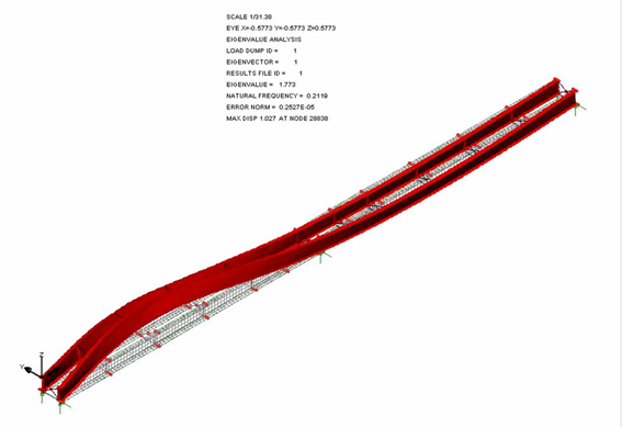
It is becoming increasingly easy to calculate Mcr directly from a computer elastic critical buckling analysis, using a shell finite element model, and many engineers will find this the quickest and most accurate method. Some experience is required however to determine Mcr from the output as often the first buckling mode observed does not correspond to the required global buckling mode; there may be many local plate buckling modes for the web and flanges before the first global mode is found.
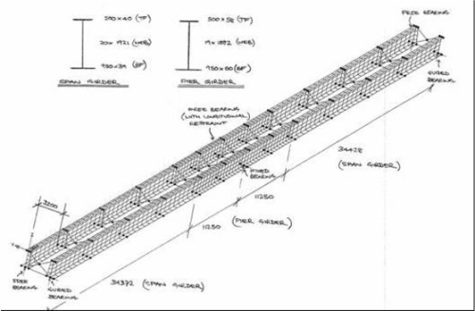
The figure below illustrates an example general arrangement of a finite element model for the analysis of a typical pair of girders during construction in two-span bridge. Such a model typically comprises:
- Thick shell elements for webs and flanges
- Thick shell elements for the transverse stiffeners
- Beam elements for bracing members.

The Figure below illustrates the first global mode shape of the elastic critical moment for this example obtained from a finite element shell model.

Having obtained the elastic critical buckling moment in this manner, the non-dimensional slenderness can be determined from the square root of the ratio of the characteristic resistance moment to Mcr, thus:

The buckling resistance moment is then given by the reduction factor in the usual manner as explained above.
Elastic critical buckling moment from empirical expressions
The empirical rules for determining slenderness for the ‘flexible torsional restraints’ case formerly in BS 5400-3[6] are available, in Eurocode format, in SCI P356 and PD 6695-2[7]; these can be used for relatively uniform situations and should give conservative results.
Elastic critical buckling moment from simplified strut model
It is also possible to determine the LTB slenderness by considering the flexural slenderness of the compression zone (comprising the compression flange and part of the web). This method is of particular assistance for the composite stage and is discussed under that heading below.
Further guidance on how to determine the buckling resistance of steel plate girders in composite bridges during construction (the bare steel stage) and in service (when the deck slab acts as a top flange) is available in ED008
[top]Cross section resistance of composite beams
[top]Classification of cross section
The same classification of cross sections as used for steel beams applies, since the classification depends on the buckling of the steel plate elements.
The top flange is connected to the slab by shear connectors and this connection can improve the classification of a thin flange, provided that the shear connectors are sufficiently closely spaced.
[top]Bending resistance of composite beams
[top]Plastic bending resistance
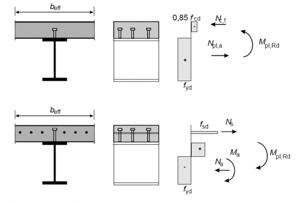
The above resistances from Eurocode 3 for steel beams are extended in Eurocode 4 to include composite sections in either hogging or sagging bending. To determine the plastic bending resistance of composite sections, the following assumptions are made:
- Full interaction between steel, reinforcement and concrete – this is normal practice for bridge design and assumes no slip between the composite components
- The effective area of the structural steel member is stressed to fyd
- The effective area of reinforcement in tension is stressed to fsd; the area of reinforcement in compression is ignored
- The effective area of concrete in compression is stressed to 0.85fcd
These assumptions are illustrated below. In all the above, the subscript “d” is taken to be the design strength (characteristic strength divided by the appropriate partial factor on strength). Particular care must be taken for the concrete stress block distribution however, as the definition of fcd unfortunately differs between Eurocode 2 and Eurocode 4. In Eurocode 4, fcd = fck /γc and the rectangular stress block extends down to neutral axis. In Eurocode 2, the effective area is stressed to fcd, but fcd = αcc fck/γc and the rectangular stress block extends over only 80% of compression zone. The scope for additional error arises as the recommended value of αcc in this equation is 0.85. This is particularly problematic when verifying the deck slab for local plus global effects as the Eurocode 2 definition will be applied for the reinforced concrete slab only and the Eurocode 4 definition for the composite section.

[top]Elastic bending resistance
For asymmetric sections (i.e. all composite sections) as well as Class 3 or 4 sections, it is also important to consider the elastic bending resistance to ensure that working stresses at Servicability Limit State (SLS), under the characteristic combination of actions, do not induce permanent deformations. To determine the elastic bending resistance of composite sections, it is assumed that the design resistance of the section is attained when any one of the following limits is reached:
- The stress of any concrete fibre in compression reaches fcd
- The stress in any structural steel fibre reaches fyd
- The stress in any reinforcement in tension reaches fsd (stress in reinforcement in compression is again ignored)
The stresses for verification against the above limits need to be taken from the summation of the stresses in each component from the different construction stages (steel only models for steel self weight and wet or precast concrete self weights, long-term composite models for other permanent actions and short-term composite models for transient loads). An appropriate modular ratio must be used for the composite models and for long-term actions, this must allow for creep of the concrete deck. This is covered in more detail in the pages on structural modelling and analysis. A schematic illustration of the summation of these stresses is shown below where Ma,Ed represents the design moment at a section applied to the steel beam alone and Mc,Ed represents the subsequent design moment at the same section applied to the composite section. Note that the Mc,Ed moments applied to the composite section need to account for appropriate long-term or short term concrete properties. This is covered further in the pages on modelling.
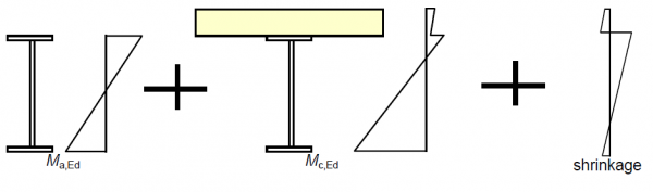

Un-propped construction normally proceeds by stages, which may often be considered individually in bridge design. Whilst the sequence of erection of the beams is often known at the design stage, the concrete pour sequence is rarely known. Typically, either a range of possible pour sequences is considered or it is assumed that the whole of the wet concrete is placed simultaneously on the bare steelwork, and the resulting design is re-checked when the pour sequence is known. The weight of formwork is, in reality, applied to the steel structure and removed from the composite structure (unless precast panels are used). Theoretically, this process leaves self-equilibrated residual stresses in composite cross-sections. Whether or not this is considered in the final situation is a matter for judgement, depending on the significance of the weight of the formwork. For Class 3 and 4 sections, the self-equilibrating stresses from differential shrinkage should also be included in the summation of stresses during construction stages, as indicated in the figure above.
As a consequence of the summation of effects, for un-propped construction, the total elastic resistance moment depends on the proportion of the effects on the steel beam and those on the composite beam (i.e. the relative proportions of Ma,Ed and Mc,Ed, although this simplification fails to distinguish between long-term and short-term effects) and can be calculated from:
![]()
where k is an arbitrarily chosen constant such that one of the above stress limits is reached at an extreme fibre. As for steel only sections, stresses may again be verified at the mid-plane of flanges rather than the extreme outer fibres. The total from the above equation is usually less than Mel,Rd when calculated for short-term composite section alone. The main uses of this calculation of Mel,Rd are for:
- Verification of resistance to lateral torsional buckling
- Calculation of longitudinal shear in bridges for plastic sections
For Class 4 sections, we have seen that the effective section needs to be calculated for the web widths (and /or, unusually, for the flange widths). For staged construction, there is the additional problem that the stress distribution changes during construction and therefore the size and location of the effective part of the element also change at each stage. To avoid the iteration and complexity associated with this, Eurocode 4 allows a simplification where the stress distribution at any stage is built up using gross section properties (but still accounting for shear lag). This final summed stress distribution is then used to determine the effective web width. The built-up stress distribution can then be re-calculated using the new effective cross-section, but with no need to iterate to modify the effective section. This simplification is illustrated below.


[top]Shear resistance of composite beams
For composite beams, it is usual to base the shear resistance on the steel beam alone. This is allowed in the Eurocodes unless “a contribution from the reinforced concrete part can be established”.
Shear buckling resistance of composite beams
The same three-stage shear failure mechanism is applicable for a composite section but the attachment of the slab to the top flangeenhances the restraint that that flange provides to the tensile band, as illustrated below.
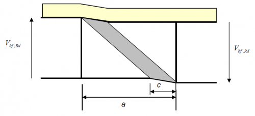

Consequently, the resistance provided by anchorage may be based on the bottom flange.
Note that there will be axial force on the steel section because of the tension in the slab, so the flange contribution will be affected. The contribution to the overall shear resistance of the concrete is small for deep composite plate girders typical of bridge members, but can be significant for shallower members where the slab is a significant proportion of the total deck depth. Note however, that the concrete deck slab is only indirectly considered in the calculations of tension field action, as only the bare steel flange is considered in calculating the tension field band length, c.
[top]Resistance of composite section to combined bending and shear
For composite sections, much of the above shear-moment interaction rules for steel only beams are still applicable. Additionally, for Class 3 and 4 sections, Eurocode 4 allows MEd to be taken as the total moment (from the summation of stages) rather than multiplying the total accumulated stress at an extreme fibre by the elastic modulus of the effective composite section.
[top]Interaction of bending, shear and axial force
The interaction of bending and shear for a section becomes more complicated with the presence of axial force. This can be significant in the design of steel and composite beams when used for integral bridges. EN 1993-1-1[1] gives interaction formulae for reducing the design plastic moment resistance due to axial force (for Class 1 and 2 sections) and stress criteria for combined bending and axial force (for Class 3 and 4 sections). These additional reductions and criteria should then considered in the interaction with shear force.
[top]Buckling resistance of composite section
The only regions of composite slab and beam bridges that are susceptible to buckling at the composite stage are the bottom flanges in the hogging regions of continuous composite beams where the top flange (in tension) is restrained by the concrete deck.
Then the buckling failure mode of the compression flanges requires the cross section to be distorted as shown below; this is often referred to as distortional buckling. A similar mode also seen in the sagging regions of half-through bridges and the buckling models for such situations were initially developed for half-through railway bridges.

[top]Resistance to distortional buckling
The evaluation of resistance to distortional buckling uses the same approach of non-dimensional slenderness and reduction factor as for LTB and the slenderness can be determined in a 3D buckling model but the simplified strut model approach will give satisfactory answers in most cases.


Elastic critical buckling moment using simplified compression flange model (strut model)
EN 1993-2[2], Clause 6.3.4.2(2) gives an alternative, simplified method for determining the elastic critical buckling moment ‘for lateral or lateral torsional buckling’ by considering a model of the compression chord of a truss or the compression flange of a beam alone. This method can be used for beams where the tension flange is held in position laterally. It considers the lateral buckling of the compression flange when restrained at intervals, either rigidly or flexibly; the method can also be used for the EN 1994-2[8] model of continuous flexible restraint.
The method is primarily intended for U-frame type bridges but can be used in hogging zones in steel and concrete composite construction. In this simplified method, the torsional inertia of the beam is ignored. This simplification may become significantly conservative for shallow rolled steel sections but is generally not over-conservative for most fabricated bridge girders.
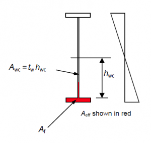
The simplified method allows the slenderness of a beam to be determined from an elastic critical buckling analysis of the compression chord alone. The compression flange (with an attached portion of web in compression) is modelled as a strut with an effective area Aeff. The strut is supported by springs in the lateral direction to represent restraint from bracings (including discrete U-frames) and from any continuous U-frame action as indicated in the figure below.
The elastic critical buckling load (Ncrit) for this strut model can then be determined by computer or by hand and the slenderness for LTB calculations determined based on the slenderness of the compression flange as a strut from:

This approximate definition of Aeff (greater than the flange area alone) is necessary to ensure that the critical stress produced for the strut is the same as that required to produce buckling in the beam under bending moment.

Values of spring stiffness, Cd, to be used in the simplified compression strut model are provided in Annex D of EN 1993-2[2]. They can be calculated from the following expression:

where the definitions of the key parameters are illustrated below.
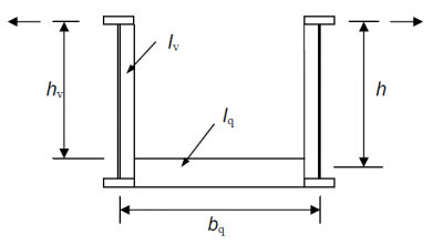

This case also covers inverted U-frames, such as in steel and concrete composite bridges when the cross member stiffness is based on the cracked inertia of the deck slab and reinforcement or the cracked composite section of a discrete composite cross girder. The formula can also be used to derive a stiffness for an un-stiffened web acting as the vertical member in a continuous U-frame, although generally, inclusion of this small restraint stiffness will have little effect in increasing the buckling resistance. Section properties for stiffeners should be derived using an attached width of web plate, as for stiffener design.
It should be noted that the above formula makes no allowance for flexibility of joints and that joint flexibility can significantly reduce the effectiveness of U-frames. Factors for joint flexibility, taken from BS 5400-3[6] , are available in PD 6695-2[7]
Where moment reverses along the length of a beam or for girders with variable sections, computer analysis is best to determine the elastic critical buckling of the simplified compression strut model. EN 1993-2[2] does give formulae that allow for the variation of moment along the beam, for:
- U-frame type decks
- Short lengths of beam between rigid restraints (typical composite beam in service).
Further guidance on the use of the simplified compression flange model to determine elastic critical buckling moments and worked examples for specific bridge applications are given in the Thomas Telford Guides to EN1993-2[4] and EN1994-2[9].
[top]References
- ↑ 1.00 1.01 1.02 1.03 1.04 1.05 1.06 1.07 1.08 1.09 1.10 BS EN 1993-1-1:2005+A1:2014, Eurocode 3: Design of steel structures. General rules and rules for buildings, BSI
- ↑ 2.0 2.1 2.2 2.3 BS EN 1993-2:2006. Eurocode 3: Design of steel structures. Steel bridges. BSI
- ↑ 3.0 3.1 3.2 3.3 3.4 3.5 3.6 3.7 3.8 BS EN 1993-1-5:2006+A2:2019. Eurocode 3: Design of steel structures. Plated structural elements. BSI
- ↑ 4.0 4.1 4.2 Designers Guide to BS EN 1993-2 Eurocode 3:Design of steel structures. Part 2 Steel bridges. Hendy, C.R.; Murphy, C.J. (2007). Thomas Telford Ltd.
- ↑ NA+A1:2016 to BS EN 1993-1-5:2006. UK National Annex to Eurocode 3: Design of steel structures. Plated structural elements. BSI
- ↑ 6.0 6.1 6.2 6.3 BS 5400-3:2000. Steel, concrete and composite bridges. Code of practice for design of steel bridges. BSI
- ↑ 7.0 7.1 PD 6695-2:2008+A1:2012. Recommendations for the design of bridges to BS EN 1993. BSI
- ↑ BS EN 1994-2:2005. Eurocode 4: Design of composite steel and concrete structures. General rules and rules for bridges. BSI
- ↑ Designers Guide to BS EN 1994-2 Eurocode 4: Design of composite steel and concrete structures. Part 2 General rules and rules for bridges. Hendy, C.R.; Johnson, R.P. (2006) Thomas Telford Ltd.
[top]Resources
- Iles D.C. (2010) Composite highway bridge design (P356 including corrigendum, 2014). SCI
- Iles D.C. (2010) Composite highway bridge design: Worked examples (P357 including corrigendum, 2014). SCI
- Iles D.C. (2012) Determining the buckling resistance of steel and composite bridge structures. (ED008). SCI
[top]See also
- Multi-girder composite bridges
- Ladder deck composite bridges
- Integral bridges
- Half-through bridges
- Material selection and product specification
- Modelling and analysis of beam bridges
- Shear connection in composite bridge beams
- Design for half-through construction
- Bracing systems
- Stiffeners