


Design for steel bridge construction
To ensure that a steel bridge design can be safely, economically and reliably executed (fabricated, assembled and erected), designers should be aware of the processes of fabrication and erection, the capabilities and limitations of the steelwork contractor and how the design choices affect those processes. This article provides guidance on design for construction: it generally follows the sequence of activities undertaken by the steelwork contractor.

(Image courtesy of Mabey Bridge Ltd.)
The objectives of ‘design for construction’ are:
- To maximize the efficiency of the construction process
- To minimize the need for clarification and change
Achieving these objectives will reduce costs, reduce the construction period, enhance quality and increase the safety of the work.
The activities for the steelwork contractor include planning, ordering, modelling, fabricating, assembling, coating and erecting.

(Image courtesy of Mabey Bridge Ltd.)

(Image courtesy of Mabey Bridge Ltd.)
[top]Planning
There are two basic approaches to design and construction:
- Traditional approach – the Designer makes the structural choices and the Steelwork Contractor builds to the drawings
- Early contractor involvement (ECI) – The Designer and Steelwork Contractor liaise at an early stage to optimize the construction process
[top]Traditional design
Under traditional arrangements, at concept stage and at detailed design stage, the designer of the permanent works produces a completed design that then passes, with an accompanying technical specification, and usually via a main contractor, onto the steelwork contractor. The designer assumes a particular method of erection and makes the decisions regarding an appropriate design solution for allowing the structure to be constructed safely, within programme and budget in accordance with that method.
For design to the Eurocodes, the technical requirements for the steelwork are described in BS EN 1090-2[1] and this refers to the “design basis method of erection”, the method that the designer has assumed in developing the design. Tenderers can put forward alternative construction methods (see GN 4.04), depending on the particular expertise or facilities that they can offer but whichever is the chosen method, the original or the alternative, the link between design and construction is at the heart of an efficient and economic solution.
[top]ECI – Early Contractor Involvement
Early Contractor Involvement is a form of contract in which the main contractor and the steelwork contractors are involved much earlier in the design process. Obviously, the significant advantage of this type of contract is that the designer is able to call on the advice of the ‘specialists’ to assist on the development of the most appropriate solution. This can offer benefits in:
- Development of the scheme
- Value Engineering
- Buildability
[top]Constraints

Shoreditch High Street bridge
(Image courtesy of Mabey Bridge Ltd.)
Each site has a different environment and infrastructure and each will present different constraints and opportunities for the designer to consider, before defining the structural form. The site can have a considerable influence on the structural form and how it can be erected. Particular factors include:
- Location of the structure
- Constraints of the site
- Access
- Phasing of the erection
- Availability and size of erection plant
- Requirements for rapid installation, e.g. during possession
- Working over or adjacent to water
Before the structural form is selected, it is important to check each option against the basic construction issues, and to compare practicable methods of delivering and erecting the bridge.
[top]Standard for execution of steelwork
The ‘reference standard’ in the Eurocodes for the execution of steelwork is BS EN 1090-2[1]. That standard is a comprehensive document with a range of options and alternatives, to suit the individual project; for UK bridges the Specification for Highway Works[2] will be appropriate for most highway bridge projects. For railway bridges, Network Rail's Specification for structural steelwork[3] is very similar.
Further information on the specification of bridge steelwork is available.
[top]CDM Regulations
The CDM regulations[4] require everyone involved in the project to identify hazards early on so that they can be eliminated or reduced at design stage. It is pointless to complete a design first and then try to address the risks associated with the design. By then, all decisions will have been made and any changes will cost time and money. Eliminating hazards from the design, so far is reasonably practicable, will remove the associated risk and is therefore the best option.
Getting the concept method of erection right at the commencement of the project is fundamental to the overall success of the project.
[top]Ordering
[top]Materials and components
The most economical way to procure plate and section is from the mills in sizes to suit the project. Stockholders charge much more per tonne and the use of stock sizes will require additional butt welds and more waste. It is important therefore that the provision of the information for material ordering is timed to suit the lead times required by the mills. The information that the steelwork contractor needs to prepare orders is as follows:
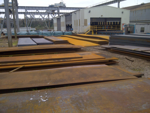

(Image courtesy of Mabey Bridge Ltd.)
Geometry
- Plan layout
- Levels at bearings
- Final profile of top flange
- Haunch definition (if any)
- Dead load precamber – total and breakdown
- Camber tolerance (if any)
- Web to flange weld sizes (for shrinkage and camber)
- Orientation of splices and girder ends
Make-up
- Plate and section dimensions
- bolts – quantity, type, diameter, plating
- Shear stud – quantity, length, diameter
Specification
- Steel grade for different thicknesses of plate and sections
- Restrictions on butt weld positions (if any)
- Options on geometric tolerances (see GN 5.03), surface quality, testing, CEV etc (if any)
Various items of additional information and options listed in BS EN 1090-2[1] Annex A should be provided by the designer, and guidance on this is given in the Specification for Highway Works[2]
[top]Bolt sizes
Splices should be designed using M24 preloaded bolts where possible because they are easier to tighten than M30 bolts and are more likely to be available from stock to replace losses or accommodate design changes. Non-standard sizes such as M22 and M27 should be avoided because suppliers do not keep them in stock.
[top]Shear stud sizes
Stud shear connectors suitable for bridgework are available in diameters of 19, 22 and 25 mm but steelwork contractors prefer 19 mm studs. All available sizes can be welded satisfactorily but as the size increases the level of weld defects and the wear on the welding equipment also increase.
[top]Geometry
The first key information that the steelwork contractor needs is the geometry of the fabricated shape and this information is usually conveyed on drawings. For a composite highway bridge the designer will specify the intended final geometry at completion but to determine the fabricated shape of the steelwork additional information is required giving the allowances for permanent deformation, for the assumed erection sequence (“design basis method of erection” according to BS EN 1090-2[1]). The information must also show clearly, which elements are intended to be truly vertical, which elements are curved and, in connections, which surfaces are to meet and align.
[top]Allowances for permanent deformation
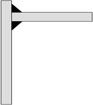
Permanent deformations arise as a result of shrinkage during fabrication, and of deflections due to the self weight of the structure, superimposed dead loads and shrinkage of the concrete deck. The steelwork contractor will calculate the allowances to be made for changes in shape during fabrication because they are under his control. The allowances for deflection of the structure and the final profile information however must be given on the drawings and are needed at an early stage for material ordering. The separate components for a simply-supported bridge are shown below.
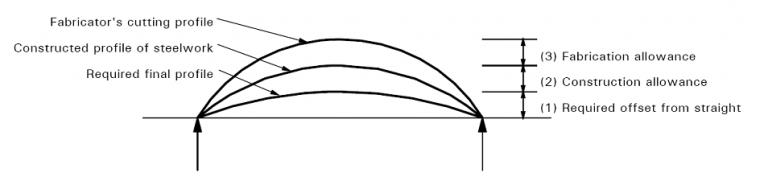

Notes:
- The required final profile is determined by the highway or railway engineer
- The construction allowance is calculated by the designer to allow for self weight deflection, pre-stress, concrete shrinkage etc. It should be split into steel self weight and other permanent loads so that the levels on completion of steelwork erection can be calculated.
- The fabrication allowance is determined by the steelwork contractor and can be in either direction, upward or downward depending on the details.
[top]Curvature in plan
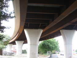

Hunslett Viaduct, Leeds
Plan curvature in girders can be easily accommodated by steelwork contractors. As well as being aesthetically more pleasing than using girders which are curved by a series of straight sections, girders which are curved in plan will simplify the construction of deck cantilevers along the length of the structure.
As with curvature in elevation, plan curvature should be defined by the designer using either clearly defined radii of curvature, or a series of co-ordinates.
In practice, a flange that is curved in its plane is formed, using numerically controlled cutting equipment, as a series of straight chords, usually no longer than 500 mm for radii up to 125 m, or no longer than 1000 mm for radii over 125 m. It is not usual for the designer to specify this.
[top]Bearing information

Some designers believe that, as bearings are typically available from manufacturers on an eight week lead time, they do not have to sort out the bearing requirements until eight weeks before the commencement of steel erection on site. The eight week bearing lead time is actually the manufacturing period for the bearing and if there are any special requirements on the project (e.g. uplift restraint), the bearing manufacturer will have to design the bearing and have design approval prior to this manufacturing period.
In addition, the steelwork contractor needs the tapered bearing plate details and orientation of bearings at the commencement of his fabrication process, i.e. the bearing information is required for the steelwork contractor much sooner than the bearing manufacturer.
The purpose of the bearing, and its orientation relative to the main steelwork members to which they are attached should also be clearly defined on the steelwork drawings to avoid errors during fabrication.
Guidance on how designers should calculate the movement range to be specified for bridge bearings, taking account of both thermal change and uncertainty in the relative positioning of bearings on the sub- and superstructures, is available in SCI P406.
[top]Timely and sufficient definition
The designer should provide sufficient information to enable the steelwork contractor to carry out a series of cross checks and so ensure that the information provided is accurate. For instance, it is advisable to show on the drawings both the basis of the final profile of the bridge and the levels at the supports. This allows the critical interface between steelwork and substructure to be independently verified.
Also, if the right level of information is provided on the steelwork drawings at an early stage, it will minimise the amount of ‘Requests For Information’ (RFI’s) which a steelwork contractor would need to raise to fully define the steelwork requirements. As well as minimising work for both the steelwork contractor and the designer, this will in turn reduce the time between the issue of the steelwork information and the commencement of the fabrication process. In order to plan and execute his work efficiently, the steelwork contractor needs all necessary information to be complete and agreed before he starts work, and this is reflected in the requirements of clause 4.1.1 of BS EN 1090-2[1].
[top]Modelling the structure
Once the steelwork requirements are fully defined, the information can be used by the steelwork contractor to create a two-dimensional or three-dimensional model of the steelwork using CADCAM software.
This software will create the list of components (girder webs and flanges, stiffeners, bracing members etc) required for the structure and produce the programs for each of the machines to be used in the fabrication process.
The model can also be used as a ‘virtual trial erection’ of the steelwork, allowing the steelwork contractor to look at the steelwork details from any angle. This is particularly useful when dealing with complicated details, for example, the ends of tied-arch bridges, as it enables the steelwork contractor to check the accessibility of the detail as part of design development prior to the commencement of fabrication.
CADCAM modelling
(Video courtesy of Mabey Bridge Ltd.)
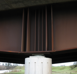
An example of the steelwork at the end of a large tied-arch bridge is shown below. This shows internal stiffening and bolted connections, as well as the flange and web plates.
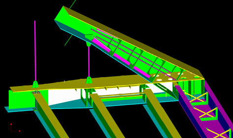

(Image courtesy of Mabey Bridge Ltd.)
[top]Fabricating the steelwork
The principal activities at the fabrication works are:
- Pre-assembly butt welding
- Cutting and profiling
- Drilling and edge preparation
- Assembly
- Welding
- Fitting of stiffeners
- Shear connectors
- Trial erection (rarely carried out)
- Coating application
[top]Pre-assembly butt welding
The steelwork contractor usually butt welds the flanges and web plates to full length in the shop before assembly of the girder. This means that such shop joints can be in different positions in the two flanges and do not have to line up with any shop joint in the web. If possible, the full width of plate supplied (from which several components will be cut) will be butt welded, as this will reduce the number of run-on/run-off plates and minimise butt weld testing requirements.
Pre-assembly butt welding
(Video courtesy of Mabey Bridge Ltd.)
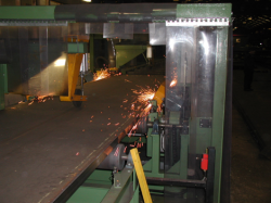
[top]Cutting & drilling
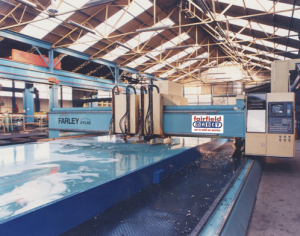

(Image courtesy of Mabey Bridge Ltd.)
Flame or plasma cutting equipment is used to cut flanges to length and width, webs to profile and camber, and stiffeners to shape. Plates up to 35 mm thick can be profiled using plasma cutting equipment. Plates greater than 35 mm thick will usually be cut using oxy-propane, which is safer than using oxy-acetylene.
In addition to the geometric requirements of plan curvature and precamber defined by the designer, the steelwork contractor will also take into account the allowances required for thermal cutting, and shrinkage such that the final girder geometry matches that required.
Some plate cutting machines also have the ability to mark stiffener positions on web and flange plates, and drill bolt holes for splice connections. Otherwise, the cut plates are hand marked and drilled later. See GN 5.06 for further information on thermal cutting of structural steels
Keeping bolt diameters and the resulting bolt hole diameters constant in a structure avoids potentially costly errors. Where additional tolerance is required in a bolted connection or rebar hole, it is easier and cheaper to specify a larger diameter hole rather than a slotted hole.
Plate preparation
(Video courtesy of Mabey Bridge Ltd.)
[top]Assembly
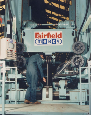

(Image courtesy of Mabey Bridge Ltd.)
The ability of a steelwork contractor to use his automated equipment to fabricate steelwork can greatly reduce fabrication costs and improve the quality of the finished product. This is probably most important in the assembly of flat plates into fabricated components.
On particularly complex fabrications, a designer is very unlikely to produce the most cost effective detail without the input of the steelwork contractor who will be carrying out the work. It is useful to bear in mind that different steelwork contractors have different equipment, and therefore different capabilities.
Some steelwork contractors have T & I machines which are used to assemble flat plates into ‘T’ sections and then ‘I’ sections. These machines will have limits on girder length, height, width, weight, curvature (in plan and elevation) and haunching which can be accommodated, which will differ between steelwork contractors. The larger machines can produce girders up to 4 m deep and 1.5 m wide. Welds can be built up in multiple passes through the machine but short lengths of built-up weld have to be done by hand.
As mentioned above, the more suited a structure is to automated assembly, the more cost-effective its fabrication will be. Designing beams as ‘I’ girders rather than box girders will make them more suited to automated assembly. Typically, an ‘I’ girder will involve 85% automated assembly, with only the stiffening being carried out manually (unless robot technology is used). An open top box will involve 70% automated assembly, with automated welds between the webs and the top flanges, welding of the stiffeners to the webs and bottom flanges to formed stiffened plates by robot, and with welding of the bottom flange to the webs being carried out manually. A closed top box will involve 35% automated profiling and marking of plates only, and all other fabrication (box assembly and stiffening) being carried out manually.
Automated section assembly
(Video courtesy of Mabey Bridge Ltd.)
[top]Welding
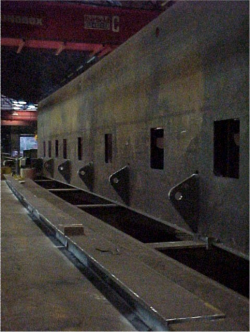
[top]Access for welding


(Image courtesy of Mabey Bridge Ltd.)
Wherever possible, girder stiffeners should be detailed to enable the steelwork contractor’s welding equipment to access the stiffener welds as required. This is a particular issue at support locations, where the close spacing of bearing and jacking stiffeners is necessary.
Generally, for robot welding, the clear distance between adjacent stiffeners should not be less than 400 mm or the width of the stiffener, whichever is the greater, taking account of the skew of any stiffeners.
The detailing of stiffener welds to main girder webs should also reflect the skew of the stiffener needed. These should always be specified as double sided fillet welds until the angle of the stiffener to the girder web is less than 30 degrees, at which point a single sided Full Strength Butt Weld (note – NOT a Full Penetration Butt Weld) should be specified.
Section stiffening
(Video courtesy of Mabey Bridge Ltd.)
[top]Weld type and size
It is tempting for designers to over-size welds for quickness of design, however a combination of large stiffener welds and thin girder webs can lead to a visible distortion of the web, more commonly known as the ‘hungry horse’ effect. Similarly, oversized welds at bearing stiffener ends can cause local distortions which make it difficult to provide a satisfactory surface for the bearing plates. Stiffener welds should therefore be designed and sized for their intended purpose, and no more. All welded joints should be detailed so that there is a landing length 5mm greater than the leg length of the weld. This will ensure a good quality weld whilst avoiding the need for unnecessary plate edge preparation.


(Image courtesy of Mabey Bridge Ltd.)
[top]Cope holes in stiffeners

A34/M4 Junction 13, Chieveley
When detailing stiffeners, the designer should consider how best to deal with the girder web to flange welds.
Traditionally, a cope detail would be used to ensure that the stiffener is clear of the girder weld; however, this leads to difficulty in getting sufficient protective treatment inside the cope hole. This problem is even worse for the maintenance of these details throughout the life of the structure. For painted bridges, this can be avoided by the use of a ‘sniped’ stiffener which is close fitted over the girder web to flange weld; the stiffener weld is then passed over the girder weld to form a ‘weld on weld’ detail with no limited areas of access for protective treatment.
For weathering steel bridges, however, there is no protective treatment system, but there is a need to provide sufficient drainage, so a stiffener with a 50 mm radius cope hole is preferable at the bottom flange location where the drainage is required. Sniped corners (45° cut across the internal corner) should be avoided in weathering steel bridges because the access is worse than a cope hole and the acute angle can give rise to cracking of the weld.
[top]Weathering steel components

(Image courtesy of Mabey Bridge Ltd.)
Rolled sections in weathering steel are less readily available in the UK than ordinary structural steel sections. This is particularly true for small quantities. As such, designers are strongly advised to confirm the availability of the required weathering steel rolled sections with the manufacturer at an early stage.
The potential lack of availability of rolled sections in weathering steel means that secondary bracing members may need to be designed as flat plates welded into the section required, in lieu of rolled angles or channels. These need to be detailed so that each weld has a suitable landing detail.
Weathering grade preloaded bolts used in bridge construction are generally available in the UK (in M24 size), but there can be situations where they are imported from North America (in imperial sizes, i.e. 1"), so they should be designed as M24 size but the bolt spacings should be such that 1" bolts can be substituted.
[top]Grinding of butt weld caps
Many clients believe that a butt weld becomes invisible when the capping runs are ground flush with the parent metal. This is not the truth in practice; grinding flush butt welds only serves to spread the ground area over a larger area adjacent to the weld, and this is clearly visible, even on a painted structure. Once they have had the opportunity of witnessing the appearance of a ground flush butt weld, most clients agree it is aesthetically better to ‘dress’ such butts (i.e. to remove weld spatter etc.) than to grind the butt weld flush. See GN 5.02 for guidance on post-weld dressing.
From a design point of view, a ground flush butt weld is a better fatigue detail than a butt weld which has not been ground flush; however, the common presence of nearby stiffeners usually makes this irrelevant.
Notwithstanding the above, welds to the top surface of main girder top flanges will need to be ground flush to facilitate seating of permanent and cantilever formwork, also welds to the top surface of main girder bottom flanges on weathering steel bridges need to be completely ground flush to facilitate run-off of rain water.
[top]Stiffeners and bracing
[top]Web stiffeners
A typical arrangement for a simple single intermediate web stiffener is a flat plate welded onto one face of the web and connected to one flange, usually the top flange. Flat stiffeners are preferred as they are easily welded onto web and flange plates using all-round fillet welds. They are normally attached after the web has been joined to the flanges.
Stiffening is a relatively expensive operation, and intermediate stiffeners should only be provided where necessary to attach intermediate bracing members to the girders.
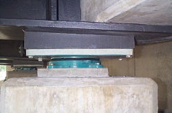
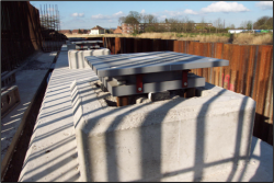
[top]Bearing stiffeners

(Also shows jacking stiffeners and web stiffneres at a change in bottom flange direction)
River Eden Bridge, Temple Sowerby Bypass
The webs of plate girders and rolled beams are normally designed with transverse load-bearing stiffeners at each support position. The usual arrangement is for the bridge girder to be placed with the bottom flange seated on top of the bearing and the stiffeners concentrically above the bearing. A tapered bearing plate is almost always required between the upper surface of the bearing and the underside of the flange so that the bearing remains horizontal.
The ends of a bearing stiffener need to be adequately connected to both flanges and it is usual for the stiffener to be ‘closely fitted’ to the flange subject to concentrated load. This is almost always the bottom flange. The end of the bearing stiffener will need to be ground to ensure that this requirement is achieved.
Bearing stiffeners should be wide enough to control the squareness of the main girders at support positions. On heavily skewed bridges, additional stiffeners adjacent to the bearing stiffeners may also need to be provided to control the squareness of the girders.
Bearing and jacking stiffeners should be specified as being ‘fitted’ to the top surface of the bottom flange of the member to which they are connected. Due to tolerances in plate flatness and girder squareness which are achievable, it is not practical to specify a bearing level of fit-up to both flanges.
[top]Detailing for assembly
The assembly of steelwork can have a considerable influence on the detailing of steelwork. For example, bolts should not be positioned within 100 mm of the face of a girder web or stiffener to enable them to be tightened using standard equipment. Special consideration should also be given when attaching bracing members to skewed stiffeners, as access for tightening equipment to the back of the stiffener will be limited.
[top]Web and stiffener verticality
Designers should specify that girder webs are to be vertical at the supports upon erection of the steelwork (see GN 7.03). There will often be transverse rotations of the steel girders, particularly in skew bridges, so it is necessary to state at which stage they are vertical. The actual rotations due to permanent actions are sometimes small in practice because of restraint from the formwork, the bracing and the vibrated concrete but it is impossible to predict what will happen.
The secondary forces produced if the webs rotated as predicted would normally be small and resisted by the bracing / diaphragm at the support. The design should allow for these forces.
Stiffeners should be square to the flanges if possible, rather than vertical. When stiffeners are cut out initially, the edges are cut square, so if the ends meet the flange at an angle they usually have to be bevelled to limit the weld gap. Bearing stiffeners are usually set nominally vertical.
[top]Alignment of surfaces
At a change in flange thickness the step should be on the inside face so that the overall depth of the girder is constant. The web can easily be profiled to the shape of the step when it is cut from the plate, and a smooth outer face makes handling in automatic girder welding machines easier.
Where webs of different thickness are joined, the steps occur on both sides of the web, to keep the web central to the girder section.
[top]Joint gaps
The gap between main girders in bolted splices should not be specified as being less than 6mm to accommodate the tolerances in fabricated length of the main girders and in the position of bolt holes in the connection.
On ladder decks, the gap between the ends of cross girders and the main girders to which they are connected should not be specified as being less than 10 mm to accommodate the tolerances in cross girder length, the straightness of the main girders, the accuracy in the profiling of main girder stiffeners and the positioning of bolt holes.
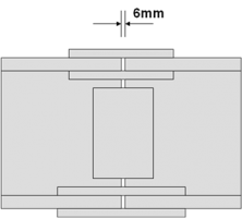
Joint gaps in main girder splices
(Image courtesy of Mabey Bridge Ltd.)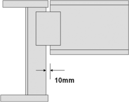
Joint gaps on ladder deck cross girders
(Image courtesy of Mabey Bridge Ltd.)


[top]Connections
Shop connections are almost invariably welded while most site connections are bolted for reasons given below. Splices should be positioned to suit transport limits and also a viable erection method. Attention should be given to ready access for welding, and space for installation and tightening of bolts using power tools.
[top]Bolting
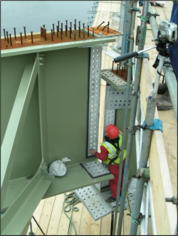

(Image courtesy of Mabey Bridge Ltd.)
Some clients do not like the appearance of bolted splices, but it should be remembered that bolted splices are relatively small. Generally, bolted splices are preferred for site connections as they are cheaper than welded connections, faster to install (as not all bolts need to be fitted during initial erection), less dependent on the weather, and temporary supports are seldom required. All blast cleaning is done in the steelwork contractors works - zinc plated bolts are used for short term protection to avoid blast cleaning before painting.
Nearly all bolted connections in UK bridgeworks are designed as slip resistant connections, using preloaded bolts traditionally referred to as high strength friction grip (HSFG) bolts. These enable forces to be transferred from member to member by friction generated between lapping parts of the joint. The performance depends on the condition of the surface of the interfaces.
Before final tightening and after bedding, the bolt group must be inspected to ensure that all interfaces are in contact. Then all bolts are fully tensioned using the chosen method. A variety of tightening methods are available:
The project specification should give the steelwork contractor the freedom to use the method of his choice. Most companies have a favourite method which they consider to be most economical and most reliable. Guidance on the installation of preloaded bolts is available in GN 7.05.
[top]Welding

(Image courtesy of Mabey Bridge Ltd.)
Welded splices give a cleaner line to the steelwork, but they are still visible, even if ground flush (as mentioned previously). However, welded splices are generally more expensive than bolted splices on site, take longer to complete, and introduce an element of programme risk from bad weather and/or the possible repair of defects.
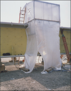
The process of making a welded splice requires temporary supports or landing cleats to support and align the girder until welding is complete, and a weatherproof tent around the splice. The welds are carried out in a planned sequence usually flanges first then webs. All welds are subject to inspection, usually requiring a 48 hour long period before testing. Upon completion, the welded splice region will require blast cleaning and the application of the coating system. For large projects with more than 500 connections, site welding may be more economical due to establishment costs. See GN 7.01 for further guidance on site welding.
Post-fabrication welded splice
(Video courtesy of Mabey Bridge Ltd.)
[top]Shear studs on cover plates
Shear studs on the cover plates of bolted splices can interfere with bolt tightening. This should be considered by the designer when detailing the bolted splices. The number of shear studs on cover plates should be kept to the minimum and located on the longitudinal centreline (as far as possible from the bolts). Shear studs should not be less than 75 mm apart, otherwise the welding gun used for shear stud connection will not have sufficient room. Shear stud spacing is limited to a maximum of 800 mm by BS EN 1994-2[5]


(Image courtesy of Mabey Bridge Ltd.)
[top]Cover plate thickness
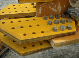

(Image courtesy of Mabey Bridge Ltd.)
Cover plates which are greater than 30 mm thick can become too stiff to enable preloaded bolts in the splice connection to bed down properly. Where splice cover plates greater than 30 mm thick are required, the steelwork contractor will often propose a combination of thinner plates that are flexible enough to cope with small ripples, angular changes and steps.
[top]Pack plate thickness and material
Pack plates are available in thicknesses down to 1 mm. In splices where the difference in thickness between connecting members is less than 2mm, packing plates should not be required.
Pack thickness
Where plate thicknesses at a joint change by 2 or 3mm, as they commonly do in girder webs, a 1mm pack is required on each face to avoid offsetting the webs and consequently increasing the risk of having problems installing bolts in the flanges. A minimum pack thickness of 1mm is now permitted in BS EN 1090-2[1] covering both preloaded and non-preloaded joints.
Pack material
Clause 8.1 of BS EN 1090-2[1] states that “Packing plates shall have compatible … mechanical strength with the adjacent plate components of the connection”. In this case, “compatible” should not be interpreted as “similar” because it is not always possible to obtain small quantities of thin material for packs in preloaded joints in grades that are the same as the members being joined. For packs less than 7mm thick, carbon steel can only be bought in grades such as DC01 to BS EN 10130[6] that has no guaranteed mechanical properties, and weathering steel shims are only available in “Corten A” that has lower yield strength and UTS than S355W to BS EN 10025-5 [7] and no toughness guarantee. In practice the compressive stress due to the preload and the shear stress from the slip resistance are much lower than the lowest possible yield stress for steel material, and there is no risk of brittle fracture, so these alternative materials are acceptable for use as packing in preloaded joints.
[top]Enclosed spaces

(Image courtesy of Mabey Bridge Ltd.)
Under current CDM legislation[4], work within ‘confined spaces’ must be avoided wherever it is cost-effective to do so. ‘Open top’ box girders produce such a confined space once the deck slab has been constructed, and maintenance of the internal protective treatment system will become an issue to the client. Closed box girders produce a confined space once the closing plate of the box girder section has been placed during assembly. Such boxes therefore also become an issue to the steelwork contractor during fabrication and during any initial internal painting.
All internal painting can be cost-effectively avoided by the use of weathering steel. The additional steel costs are not completely offset by the avoidance of internal painting but the premium is small, especially when the costs and risks associated with the maintenance of the internal system are taken into account.
Fabrication work inside the box also needs to be minimised as much as possible. The designer can contribute to this by detailing the corner welds for the closing plate in the box girder section as external welds, and by designing the box girder so that welded connections between any internal stiffeners and the closing plate are not required.
Where this is not possible, a safe system of work needs to be set up for the box girder fabrication. In addition to sufficient fume extraction, this will often entail access holes being cut into the box girder web adjacent to any butt welds or internal stiffeners, which can be closed after fabrication has been completed using infill panels which are butt welded to the girder web using single sided external butt welds to internal backing flats.
All of the above will add considerable cost to any box girder fabrication.
[top]Protective treatment
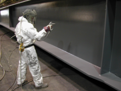

(Image courtesy of Mabey Bridge Ltd.)
Protective treatment is usually carried out after all the fabrication activities have been completed but before any bolted components have been assembled. As well as the specification of what is to be protected, information must be clearly given about which surfaces are not to be protected at this stage.
Protective treatment
(Video courtesy of Mabey Bridge Ltd.)
[top]Access for painting
Designers should consider the access required to apply protective treatment to all areas of exposed steelwork where required. This can often be an issue at the ends of skewed bridges, where a combination of skewed bearing / bracing stiffeners and square end plates / jacking stiffeners can produce semi-enclosed steelwork which is difficult to access for painting.
[top]Stiffener end protection
Where intermediate stiffeners are curtailed clear of the main girder bottom flange, the limiting length between the underside of the stiffener and the bottom flange required by BS EN 1993-1-5[8] is insufficient to enable the protective treatment to be adequately applied to the ends, if the stiffener is cut square. Cutting the end of the stiffener at a 45° angle will avoid this problem.
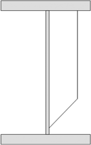
A typical web stiffener
(Image courtesy of Mabey Bridge Ltd.)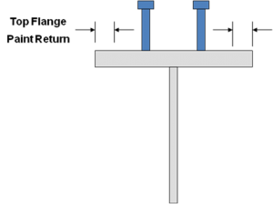
Top flange paint return
(Image courtesy of Mabey Bridge Ltd.)


[top]Top flange paint return
The return of protective treatment along the edges of the main girder top flanges should not extend beyond the outer face of the shear studs. Otherwise the paint has to be applied by brush because it cannot be sprayed without the risk of some studs being painted. The designer needs to bear this in mind when detailing his formwork seating arrangements and his shear stud layout.
[top]Edge grinding

(Image courtesy of Mabey Bridge Ltd.)
Historically, the edges of exposed plates were specified as being rounded to a 3mm radius. However, with the use of modern Epoxy protective treatment systems with chemical curing processes (older Acrylated Rubber systems relied on an evaporative curing process), which can be applied in thicker single coats it is generally considered sufficient to round edges to a 2mm radius. This has been recognised by Highways England in their Specification for Highway Works[2].
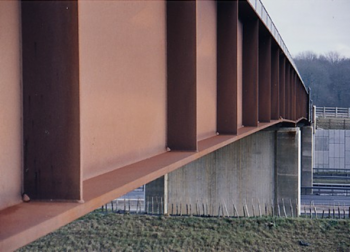
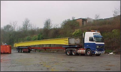
[top]Transportation
To maximise the amount of work carried out within the fabrication works, thus achieving the highest quality, the steel structure is fabricated in pieces as large as can reasonably be transported to site. The designer should anticipate how the structure will be split into separate components for delivery to site, particularly in considering member sizes and splice positions. The limitations relating to the transportation of fabricated items by road within the UK are summarised below:
| Load type | Maximum Vehicle dimensions | Notice required | |||
|---|---|---|---|---|---|
| Rigid length | Width | Weight | Police | HA | |
| Normal | 18.65 m | 2.9 m | 44 tonnes | None | None |
| Abnormal | 27.4 m | 5.0 m | 44 tonnes | 2 days | None |
| 18.65 m | 2.9 m | 80 tonnes | None | 2 days | |
| 30 m | 5.0 m | 80 tonnes | 2 days | 2 days | |
| 30 m | 5.0 m | 150 tonnes | 2 days | 5 days | |
| 30 m | 6.1 m | 150 tonnes | 2 days | 10 days | |
| Special order | > 30 m | > 6.1 m | > 150 tonnes | 5 days | 10 weeks |

(Image courtesy of Mabey Bridge Ltd.)
The limitations given are subject to change and local restrictions may apply, therefore the above table should only be used as guidance. Refer to GN 7.06 for further advice.
The limits set by Highways England relate to movement of loads on major roads, and do not take account of physical restrictions, such as street furniture, tight bends and hump back bridges that exist near to the fabrication works or adjacent to the bridge site.
Access to the site and positioning of the erection plant has to be planned and sequenced to ensure that disruption to adjacent services / infrastructure is minimised. Access onto site has to be coordinated with the traffic management scheme to ensure that craneage and steelwork can be brought onto site and mobilised with minimum disruption.
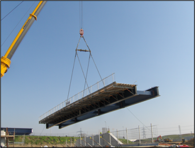
The 35 m long haunched girders illustrated here were delivered to site as a braced pair, for a single span integral bridge. The ability to transport the girders full length avoided the need to design site splices and the need for space on site to assemble girders into long lengths or into pairs.
[top]Bridge erection
How the bridge is designed and how it is built are linked. Ensuring that this link is recognised will have an effect on the safety and quality of the construction. Methods of erecting steel bridge structures vary considerably from site to site and from project to project. The subject of erection aspects is therefore a wide and varied subject. This section focuses on the aspects that should be considered during the initial design and detailed design phases.
Further information is available in the Guide to the Erection of Steel Bridges.
[top]Installation of bearings

(Image courtesy of Mabey Bridge Ltd.)
The first pieces of steelwork to be erected on site are the bridge bearings. The function of a bearing is to transfer weight of the superstructure to the substructure. They may also transfer transverse and longitudinal forces. They carry large forces but can be easily damaged by inappropriate handling or installation. Manufacturers supply bearings as complete units held together by transit bolts which are primarily for transportation and installation. Once the bearing is in place and the girder is landed, it is essential that the cleats are released in order to allow the steelwork to ‘breathe’ in a controlled manner.
Bearings can be supplied attached to the girders but it is more common for them to be aligned and levelled on the substructure and attached to the girders afterwards. The designer needs to give clear instructions about line, level and setting of bearings to ensure that they function as intended in service. Bearings are either bolted to a taper plate (in tapped holes) or through the taper plate and flange, however this last one is not preferred as it uncouples the late provision of bearing information from the fabrication of the girders. Because it is now a general requirement that bridge bearings must be designed to be replaceable, the attachment details must be chosen to facilitate replacement.
The designer must allow for safe access for precise installation of bearings. The means of access may need to be retained for maintenance and replacement of bearings.
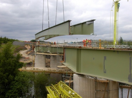
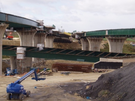
[top]Erection using cranes
Erection using cranes is considered the most cost effective erection method for the majority of structures. However, note that only crawler cranes and some small rough terrain mobile cranes are able to traverse the site with a load. The site areas adjacent to the bridge will affect the position and size of crane that can be used and this will affect capacity of lift and therefore choice of crane and the piece size. The area for preassembly will also influence lift size.
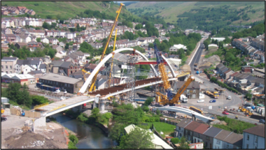
Erection of Porth Bridge using mobile cranes
(Image courtesy of Mabey Bridge Ltd.)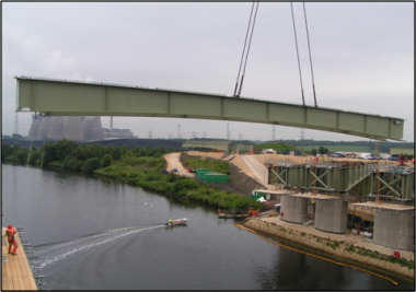
Lagentium Viaduct, A1(M) Darrington to Dishforth
(Image courtesy of Mabey Bridge Ltd.)


The compact and busy site (above left) shows the construction of a bridge crossing a river, railway and a road; the bridge is close to adjacent buildings. A tied-arch was chosen for the main bridge and a ladder deck for the river span. This choice allowed the decks to be erected piece-small onto temporary trestles and the arch to be erected later. Due the available area for preassembly and positioning cranes, each arch was erected as three separate pieces, with a maximum weight of 102t at 35 m radius, using a 1000 t crane with 200 t superlift.
The main river span of the Darrington-Dishforth link (above right) required the lifting of 50m long paired girders at a large radius. Each girder pair was lifted by cleats attached to the top flanges. The girders had to be checked for this high local tensile force and for stability under hogging bending in its midspan regions. The temporary works engineer will usually position the lifting cleats and check the stability of the girders during lifting operations. The permanent works designer is not normally required to look at this temporary condition.
Click here to see Mallard Bridge on White Rose Way, Doncaster being installed over the East Coast Main Line using one of the largest mobile cranes in the UK.
[top]Specialist transport
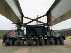

(Image courtesy of Mabey Bridge Ltd.)
Where lifting into position is not suitable, for example when there is a lack of space for a crane or there are overhead cables in the vicinity, one option is to assemble steelwork at low level away from (but close to) the actual bridge site. The assembled steelwork is then jacked up to allow specialist transportation units beneath the deck. The units are then used to transport the deck into position.
Transportation is most suitable where the whole bridge can be transported as a unit. It can thus be preassembled on temporary supports that do not impose high local forces or lock in stresses that depend on an erection sequence. Preassembly away from the site also allows the client to continue with the construction of the bridge piers and abutments for example without disrupting the assembly of the steel.
Click here to see Leigh Road Bridge being installed using specialist transporters in Slough.
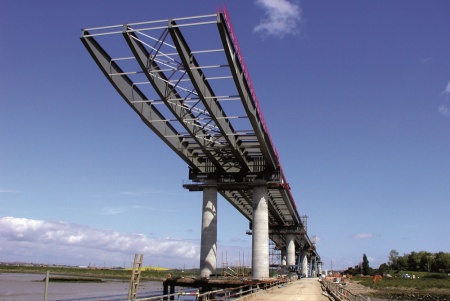
[top]Launching
Launching the steelwork over road or river, involves assembly of steelwork, typically behind an abutment, on the highway approach. The steelwork is assembled on low resistance rollers or a sliding system at each pier or temporary support. A haulage and restraint system is used. The steelwork requires plenty of construction alignment to ensure adequate fit up prior to launching and needs to have sufficient time in the programme to allow for this. However, assembly is normally near ground level, with the use of much smaller and less expensive cranes and minimum work at height.
Click here to see a 15 hour bridge slide in 70 seconds on the Loughor Viaduct Replacement scheme.
[top]Strand jacking
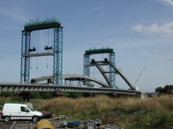

(Image courtesy of Mabey Bridge Ltd.)
Strand jacking is not commonly used as an erection technique as it is best suited to large lifts that cannot be carried out by crane. The temporary works for strand jacking are usually complex and expensive; the division of the structure into an erectable portion has to be influenced by the capabilities of the equipment.
Strand jacking is perhaps most commonly used for lifting long midspan river sections from a barge but it is suited to other cases such as the Usk River arch, shown left. The photo shows the arrangement for strand jacking the central portion of the arches of the 190 m span. The central portions of the arch were lifted onto the deck and transported into position beneath the jacking towers. The main lift was 640 tonnes. The arch members had to be designed for the locked-in bending stresses due to spanning between lift positions.
[top]Influence of erection durations
Erection durations are generally dictated by the client’s programme, the features of the site, and the principal contractor’s programme. Site erection durations control the balance between pre-assembly in the fabrication yard or on site adjacent to the proposed bridge, and the elements of the structure that can be erected directly off the transport.
[top]Erection on greenfield sites
Greenfield sites allow a free choice for erection methods and usually plenty of time. The steel superstructure can be erected directly off the transport and the elements spliced together in position. The amount of preassembly in this situation is dictated by the site programme advantage of pre-assembling the steelwork in the fabrication yard.The bridge below shows erection over a haul road, which meant that although access for cranes was free of constraint, temporary intermediate supports may not have been possible.
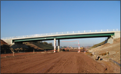

M6 Toll
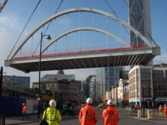
[top]Erection during possessions
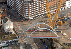

(Image courtesy of Mabey Bridge Ltd.)
The requirement to maintain traffic flow, whether road, rail or water, may severely limit the duration of erection operations. In such cases erection has to take place within a fixed or defined “possession” period.
Working within any form of possession, requires careful and precise planning. Often the cost penalty of over running can be extreme for both parties. If this is the case, it may be beneficial for most of the structure to be pre assembled prior to erection. Then the whole bridge can be lifted into place using a large crane positioned adjacent to the site.
The design needs to allow for as much assembly of construction as possible before erection, with only the minimal amount of location and fixing activities once the bridge is in position. In some cases deck construction can continue after erection but in others the deck has to be cast beforehand. The use of permanent formwork is very advantageous for erection under possession as it provides a safe working platform for the completion of the deck slab.
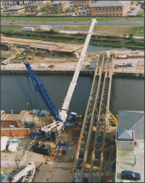
The tied-arch bridge shown here, which carries the East London Line Extension over Shoreditch High Street, was assembled behind one of the abutments and lifted in by crane during a 36 hour road possession. Permanent formwork and deck reinforcement were placed before lifting. The total weight was 353 t. Possession of the road was booked several months in advance.
[top]Stability during erection

(Image courtesy of Mabey Bridge Ltd.)
The efficient design of plate girders with a number of parallel steel plate girders using composite construction tends to produce small top flanges. This makes them prone to lateral torsional buckling during construction, before the slab has hardened. There is also a risk of instability during handling, delivery and exposure to high winds. Hence, designers should consider slenderness in the various erection conditions.
The most common way to improve stability is to assemble girders into braced pairs which makes them more stable during lifting and when in place compared to a single girder. The improved stability may also reduce the need for support trestles. As a consequence, site erection will be shorter, as a high percentage of bolting up and painting will have been completed prior to the structure being erected. However transport of braced pairs increases transportation costs.
Ideally, designers should make use of any temporary bracing for performance in service and thus make it permanent. Generally, making bracing permanent is more economic and avoids hazards of its removal. The operation of temporary bracing removal is inherently hazardous due to the limited headroom, following casting of the deck. This makes it difficult to install a suitable means of lowering what are often considerably heavy pieces of steel. This hazard is further compounded if the bracings are located over a road or railway.
[top]Deck construction

(Image courtesy of Mabey Bridge Ltd.)
Pre assembly for composite construction can be used to fit critical falsework and formwork, temporary and permanent walkways and edge protection, before lifting the bridge section into place. The advantage of this is two-fold. The formwork can be fitted at low level, which is inherently safer, and it also eliminates this operation from the critical path. The formwork would otherwise be fitted after completion of the erection.
Falsework systems such as that shown above have been developed such that they can be attached and removed without any significant risk of damage to protective treatment (or contamination of the surface of weathering steel). This eliminates the need for subsequent surface treatment, saving time and costs.
[top]References
- ↑ 1.0 1.1 1.2 1.3 1.4 1.5 1.6 BS EN 1090-2:2018, Execution of steel structures and aluminium structures. Technical requirements for steel structures, BSI
- ↑ 2.0 2.1 2.2 Manual of Contract Documents for Highway Works (MCHW). Volume 1: Specification for Highway Works. Series 1800 Structural Steelwork. April 2021, TSO
- ↑ NR/L2/CIV/140/1800C Specification for structural steelwork, Network Rail, June 2016,
- ↑ 4.0 4.1 Construction (Design and Management) Regulations (CDM) 2015
- ↑ BS EN 1994-2:2005, Eurocode 4. Design of composite steel and concrete structures. General rules and rules for bridges. BSI.
- ↑ BS EN 10130:2006, Cold rolled low carbon steel flat products for cold forming. Technical delivery conditions, BSI
- ↑ BS EN 10025-5: 2019, Technical delivery conditions for structural steels with improved atmospheric corrosion resistance, BSI
- ↑ BS EN 1993-1-5:2006+A2:2019, Eurocode 3. Design of steel structures. Plated structural elements, BSI
[top]Resources
- Steel Bridges: A practical approach to design for efficient fabrication and construction, 2010, (Publication no. 51/10), BCSA,
- Chapter 4 Bolting
- Chapter 5 Welding
- Chapter 6 Accuracy
- Chapter 7 Costs
- Chapter 8 Case studies
- Hendy, C.R.; Iles, D.C. (2015) Steel Bridge Group: Guidance Notes on best practice in steel bridge construction (6th Issue). (P185). SCI
- Guidance Note 4.02 Weld procedure tests
- Guidance Note 4.04 Consideration of alternative construction methods and sequences
- Guidance Note 4.05 Specification of tension bar components
- Guidance Note 5.01 Weld preparation
- Guidance Note 5.02 Post-weld dressing
- Guidance Note 5.03 Geometrical tolerances
- Guidance Note 5.04 Plate bending
- Guidance Note 5.05 Marking of steelwork
- Guidance Note 5.06 Thermal cutting of structural steels
- Guidance Note 5.07 Straightening and flattening
- Guidance Note 5.08 Hole sizes and positions for preloaded bolts
- Guidance Note 5.09 The prefabrication meeting
- Guidance Note 6.01 Control of weld quality and inspection
- Guidance Note 6.02 Surface inspection of welds
- Guidance Note 6.03 Sub-surface inspection of welds
- Guidance Note 6.04 Hydrogen / HAZ cracking and solidification cracking in welds
- Guidance Note 6.06 Visual inspection after welding
- Guidance Note 7.01 Site welding
- Guidance Note 7.02 Temperature effects during construction
- Guidance Note 7.03 Verticality of webs at supports
- Guidance Note 7.04 Trial erection and temporary erection
- Guidance Note 7.05 Installation of preloaded bolts
- Guidance Note 7.06 Transport of steelwork by road
- Guidance Note 7.08 Method statements
- Iles, D.C. (2015) Determining design displacements for bridge movement bearings. (P406). SCI
- Safe Site Handover Certificate and Checklist, 2022, BCSA
- Guide to the Erection of Steel Bridges, 2005, (Publication no. 38/05), BCSA
[top]See also
- Multi-girder composite bridges
- Ladder deck composite bridges
- Integral bridges
- Box girder bridges
- Tied-arch bridges
- Weathering steel
- Bridges - initial design
- Bracing systems
- Stiffeners
- Connections in bridges
- Bridge articulation and bearing specification
- Plan curvature in bridges
- Skew bridges
- Specification of bridge steelwork
- Welding
- Preloaded bolting
- Accuracy of steel fabrication
- Surface preparation
- Paint coatings
- Appropriate specifications (for corrosion protection systems)
- Fabrication
- Health and safety