


Design
The design process encompasses the architectural design, the development of the structural concept , the analysis of the steel structure and the verification of members. Steel solutions are lighter than their concrete equivalents, with the opportunity to provide more column-free flexible floor space, less foundations and a fast, safe construction programme.
For the designer, a steel solution means reliable materials, assured material and section properties, precise off-site manufacture and extensive support including software, design guides and easy to use resistance tables.
[top]Design process
Main articles: Concept design, Steel material properties
The fundamental process of structural design commences with the preparation of a structural concept, which is itself based on an architectural design for the structure. For simple, common forms of structure, it will be possible to prepare a concept design directly from the architectural design - typical solutions are well understood.
For more complex structures, or innovative designs, best practice is to develop the structural concept in conjunction with the architectural scheme, so that an efficient, appropriate solution can be developed.
Once the concept design has been established, the structural design can be completed, involving determination of loads, frame analysis and member verification.
[top]Steel design
Steel is ideally suited for design. Material properties are known and member properties are accurate, meaning that analysis is precise. Design rules are clear and mature, without undue conservatism, having been developed over many decades. There is a wealth of support resources, including software, to facilitate efficient design.
[top]Concept design
Main articles: Concept design, Steel material properties, Multi-storey office buildings, The case for steel, Service integration
The choice and design of the primary structure is a fundament part of the concept design of buildings, and ideally should be integrated with the development of the architectural design. Meeting client, planning and Building Regulation requirements are paramount, but there will be a range of structural forms that meet these requirements, each with its own advantages. The merits of different structural forms should be reviewed against the requirements for the structure. Key considerations include:

- Cost and speed of construction
- Building height and plot ratio
- Future flexibility and adaptability
- Site constraints including ground conditions
- The need for special structural arrangements in public spaces or circulation areas
- Floor grids and dimensional coordination with the planning grid
- Structural construction depth (ceiling to floor level)
- Servicing strategy and its coordination and integration with the structure (horizontally and vertically)
- Floor loadings
- Fire resistance
- Sustainability requirements.
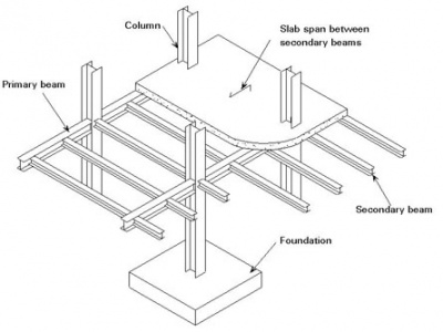
The principal structural elements of a typical multi-storey building comprise floors, beams and columns. A wide variety of alternative forms and arrangements can be used in multi-storey steel framed structures to deliver the benefits of:
- Economy
- Shallow floor construction
- Integration of services
- Flexible, column-free floor space
- Reduced foundations
- Rapid on-site construction.
[top]Factors affecting choice of structural system
Main articles: Long-span beams, Floor systems, Service integration, Braced frames, Continuous frames, Simple connections, Moment resisting connections, Steel construction products, Composite construction, Facades and interfaces
Floor grids define the spacing of the columns in orthogonal directions, which are influenced by:
- The planning grid (typically based on multiples of 0.6 m, 1.2 m or 1.5 m)
- The column spacing on the facade, to suit the external envelope (typically 5.4 m to 7.5 m)
- The intended use of the internal space
- The requirements for building services distribution.
The British Council for Offices (BCO) Guide to Specification[1] provides extensive guidance on the preparation of scheme designs.
For naturally ventilated offices, a building width of 12 m to 15 m is typically used, which can be achieved by two spans of 6 m to 7.5 m, with a column placed adjacent to a central corridor. Natural lighting also plays a role in choice of the width of floor plate. In larger buildings, a long-span solution provides a considerable enhancement in flexibility of layout. For air conditioned offices, a clear span of 15 m to 18 m is often used.
Floor-to-floor height will be an important consideration at the concept design stage. The table below gives typical floor to floor heights for buildings of different use.
| Prestige office | 4 - 4.2 m |
| Speculative office | 3.6 - 4.0 m |
| Renovation project | 3.5 - 3.9 m |
If planning restrictions limit overall building height, shallow floor solutions may be adopted, or solutions that involve integrating the services within the structural depth. Typical structural depths for different types of construction are given in the table below.
| Composite beam construction | 800 mm - 1200 mm |
| Cellular beams (with service integration) | 800 mm - 1100 mm |
| Precast concrete floors (7.5 m span) | 1200 mm - 1200 mm |
| Precast concrete floors (14 m span) | 1450 mm - 1450 mm |
| Shallow floor system or integrated beams | 600 mm - 800 mm |
[top]Stability systems

The structural system required for stability is primarily influenced by the building height. For buildings up to eight storeys height, the steel structure alone may be designed to provide stability, but for taller buildings, concrete or braced steel cores are more efficient structurally. The following structural systems may be considered for stability.
[top]Braced frames
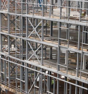
For buildings up to eight storeys high, braced steel frames are commonly used with bracing members generally located within a cavity in the facade, or around stairs or other serviced zones.
A steel braced frame has three key advantages:
- A braced solution is less expensive than a continuous frame
- Responsibility for temporary stability lies with one organisation
- As soon as the steel bracing is connected, the structure is stable.
[top]Continuous frames
For buildings up to four storeys high, continuous frames may be used in which the multiple beam to column connections provide bending resistance and stiffness to resist horizontal loads. This is generally only possible where the beams are relatively deep (400 mm to 500 mm) and where the column size is increased to resist the applied moments. The connections between members are likely to be more expensive than those in braced frames.
[top]Concrete or steel cores
Concrete cores are the most practical system for buildings of up to 40 storeys high, with the concrete core generally constructed in advance of the steel framework. In this form of construction, the beams often span directly between the columns on the perimeter of the building and the concrete core. Special structural design considerations are required for:
- The beam connections to the concrete core
- Fire safety and robustness of the long-span construction.
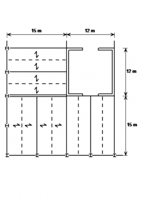
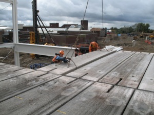
Typical beam layout around a concrete core
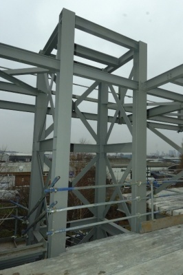
A braced steel core


Braced steel cores may be used as an economic alternative where speed of construction is critical. Such cores are installed with the rest of the steelwork package. An example of a braced steel core is shown in the figure above middle.
Guidance for the design of cast-in steel plates for connecting structural steel beams to concrete core walls is available in SCI-P416. This publication provides a model for the design of simple connections that transfer shear force due to permanent and variable loads and a non-coincident axial tie force resulting from an accidental load case. It points out additional issues which must be considered where coincident shear forces and axial forces are to be dealt with. A sample design of a simple connection for a 610 serial size UB is presented, and the design of punching shear reinforcement for the wall is included. The guide discusses the responsibilities of the building structural engineer and the steelwork contractor and suggests where the responsibilities are best divided. It also considers the impact of deviations between the theoretical positions of the parts of the connection and their as-erected positions.
[top]Columns
Columns in multi-storey steel frames are generally H sections , predominantly carrying axial load. When the stability of the structure is provided by cores, or discreet vertical bracing, the beams are generally designed as simply supported. The generally accepted design model is that nominally pinned connections produce nominal moments in the column, calculated by assuming that the beam reaction is 100 mm from the face of the column.
For ease of construction, columns are usually erected in two, or sometimes three storey sections, i.e. approximately 8 m to 12 m in length. Column sections are joined with splices , typically 300 mm to 600 mm above the floor level.
[top]Floor systems
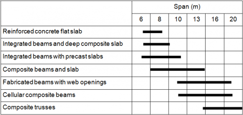
A wide range of floor solutions is available. Although steel solutions are appropriate for short spans (typically 6 m to 9 m), steel has an important advantage over other materials in that long-span solutions (between 12 m and 18 m) can be easily provided. This has the key advantage of column-free space, allowing future adaptability, and fewer foundations.
Floors spanning onto the steel beams will normally be either precast concrete units, or composite floors. The supporting beams may be below the floor, with the floor bearing on the top flange (often known as "downstand" beams), or the beams may share the same zone with the floor construction, to reduce the overall depth of the zone. The available construction zone is often the determining factor when choosing a floor solution.
| Form of construction | Typical solution |
|---|---|
| Low rise, modest spans, no restriction on construction depth | Downstand beams precast units or composite floors |
| Modest spans (less than 9 m), restricted construction depth | Integrated solutions – precast or composite floors |
| Low rise, long span (e.g. 15 m) | Downstand beams in the façade. Composite floors with secondary steel beams spanning 15 m |
| Medium and high rise, modest spans, no restriction on construction depth | Downstand beams, composite construction |
| Medium and high rise, long spans (to 18 m) restricted construction depth | Composite floors with cellular long span secondary steel beams |
The span range of various structural options in both steel and concrete are shown in the table. Long-span steel options generally provide for service integration for spans of over 12 m. Cellular beams and composite trusses are more efficient for long-span secondary beams, whereas fabricated beams are often used for long-span primary beams.

Long-span beams have gained in popularity in the commercial building sector because they offer the following benefits in design and construction:
- Internal columns are eliminated, leading to more flexible and efficient use of internal space
- Services can be integrated within the depth of the structure, and so the floor to floor depth is not increased
- Fewer components are required (typically 30% fewer beams) leading to reduced construction and installation time
- Fire protection costs can be reduced due to the massivity (weight : exposed profile) of the longer span members
- Steelwork costs are not increased significantly, despite the longer spans.
[top]Foundations
In inner city and on difficult or brownfield sites, the time and cost of constructing the foundations has a major effect on the viability of a project. Although the weight of the frame is relatively small compared with the floors and walls, a steel frame can be significantly lighter than a comparable reinforced concrete frame. Further reductions in weight can be achieved by using light floor construction such as composite metal deck floors and lightweight concrete.
Difficult ground conditions may dictate the column grid. Long spans may be required to bridge obstructions in the ground. More generally, widely spaced columns reduce the number of foundations, simplifying the substructure construction and reducing cost.
[top]Integration of building services
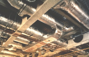

Service runs can be integrated within the depth of the structure or separated by fixing them at a lower level.
Separation of zones usually requires confining the ducts, pipes and cables to a horizontal plane below the structure, which will increase the overall floor construction. However, the services remain readily accessible for maintenance and future refitting.
Integration of services and structure reduces the construction depth but requires a perforated structure; installation and subsequent refitting of services may be more difficult.
[top]External envelope
Cladding systems that are used in multi-storey buildings depend on the building height and the degree of fenestration. Fully glazed facades are widely used, although provision for solar shading generally has to be made. Cladding systems include:
Brickwork
Ground supported up to 3 storeys. Supported by stainless steel angles attached to edge beams for taller buildings.
Glazing systems
Generally triple glazing or double layer facades supported on aluminium posts or glass fins.
Curtain walling
Aluminium or other lightweight facade that is attached to the perimeter steelwork.
Insulated render or tiles
Cladding system supported on light steel infill walls, mainly used in public sector buildings and residential buildings.
The external skin of a multi-storey building is usually supported off the structural frame. In most high quality commercial buildings, the cost of external cladding systems greatly exceeds the cost of the primary structure. This influences the design and construction of the structural system in the following ways:
- Reducing the floor zone may be cost-effective as it reduces the area of cladding.
- The perimeter structure must provide a satisfactory platform to support the cladding system and be sufficiently stiff to meet any deflection criteria.
[top]Structural principles
Main articles: Modelling and analysis, Design codes and standards, Portal frames, Allowing for the effects of deformed frame geometry
Once the structural concept has been fixed, the structural design may be completed. The structural design process involves the following steps:
- Calculating the permanent actions and determining the variable actions
- Identifying the load paths that carry the applied actions (vertical and horizontal) to the foundations
- Selecting preliminary sizes for members
- Analysis of the structure, if necessary, to determine design effects on individual members and deflections
- Analysis of the structure to assess sensitivity to second-order effects, allowing for these if necessary
- Verifying the members by ensuring the design resistance exceeds the design effects
- Verification of the members, and the frame, by ensuring the deflections do not exceed the limits given in the design Standard, or those specified by the Client.
[top]Variable actions
Characteristic variable actions include:
- Imposed floor loads
- Imposed loads on roofs
- Wind actions
- Snow loads
- Actions on structures exposed to fire
- Actions during execution of buildings (for example during concreting of composite slabs and beams)
- Accidental actions (used when considering the requirement to avoid disproportionate collapse)
Characteristic variable actions should be determined from the appropriate parts of BS EN 1991-1[2] and the relevant UK National Annexes[3].
[top]Analysis
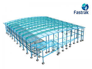

(Fastrak model courtesy of Trimble)
For 'simple construction', frame analysis will not be necessary at the Ultimate Limit State (ULS), as the members can be designed in isolation. It may be necessary (or convenient) to use analysis software to determine the lateral deflections at the Serviceability Limit State (SLS) and when assessing frame stability. Analysis will be required for continuous frames.
Generally, elastic analysis is used. Plastic analysis (and elastic-plastic analysis) is generally only used for the design of portal frames .
Although manual methods of analysis may be used, most designers find it convenient to use readily available software .
Most software contains libraries of all the standard steel sections, with the associated member properties used in the analysis. Non-standard members may be modelled with equivalent section properties. Tapered or haunched members may be modelled with a number of short elements, each with different section properties. Curved members may be modelled with a series of straight members.
Common UK practice is to assume joints are either nominally pinned (and modelled as perfectly pinned) or nominally rigid (and modelled as perfectly rigid). It is then important to ensure that the physical details correspond to the design assumptions.
[top]Sensitivity to second-order effects
All frames experience second-order effects, typically because under lateral loads (or simply due to frame imperfections), the vertical loads are no longer concentric with the bases. The effect of this displacement is not accounted for in a first-order analysis. Some frames are sufficiently stiff such that second-order effects are small enough to be ignored. When second-order effects must be accounted for, this can be achieved by using second-order analysis, or by a simple amplifier of the lateral loads.
All frames must be assessed for sensitivity to second-order effects, and these effects allowed for if necessary.
[top]Design Standards
Main articles: Design codes and standards
The over-arching requirement for design in the UK is to satisfy the Building Regulations. Practically, design of steel structures will generally be in accordance with BS 5950[4] or the Eurocodes .
[top]Building Regulations
Building Regulations require that a safe structure be constructed. Although a series of design Standards are cited in the Regulations, there is no absolute requirement that the listed Standards are used for design.
[top]BS 5950
Although BS 5950[4] was withdrawn in March 2010, it is likely to be used for steel building design for a number of years. The advantages of design to BS 5950 include:
- Familiarity with the Standard enjoyed by experienced designers
- The extensive use of look-up tables within the Standard
- The specific sections of the Standard devoted to particular building types, such as portal frames.
[top]Eurocodes
The Eurocodes are a set of unified structural design standards for use across Europe, developed by CEN (European Committee for Standardisation), to cover the design of all types of structures in steel, concrete, timber, masonry and aluminium.
In the UK, the Eurocodes are published by BSI under the designations BS EN 1990 to BS EN 1999; each of these ten Eurocodes is published in several Parts and each Part is accompanied by a UK National Annex (which must be used for construction in the UK) that adds certain UK-specific provisions.
In addition to the Eurocodes and the National Annex, non-contradictory complementary information (NCCI) is provided, to provide further guidance on the application of the Eurocodes.
[top]National Annexes
The National Annex (NA) is an essential document when using any Eurocode Part; the relevant NA covers the country where the construction will take place. Where the opportunity is given in the text of the Eurocode, the National Annex will:
- Specify the value of factors, modify limiting values or formulae
- Specify which design method may be used
- Specify which options may be used, if they are given in the Eurocode
- State whether an informative annex may be used - such annexes are explicitly identified as being open to National acceptance.
- Identify NCCI.
[top]NCCI
The National Annex may give references to publications and other guidance containing non contradictory complementary information (NCCI) that will assist the designer when designing a structure to the Eurocodes.
The Eurocodes omit some design guidance where it is considered to be readily available in text books or other established sources. Publications that contain such design guidance may be referenced in the National Annex as NCCI.
Several 'Published Documents' (PDs) are available, published by BSI . These NCCI documents are informative, without the status of a Standard, but are generally helpful reference documents for designers.
[top]Basis of structural design
BS EN 1990[5] can be considered as the 'core' document of the structural Eurocode system as it establishes the principles and requirements for the reliability, serviceability and durability of structures. It also describes the basis for structural design and verification. The main sections of BS EN 1990[5] include:
- Requirements
- Principles of limit state design
- Basic variables
- Structural analysis and design assisted by testing
- Verification by the partial safety factor method.
Designers will refer to BS EN 1990[5] (and its National Annex[6]) for load factors and combination factors, used when determining design combinations of actions (ULS loads).
[top]BS EN 1993-1 (Eurocode 3)
BS EN 1993-1 Eurocode 3: Design of steel structures comprises a set of general rules in twelve parts (BS EN 1993-1-1[7] to BS EN 1993-1-12[8]) for all types of steel buildings. The commonly used Parts include:
- BS EN 1993-1-1[7]. This Part provides most of the general rules used in the design of steel buildings, including material properties, guidance on analysis, the assessment of second-order effects and the calculation of member resistances.
- BS EN 1993-1-5[9]. This Part provides rules for members fabricated from plate, but also provides the rules for calculating the resistance of webs - typically verified under concentrated loads.
- BS EN 1993-1-8[10]. This Part provides the design rules for joints. It includes rules for the resistance of joint components, such as bolts and welds.
Additional rules are provided in separate Parts for other structures, e.g. BS EN 1993-2[11] provides design rules for bridges.
A comprehensive range of design guidance is available for use in the UK, all incorporating the influence of the UK National Annexes.
[top]BS EN 1994 (Eurocode 4)
BS EN 1994[12] covers the design of composite structures and elements .
Guidance is available covering the design of composite floors in accordance with Eurocode 4 in SCI publication Composite design of steel framed buildings (P359).
[top]Common structural systems
Main articles: Braced frames, Continuous frames, Composite construction, Floor systems, Steel construction products, Long-span beams
Building frames may be broadly classified by their stability system, as braced or continuous frames . A portal frame is a particular type of a continuous frame. For multi-storey frames, a braced frame is likely to be most economical, because the fabrication effort for the joints in braced frames is generally much less than for joints in continuous frames. Continuous frames must be used when bracing cannot be provided within the structure.
Within both types of frame, a wide range of floor systems is available. Several floor systems utilise the benefits of composite construction , which will be the de facto solution for many structures. The floor systems in common use are briefly described in the following sections
[top]Composite construction

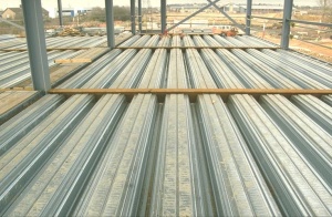
Composite construction is the dominant form of construction for the multi-storey building sector. Its success is due to the strength and stiffness that can be achieved, with minimum use of materials, utilising the compressive strength of concrete and the tensile strength of steel. Composite floors offer significant advantages related to speed of construction and reduced overall construction depth.
Composite floor slabs generally use either relatively shallow profiled steel decking , typically spanning up to 3.75 m, or deep deck systems, spanning up to 9 m (if propped during construction). Composite floor slabs may also be constructed using pre-cast planks as the permanent formwork.
Floor slabs may be formed from pre-cast planks, but still allow the supporting beam to be designed as a composite member.
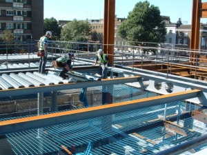
Composite beams involve the transfer of force between the steel section and the concrete which it supports, preventing slip and thus ensuring the two elements perform as a composite whole. For beams located wholly under the slab (known as "downstand" beams) the transfer of force is commonly achieved using headed shear studs, which are attached to the upper flange of the steel beam. Studs are usually welded on site, through the decking, to the (unpainted) top flange of the beam. Alternatively, smaller shear connectors may be shot-fired to the steel beam. In some forms of construction, the shear bond between the steel member and the encasing concrete is sufficient to provide composite action without additional shear connectors.
Different types of composite beam are available:
- Downstand beams - the steel beam is wholly below the concrete slab
- Shallow floor solutions - the steel beam is at least partially integrated within the depth of the floor slab.
- Types of composite beams
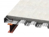
Conventional "downstand" beam
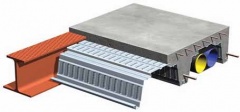
Integrated beam with deep decking


[top]Precast concrete units
Precast concrete units may be used in conjunction with steel beams. The units may be solid or hollow-core, and with tapered or bluff ends. They are normally prestressed. The steel beams and precast units may be designed as a composite member, provided specific detailing rules are satisfied to ensure the necessary composite behaviour.

(Image courtesy of Severfield (Design & Build) Ltd.)
[top]Integrated floor solutions

Integrated (or 'shallow') floors offer a range of benefits, including a reduced construction depth (compared to an orthodox "downstand" solution) and, in some solutions, a virtually flat soffit, allowing easy location of services.
A number of integrated floor solutions are available, including a range of rolled and fabricated options providing shallow depth members with wide bottom flanges, so that precast planks or steel decking can be placed on the bottom flange.
[top]Long-span beams
Long spans result in flexible, column-free internal spaces, reduced substructure costs, and reduced erection times. This broad range of benefits means that they are commonly used in a wide range of building types.
Long-span beam options include:
- Composite beams with web openings
- Cellular composite beams
- Tapered girders.
The design of long-span steel and (steel-concrete) composite beams is generally carried out in accordance with BS 5950[4], BS EN 1993[13] or BS EN 1994[12]. For some types of beam this codified guidance is complemented by specific design guidance, such as that on the design of beams with large web openings, or manufacturers' software.
[top]Trusses

(Image courtesy of Severfield (UK) Ltd.)
Main article: Trusses
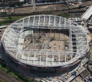
A truss is essentially a triangulated system of straight interconnected structural elements. The most common use of trusses is in buildings, where support to roofs, the floors and internal loading such as services and suspended ceilings, is readily provided. Trusses are commonly used in a range of buildings including airport terminals, aircraft hangers, sports stadia roofs, auditoriums and other leisure buildings . Trusses are also used to provide large column-free spaces in commercial buildings. The main reasons for using trusses are:
- To span large distances
- To provide a lightweight solution
- To control deflection
- To support heavy loads.
Trusses may be exposed within the structure and be fabricated from hollow sections for aesthetic appeal. Large loads may require the use of open sections (UKC, typically) or sections built up from plate. In all cases, the additional fabrication costs make trusses more expensive than conventional beam and column structures.
[top]Portal frames
Main articles: Portal frames, Moment resisting connections, Single storey industrial buildings
Portal frames are low-rise structures, comprising columns and rafters, connected by moment-resisting connections. The resistance to lateral and vertical actions is provided by the rigidity of the connections and the bending stiffness of the members, which is increased by a substantial haunch to reinforce the rafter sections. This form of continuous frame is stable in its plane and provides a clear span that is unobstructed by bracing. Bracing is provided in the longitudinal direction, between frames.
Portal frames are structurally efficient and lightweight, accounting for over 90% of the single-storey market in the UK. Portal frames are used for industrial, storage , retail and commercial applications.
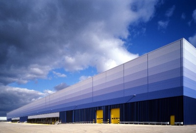
Steel framed, steel clad single storey distribution warehouse building
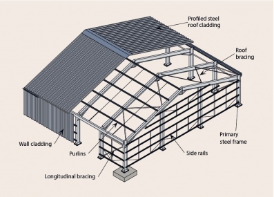
Principal components of a portal framed building


In addition to a primary steel structure, portal framed buildings also commonly include:
- Secondary, thin gauge cold-rolled steel members (purlins and side rails) which restrain the primary steel members and support the cladding
- Profiled steel wall and roof cladding.
[top]Member design to BS EN 1993
Main article: Member design
Steel member design is based on the requirements given in BS EN 1993-1-1[7] . The overall process in member design involves:
- Classification of the cross section
- Cross-sectional resistance
- Member buckling resistance
- Resistance to combined axial loading and bending, where applicable.
Member design is often completed using software, of by reference to the resistance tables in the 'Blue Book'.
[top]Connections
Main articles: Cost planning through design stages, Braced frames, Continuous frames, Simple connections, Moment-resisting connections
The cost of connections is a significant proportion of the overall cost of the structure and the use of standardised, simple details is recommended wherever possible. Moment resisting connections will undoubtedly be more expensive than the nominally pinned connections used in braced construction .
Design of joints in steel structures in the UK is covered by BS EN 1993-1-8[10] and its UK National Annex[14]
BS EN 1993-1-1[7] requires that connection behaviour be accounted for in frame analysis, if it is significant. Nominally pinned connections and continuous connections may be modelled as pinned and rigid (respectively) in the analysis, but semi-continuous joint behaviour should be taken into account.
BS EN 1993-1-8[10] provides numerical methods to classify a joint, but offers the option that joints may be classified on the basis of previous satisfactory performance. The UK National Annex[14] specifies that joints designed in accordance with the industry standard guides (on nominally pinned and moment-resisting connections) are nominally pinned and rigid respectively. Classification in accordance the guidance in the UK NA is recommended.
[top]Simple connections
Simple connections are nominally pinned connections that transmit end shear only and do not transfer significant moments. This assumption underpins the design of multi-storey braced frames in the UK, in which the beams are designed as simply-supported and the columns are designed for axial load and the small nominal bending moments induced by the end reactions from the beams.
- Nominally pinned connections

End plate connections

Fin plate connection


Simple connections include:
- Beam-to-beam and beam-to-column connections using:
- Partial depth end plates
- Full depth end plates
- Fin plates
- Column splices (bolted cover plates and end plates)
- Column bases
[top]Moment-resisting connections
Moment resisting connections are used in continuous frames . Connections in multi-storey frames are most likely to be full depth end plate connections and extended end plate connections.
Connections in portal frames will be haunched at the eaves, often with stiffeners in the column member. The apex connection may have a small haunch or a simple extended end plate.
Moment-resisting connections may also be provided by providing a welded connection between members.
- Typical portal frame connections
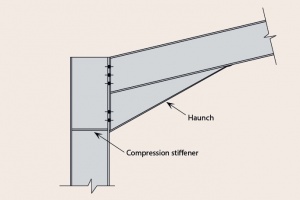
Eaves connection
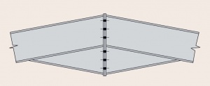
Apex connection


[top]Structural robustness
Main articles: Structural robustness
Building Regulations require that all buildings should be designed to avoid disproportionate collapse . Commonly, this is achieved by designing the joints in a steel frame (the beam-to-column connections and the column splices) for tying forces. Guidance on the design values of tying forces is given in BS EN 1991-1-7[15] Annex A, and its UK National Annex[16] .
Two generic types of strategy for designing robust structures for accidental actions are provided in BS EN 1991-1-7[15] :
- Strategies based on identified accidental actions.
- Strategies based on unidentified accidental actions.
The robustness requirements relate to the building Class (the type, size and use of a building) and establish required levels of robustness for different building Classes.
Detailed guidance on robustness strategies for steel framed buildings designed in accordance with the Eurocode is available.
[top]Specification of structural steelwork
Main articles: Steelwork specification, Fabrication, Construction
The purpose of a structural steelwork specification is to state what materials and products should be used and how work (fabrication and erection ) should be carried out, in order to ensure that the completed structure meets the designer's assumptions and the client's needs.
Under the Eurocode system, fabrication and erection should comply with the execution standard BS EN 1090[17] which covers material specification, component specification, workmanship and tolerances.
In the UK, the National Structural Steelwork Specification (NSSS) is recommended for use with steel building structures which are identified by the designer as Execution Class 2 (EXC2). The NSSS complements BS EN 1090[17], by providing additional requirements on transfer of information, weld inspection etc, and other requirement which are not addressed in BS EN 1090[17].
[top]BS EN 1090 Execution of steel structures
BS EN 1090 Execution of steel structures and aluminium structures consists of three parts:
- Part 1[18]: Requirements for conformity assessment of structural components
- Part 2[19]: Technical requirements for steel structures
- Part 3[20]: Technical requirements for aluminium structures.
BS EN 1090-2[19] specifies general requirements for the execution of structural steelwork as structures or as manufactured components, depending on the Execution Class of the structure. Four Execution Classes are identified and more onerous fabrication and erection requirements are demanded for the higher numbered Execution Classes.
BS EN 1090-2[19] also gives guidance for the steelwork of steel and concrete composite structures designed in accordance with BS EN 1994[12].
[top]The National Structural Steelwork Specification for Building Construction (NSSS)
The 7th Edition of the NSSS covers structures designed in accordance with either BS 5950 or Eurocode 3 and is for Class 2 structures to be executed in accordance with BS EN 1090[17].
The principal topics covered in the NSSS are as follows:
- Information required by the Steelwork Contractor
- Materials
- Information provided by the Steelwork Contractor
- Workmanship
- Welding
- Bolting
- Fabrication accuracy
- Erection
- Erection accuracy
- Protective treatment (corrosion and fire)
- Quality management
These topics present, in a concise manner, the requirements in BS EN 1090[17] for orthodox building (Execution Class 2) structures.
Provision is included for modifications to suit any unorthodox construction.
The 7th Edition of the NSSS also contains an Annex of the requirements for Execution Class 3 for static structures and an Annex giving general guidance on Execution Class 3 for buildings subject to fatigue, such as crane supporting structures.
[top]NSSS Annex J - Sustainability Specification

The 1st edition of the Sustainability Specification for structural steelwork for building construction was published by BCSA in January 2022, and is freely available here. Due to come into force on 1st June 2022, this document will constitute a new Annex J to the National Structural Steelwork Specification for Building Construction (NSSS) when revised in its 8th edition.
Given demands to promote more sustainable construction, and particularly in the context of the climate emergency, this document specifies general requirements and practices for achieving environmentally sustainable steel building construction. Prepared under the guidance of a steering committee comprised of structural steel suppliers, steelwork contractors, designers, and individual sustainability experts from BCSA, SCI, and IStructE, it supplements the requirements of Clauses 1 to 11 of the NSSS and includes guidance on both the sustainable design of structural steelwork and the specification for sustainable fabrication of structural steelwork.
[top]References
- ↑ Guide to Specification, British Council for Offices, 2019
- ↑ BS EN 1991-1 Eurocode 1. Actions on structures. General actions. (Various Parts). BSI
- ↑ NA to BS EN 1991-1 UK National Annex to Eurocode 1. Actions on structures. General actions. (Various Parts). BSI
- ↑ 4.0 4.1 4.2 BS 5950 Structural use of steelwork in building (Various Parts). BSI
- ↑ 5.0 5.1 5.2 BS EN 1990:2002+A1:2005. Eurocode: Basis of structural design. BSI
- ↑ NA to BS EN 1990:2002+A1:2005. UK National Annex for Eurocode: Basis of structural design. BSI
- ↑ 7.0 7.1 7.2 7.3 BS EN 1993-1-1:2005+A1:2014, Eurocode 3: Design of steel structures. General rules and rules for buildings, BSI
- ↑ BS EN 1993-1-12:2007 Eurocode 3. Design of steel structures. Additional rules for the extension of EN 1993 up to steel grades S 700, BSI.
- ↑ BS EN 1993-1-5:2006+A2:2019. Eurocode 3: Design of steel structures Plated structural elements. BSI
- ↑ 10.0 10.1 10.2 BS EN 1993-1-8:2005. Eurocode 3: Design of steel structures. Design of joints, BSI
- ↑ BS EN 1993-2:2006 Eurocode 3. Design of steel structures. Steel bridges. BSI
- ↑ 12.0 12.1 12.2 BS EN 1994 Eurocode 4: Design of composite steel and concrete structures. (Various Parts). BSI
- ↑ BS EN 1993 Eurocode 3: Design of steel structures. (Various Parts) BSI
- ↑ 14.0 14.1 NA to BS EN 1993-1-8:2005 UK National Annex to Eurocode 3: Design of steel structures. Design of joints, BSI
- ↑ 15.0 15.1 BS EN 1991-1-7:2006+A1:2014. Eurocode 1: Actions on structures. General actions. Accidental actions. BSI
- ↑ NA+A1:2014 to BS EN 1991-1-7:2006+A1:2014. UK National Annex to Eurocode 1: Actions on structures. Accidental actions, BSI
- ↑ 17.0 17.1 17.2 17.3 17.4 BS EN 1090 Execution of steel structures and aluminium structures (Various Parts), BSI.
- ↑ BS EN 1090-1:2009+A1:2011 Execution of steel structures and aluminium structures. Requirements for conformity assessment of structural components BSI.
- ↑ 19.0 19.1 19.2 BS EN 1090-2:2018 Execution of steel structures and aluminium structures. Technical requirements for steel structures. BSI.
- ↑ BS EN 1090-3:2008 Execution of steel structures and aluminium structures. Technical requirements for aluminium structures. BSI.
[top]Further reading
- Steel Designers' Manual 7th Edition. Editors B Davison & G W Owens. The Steel Construction Institute 2012
[top]Resources
- SCI P355 Design of Composite Beams with Large Web Openings, 2011
- SCI P358 Joints in Steel Construction: Simple Joints to Eurocode 3, 2014
- SCI P359 Composite Design of Steel Framed Buildings, 2011
- SCI P360 Stability of Steel Beams and Columns, 2011
- SCI P361 Steel Building Design: Introduction to the Eurocodes, 2009
- SCI P362 Steel Building Design: Concise Eurocodes, 2009
- SCI P363 Steel Building Design: Design Data, 2013
A web-based interactive version of the 'Blue Book', is also available. - SCI P364 Steel Building Design: Worked Examples - Open Sections, 2009
- SCI P365 Steel Building Design: Medium Rise Braced Frames, 2009
- SCI P374 Steel Building Design: Worked Examples - Hollow Sections, 2008
- SCI P375 Fire Resistance Design of Steel Framed Buildings, 2012
- SCI P385 Design of Steel Beams in Torsion, 2011
- SCI P391 Structural Robustness of Steel Framed Buildings, 2011
- SCI P394 Wind Actions to BS EN 1991-1-4, SCI, 2013
- SCI P397 Elastic Design of Single-span Steel Portal Frame Buildings to Eurocode 3, 2013
- SCI P398 Joints in Steel Construction: Moment-resisting Joints to Eurocode 3, 2013
- SCI P399 Design of steel portal frame buildings to Eurocode 3, 2015
- SCI P405 Minimum degree of shear connection rules for UK construction to Eurocode 4, 2015
- SCI P416 The design of cast-in plates, 2017
- SCI P419 Brittle fracture: Selection of steel sub-grade to BS EN 1993-1-10, 2017
- National Structural Steelwork Specification (7th Edition), 2020, (Publication No. 62/20), BCSA
- National Steelwork Specification for Building Construction, Annex J - Sustainability Specification, Publication No. 65/2022, BCSA, 2022
- Handbook of Structural Steelwork (Eurocode Edition), Publication No. 55/13, BCSA 2013
- Historical Structural Steelwork Handbook, Publication No. 11/84, BCSA 1984
- Historical Structural Iron and Steel Sections, Properties of historical cast iron, wrought iron and steel sections, Publication No. 61/19, BCSA 2019
- Advisory Desk Notes
Member design tools:
- Compression resistance design tool
- Bending resistance design tool
- Combined axial compression and bending resistance design tool
- Columns in simple construction design tool
- Resistance of beams at elevated temperature
- Resistance of columns at elevated temperature
- Composite beam checking tool
- Elastic critical moment for lateral torsional buckling calculation tool
- Frame stability tool
- Concrete filled structural hollow section design tool
Connection design tools:
Other design tools:
[top]See also
- Steel manufacture
- Steel construction products
- Steel material properties
- Concept design
- Service integration
- Braced frames
- Continuous frames
- Composite construction
- Floor systems
- Long-span beams
- Trusses
- Portal frames
- Design codes and standards
- Modelling & analysis
- Allowing for the effects of deformed frame geometry
- Member design
- Simple connections
- Moment resisting connections
- Structural robustness
- Steelwork specification
- UKCA marking
- Design software and tools