


Difference between revisions of "Continuous frames"
| Line 98: | Line 98: | ||
Allowance may be by a [[Modelling and analysis#Second-order analysis|second-order analysis]], or by modifying (amplifying) the results of a [[Modelling and analysis#First-order analysis|first-order analysis]]. | Allowance may be by a [[Modelling and analysis#Second-order analysis|second-order analysis]], or by modifying (amplifying) the results of a [[Modelling and analysis#First-order analysis|first-order analysis]]. | ||
| − | [[Modelling and analysis#First-order analysis|First-order analysis]] may be used for the structure, if the increase of the relevant internal forces or moments or any change of structural behaviour caused by deformations can be neglected. Clause NA.2.9 of the UK National Annex to BS EN 1993-1-1<ref name="UKNAtoBSEN1993-1-1">NA to BS EN 1993-1-1:2005+A1: | + | [[Modelling and analysis#First-order analysis|First-order analysis]] may be used for the structure, if the increase of the relevant internal forces or moments or any change of structural behaviour caused by deformations can be neglected. Clause NA.2.9 of the UK National Annex to BS EN 1993-1-1<ref name="UKNAtoBSEN1993-1-1">NA+A1:2014 to BS EN 1993-1-1:2005+A1:14, UK National Annex to Eurocode 3: Design of steel structures General rules and rules for buildings, BSI</ref> clause 5.2.1 (3) states that this condition may be assumed to be fulfilled if the following criterion is satisfied: |
[[File:C7fig6.JPG|100px]] for [[Modelling_and_analysis#Elastic analysis|elastic analysis]] | [[File:C7fig6.JPG|100px]] for [[Modelling_and_analysis#Elastic analysis|elastic analysis]] | ||
Revision as of 10:13, 21 May 2020
This article considers continuous frames in multi-storey buildings. Continuous frames are moment resisting where the beam to column connections are classified as rigid and are designed to transmit the beam end moments and shear forces into the column. No bracing system is required to resist lateral loads and frame stability is provided by the rigidity of the connections and the stiffness of the members only.
Frames can also be designed as 'semi-continuous', however, this type of frame is not considered here. Further information on 'semi-continuous' frames is provided in SCI P183 and SCI P263.
Continuous frames for buildings are used where vertical bracing is not acceptable, i.e. for aesthetics or access reasons. A key advantage of continuous frames is the opportunity to minimize the depths of the beams.
This article considers how continuous frames are analysed and designed and the types of connections that are used.

[top]Introduction
Continuous frames are moment resisting with rigid connections between beams and columns. No account is taken of local beam-column connection rotations in global frame analysis and the connections are designed to transmit the resulting beam end moments and shear forces into the column.
A continuous frame is capable of resisting lateral loads without relying on an additional bracing system for stability. The frame itself resists design forces due to vertical loading and lateral forces, i.e. wind loading, and has adequate lateral stiffness against sway when subjected to these horizontal loads.
For the frame to be continuous the connections must also be 'rigid'. Reference therefore should be made to BS EN 1993-1-8[1], the corresponding UK National Annex[2] and SCI P398 ('Green Book) to assess joint classification and connection details.
The advantages of continuous frames are:
- For architectural and functional reasons (aesthetics, obstructions and accessibility), it can be advantageous in omitting triangulated bracing systems or solid wall systems in buildings
- The deflections of continuous beams are lower than those of simply supported beams
- Beams can be less deep than simply supported beams
- The floors are less sensitive to vibrations
- Connections perform better in load reversal situations or in earthquakes
- Adding redundancy to the structure increases robustness.
The disadvantages are:
- The connections are more complex and the erection process is more complicated
- The internal forces in the columns are increased
- The overall cost of the structure is greater, mainly due to the additional cost of rigid connections.
Since ensuring stability by frame action is less economical than by bracing, a combination of the two systems can provide an efficient and balanced solution. It is possible to have continuous frames in one direction and to use bracing for stability in the perpendicular direction.
Structures made of continuous frames in both directions are exceptional. They can be recommended for buildings with special requirements, e.g. medical, research, white rooms, and buildings housing equipment sensitive to deflections and vibrations, etc.
[top]Design
The effective design of a continuous frame for a multi-storey building requires an appreciation of the behaviour of the frame under loading. Various types of continuous frames can be used and two common types are shown in the figure below.

|

|
|
| Entire frame continuous | Discrete continuous frame |
A continuous frame can be continuous throughout its entire frame where all the joints are 'rigid' (left hand figure), or where only a discrete part of the frame is continuous (right hand figure). Both types of continuous frames provide appropriate lateral resistance due to lateral loading.
Before a detailed analysis and design of the frame is performed it is important that realistic preliminary beam section sizes and column section sizes are determined. The figure shows the bending moments acting on the beams and columns for vertical loading (floor/roof loads) only, and for horizontal loading (wind) only.
Realistic members sizes are required before an accurate assessment of frame stability can be completed and before the serviceability limit state (SLS) deflections can be calculated.
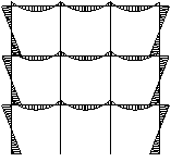
Bending moment diagram under vertical loading
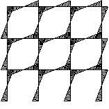
Bending moment diagram under horizontal loading


For multi-storey buildings where unbraced continuous frames are used, the critical case for design is usually the provision of adequate resistance to lateral loading at the Serviceability Limit State (SLS). Typically this requires that the relative horizontal deflection between floors is controlled and limited to a magnitude of storey height/300. As realistic member sections (beams and columns) have already been determined, satisfactory behaviour of the frame at SLS can be ascertained.
Analysis of the frame under vertical pattern loading will also need to be considered in order to include single and double curvature bending in the columns.
An important aspect in the design of a continuous frame is an appreciation of the lateral displacement between the base level and the first floor. This is particular important for 'pinned' column bases where a significant amount of lateral displacement can occur between the ground and the first floor of the frame. Consideration should therefore be given to moment resisting column bases, but noting the corresponding implications regarding loading transferred to the foundations and the corresponding increase in costs.
Assessment of the stability of the frame requires the frame to be assessed for its sensitivity to global and local imperfections and sway. Where the frame is sensitive to these effects, it will be necessary to re-analyse the frame to determine the additional forces and bending moments in the members, caused by these second-order effects.
Once accurate forces and bending moments are known, the beam and column sections can be verified. Finally, based on these forces and moments acting on the frame, the connections can be designed.
[top]Vertical loading on continuous frames
In order to ensure that the worst vertical load effects due to loading on the floors and the roof on the frame are obtained, it is necessary to consider realistic combinations of pattern loading. The imposed floor loading should be arranged in the most unfavourable but realistic pattern. Suggested combinations are shown in the figure below. The designer should however, apply engineering judgement to each situation. The imposed roof loading should generally not be patterned for the gravity load case.

|

|

|

|
| a) For maximum beam span moments | b) For mininmum beam span moments | c) For maximum single curvature bending in columns | d) For maximum double curvature bending in columns |
[top]Global analysis of continuous frames
Continuous frames, by their nature are more difficult to analyse than simple (nominally pinned) frames. Although elastic analysis or plastic analysis may be used to analyse continuous frames, plastic analysis is rarely used for multi-storey frames and hence will not be considered further here.
Multi-storey frames are statically indeterminate. The internal forces and moments may be determined by global analysis using either:
- First-order analysis, using the initial geometry of the structure or
- Second-order analysis, taking into account the influence of the deformation of the structure.
Allowing for second-order effects is only necessary if the effects of the deformed geometry increases the loading effects significantly or modifies significantly the structural behaviour.
Allowance may be by a second-order analysis, or by modifying (amplifying) the results of a first-order analysis.
First-order analysis may be used for the structure, if the increase of the relevant internal forces or moments or any change of structural behaviour caused by deformations can be neglected. Clause NA.2.9 of the UK National Annex to BS EN 1993-1-1[3] clause 5.2.1 (3) states that this condition may be assumed to be fulfilled if the following criterion is satisfied:
![]() for elastic analysis
where
for elastic analysis
where
αcr is the factor by which the design loading would have to be increased to cause elastic instability in the global mode
FEd is the design loading on the structure
Fcr is the elastic critical buckling load for global instability mode, based on initial elastic stiffnesses
For each storey of the building, αcr may be calculated using the approximate formula given by equation 5.2 in clause 5.2.1. Alternatively αcr can be determined using proprietary software packages.
If the influence of the deformation of the structure has to be taken into account, the amplifying factor in BS EN 1993-1-1[4] clause 5.2.2(5) may be used or a second-order analysis completed.
[top]Imperfections
Appropriate allowances need to be incorporated in the structural analysis to cover for the effects of imperfections, including residual stresses and geometrical imperfections such as lack of verticality, lack of straightness, lack of fit and any minor eccentricities present in the connections of the unloaded structure.
For continuous frames, imperfections to be considered include:
- Global imperfections for the frames
- Local imperfections for individual members
The assumed shape of the global imperfections may be derived from the elastic buckling mode of a structure in the plane of buckling considered. For frames sensitive to buckling in a sway mode the effect of imperfections are allowed for in frame analysis by means of an equivalent imperfection in the form of an initial sway. Clause 5.3.2 presents how these imperfections are determined. The use of Equivalent Horizontal Forces (EHF) is recommended.
Local imperfections for individual members are accounted for in member resistance calculations.
Elastic analysis of rigid frames is usually carried out using one of the many commercial software packages now available. In a first-order analysis, the software will calculate the moments and forces based on its un-deflected shape, ignoring any second-order effects due to sway.
[top]Moment resisting connections
Moment resisting connections are used in multi-storey continuous framed buildings. Typically, connections are full depth end-plate connections and extended end-plate connections. The most commonly used moment resisting connections are bolted end-plate beam-to-column connections; these are shown in the figures below.
- Commonly used moment resisting connections
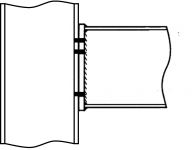
Full depth end plate
Extended end plate


Choice of connection type is almost always based on economic considerations where the connections are based on simplicity, duplication and ease of fabrication.
Instead of bolted beam-to-column connections, welded connections can also be used. These connections can provide full moment continuity but are expensive to produce. Where welded beam-to-column connections are specified they should be fabricated in the workshop. Welded connections are also used for the construction of buildings in seismic areas.
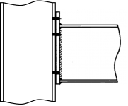
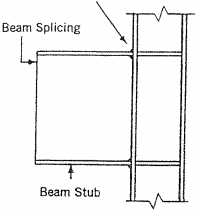
To minimise labour cost and to speed up site erection, site bolting instead of site welding should be used. If necessary, beam stubs can be shop welded to the column and connected to the beams by site bolting.
Design of connections in steel structures in the UK is covered by BS EN 1993-1-8[1] and its National Annex[2]. BS EN 1993-1-8[1] requires that joints are classified by stiffness (as rigid, semi-rigid or nominally pinned) or by strength (as full strength, partial strength or nominally pinned). The UK National Annex states that connections may be classified as rigid in accordance with the principles given in SCI P398.
For multi-storey un-braced frames, rotational stiffness is fundamental to the determination of frame stability. The designer must either evaluate connection stiffness (in accordance with BS EN 1993-1-8[1]) and account for this in the frame design and assessment of frame stability or, if rigid joints have been assumed in the frame analysis, ensure that the connection design matches this assumption.
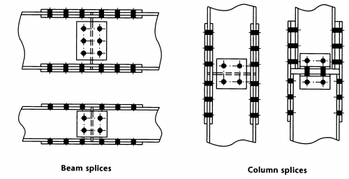
Other types of moment resisting connections used in continuous frames include:
- Splices in columns and beams
- Column bases
Typical bolted cover plate splices are shown in the figure below.

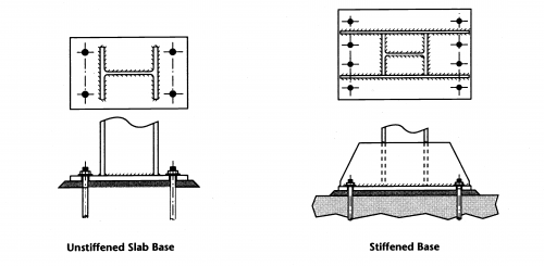
An example of a column base which is able to transmit moment and axial force between steel members and concrete substructures at the base of columns is shown in the figure below. The example shows a column base with an unstiffened base plate and one with additional stiffening.

Further information regarding moment resisting connection design can be obtained from the 'Green Book', SCI P398 which is based on BS EN 1993-1-8[1].
[top]References
- ↑ 1.0 1.1 1.2 1.3 1.4 BS EN 1993-1-8:2005. Eurocode 3: Design of steel structures. Design of joints, BSI
- ↑ 2.0 2.1 NA to BS EN 1993-1-8:2005. UK National Annex to Eurocode 3: Design of steel structures. Design of joints, BSI
- ↑ NA+A1:2014 to BS EN 1993-1-1:2005+A1:14, UK National Annex to Eurocode 3: Design of steel structures General rules and rules for buildings, BSI
- ↑ BS EN 1993-1-1:2005+A1:2014, Eurocode 3: Design of steel structures. General rules and rules for buildings, BSI
[top]Further reading
- Steel Designers' Manual 7th Edition. Editors B Davison & G W Owens. The Steel Construction Institute, 2012
[top]Resources
- SCI P398 Joints in Steel Construction: Moment-resisting Joints to Eurocode 3, 2013
- SCI P183 Design of Semi-Continuous Braced Frames, 1997
- SCI P263 Wind-moment Design of Low Rise Frames, 1999