


Concept design
This article presents information necessary to assist in the choice and use of steel structures at the concept design stage for modern multi-storey buildings and single storey buildings . The information is presented in terms of the design strategy, anatomy of building design and structural systems.
For multi-storey buildings the primary sector of interest is commercial buildings, but the same information may also be used in other sectors.
For single storey buildings the primary sector of interest is industrial buildings, but the same information can also be used in other sectors, such as commercial, retail and leisure.
Minimising embodied carbon and operational energy are important factors in any design, assessed alongside such things as selection of materials, grid arrangements, structural solutions, fire resistance and deconstruction. The ‘value’ of the activity undertaken within any structure is generally many multiples of the capital cost, so meeting the client’s needs (both immediate and allowing for future changes) is paramount.

Typical columns layout in an office building with an atrium
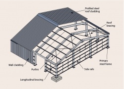
Arrangement of a single-storey building


[top]Multi-storey buildings

In multi-storey buildings , the design of the primary structure is strongly influenced by many issues, as defined below:
- The need to provide clear floor spans for more usable space
- The choice of cladding system
- Planning requirements, which may limit the building height and the maximum floor-to-floor zone
- The services strategy and effective integration of building services
- Site conditions, which dictate the foundation system and location of foundations
- Craneage limitations and storage space for materials and components
- Speed of construction, which may influence the number of components that are used and the installation process
- Reduction in embodied carbon.
Studies show that the cost of the building structure is generally only 10% of the total building cost - and the influence of the choice of structure on the foundations, services and cladding are often more significant. In reality, building design is a synthesis of architectural, structural, services, logistics and buildability issues. Steel frames are ideally suited for modern multi-storey commercial buildings.
[top]Hierarchy of design decisions
The development of any proposal for a construction project requires a complex series of design decisions that are inter-related. The process should begin with a clear understanding of the client requirements and of local conditions or regulations. Despite the complexity, it is possible to identify a hierarchy of design decisions. Firstly, planning requirements are likely to define the overall building form, which will also include aspects such as natural lighting, ventilation and services. The principal design choices that need to be made in close consultation with the client are:
- The depth of the floor zone and the overall structure/service interaction strategy
- The need for special structural arrangements in public spaces or circulation areas
- The provision of some tolerance between structure and services, to permit future adaptability
- The benefit of using longer spans, at negligible extra cost, in order to enhance flexibility of layout.
Based on the design brief, a concept design can then be prepared which is reviewed by the design team and client. It is at this early interactive stage where the important decisions are made that influence the cost and value of the final project. Close involvement with the client is essential.
[top]Anatomy of building design
The building design is dependent on various parameters; these include:
- Floor grid
- Building height
- Circulation and access space
- Services requirements and service integration.
[top]Floor grids
Floor grids define the spacing of the columns in orthogonal directions, which are influenced by:
- The planning grid (normally based on units of 300 mm but more typically multiples of 0.6, 1.2 or 1.5 m)
- The column spacing along the façades, depending on the façade material (typically 5.4 to 7.5 m)
- The use of the internal space, i.e. for offices or open plan space
- The requirements for building service distribution (from the building core).
Along the façade line, column spacings are normally defined by the need to provide support to the cladding system. For example, a maximum column spacing of 6 m is normally required for brickwork. This influences the column spacing internally, unless additional columns are used along the façade line. The span of the beams across the building normally conforms to one of the following column grid arrangement:
- Single internal line of columns, placed offset to the line of a central corridor. This is shown in the figure below
- Pairs of column lines on either side of a corridor
- Column-free internal spans with columns located along the façade line.


For naturally ventilated offices, a building width of 12 m to 15 m is typically used, which can be achieved by two spans of 6 to 7.5 m. A single span can also be provided with deep (400 mm or more) precast concrete hollow core units spanning the full width of the building. Natural lighting also plays a role in choice of the width of floor plate. In modern buildings, a long span solution provides a considerable enhancement in flexibility of layout. For air-conditioned offices, a clear span of 15 m to 18 m is often used. An example of the column grid for a long span option in a building with a large atrium is shown in the figure below.


[top]Dimensional coordination
The choice of the basic building shape is usually the architect's responsibility, constrained by such issues as the site plan, access, building orientation, parking, landscaping and local planning requirements. The following general guidance influences the choice of structure.
- A building width of 13 m to 20 m provides sufficient natural light in the perimeter zones. Wider plan forms are not generally suitable for open plan office space.
- A zone equal to twice the floor to ceiling height from each façade walls may be naturally ventilated (typically 6 m to 7 m), and the inner zone has to be mechanically ventilated.
- Atria provide an additional source of natural lighting and improve the energy use of the building.
[top]Influence of building height
The building height has a strong influence on the:
- Structural system that is adopted
- Foundation system
- Fire resistance requirements and means of escape
- Access (by lifts) and circulation space
- Choice of cladding system
- Speed of construction and site productivity.
For taller buildings, strategically placed concrete or braced steel cores are usually adopted. Ultra tall buildings are influenced strongly by the stabilising system and are not covered here. Sizes of lifts and their speed of movement also become important considerations for tall buildings. Depending on the Regulations for fire safety, the use of sprinklers may be required for buildings of more than eight storeys (or approximately 30 m high).
[top]Horizontal coordination
Horizontal coordination is dominated by the need on plan for defined zones for vertical access, safe evacuation in fire, and vertical service distribution. Positioning of service and access cores is influenced by:
- Horizontal distribution systems for mechanical services
- Fire resistance requirements, which may control evacuation routes and compartment sizes
- The need to distribute the stabilizing systems (bracing and cores) effectively throughout the building plan.
The two planning grids shown above present typical arrangements that satisfy these criteria.
An atrium may be incorporated to increase lighting to the occupied space and to provide high value circulation areas at ground and intermediate levels. The design requirements for atria are:
- Support to the long span roof of the atrium
- Access routes for general circulation
- Fire safety measures by smoke extraction and safe evacuation routes
- Light levels and servicing to internal offices.
[top]Vertical coordination
The target floor-to-floor height is based on a floor-to-ceiling height of 2.5 m to 2.7 m for speculative offices, or 3 m for more prestige applications, plus the floor depth including services. The following target floor-to-floor depths should be considered at the concept design stage:
| Prestige office | 4.0 - 4.2 m |
| Speculative office | 3.6 - 4.0 m |
| Renovation project | 3.5 - 3.9 m |
These targets permit a range of structural solutions. If, for planning reasons, it is required to limit the overall building height, this can be achieved by use of shallow floor or integrated beam systems. Integrated beam systems are often used in renovation projects where the floor-to-floor height is limited by compatibility with the existing building or façades.
For concept design of orthodox commercial multi-storey steel structures , the following 'target' floor depths may be used.
| Flooring system | Target floor depth (mm) |
|---|---|
| Composite beam construction | 800 – 1,200 |
| Cellular beams (with service integration) | 800 – 1,100 |
| Downstand beams with precast concrete floor slabs | 1,200 – 1,450 |
| Shallow floor or integrated beams | 600 – 800 |
[top]Structural options for stability
The structural system required for stability is primarily influenced by the building height. For buildings up to eight storeys height, the steel structure may be designed to provide stability, but for taller buildings, concrete or braced steel cores are more efficient structurally. The following structural systems may be considered for stability.
[top]Rigid frames
For buildings up to four storeys high, rigid frames may be used in which the steel members and the multiple beam to column connections provide bending resistance and stiffness to resist horizontal loads. This is generally only possible where the beams are relatively deep (400 mm to 500 mm) and where the column size is increased to resist the applied moments. Full depth end plate connections generally provide the necessary connection stiffness.
[top]Braced frames
For buildings up to 12 storeys high, braced steel frames are commonly used in which cross, K or V bracing is used in the walls, generally within a cavity in the façades, or around stairs or other serviced zones. Cross bracing is designed in tension only (the other member being redundant). Cross bracing is often simple flat steel plate , but angle and channel sections may also be used.
When bracing is designed to work in compression, hollow sections are often used, although angle and channel sections may also be used. A steel braced frame has the two key advantages:
- Responsibility for temporary stability lies with one organisation
- As soon as the steel bracing is connected (bolted), the structure is stable.
[top]Concrete or steel cores
Concrete cores are the most practical system for buildings of up to 40 storeys high. The concrete core is generally constructed in advance of the steel framework. In this form of construction, the beams often span directly between the columns on the perimeter of the building and the concrete core. Special structural design considerations are required for:
- The beam connections to the concrete core
- The design of the heavier primary beams at the corner of core
- Fire safety and robustness of the long span construction.
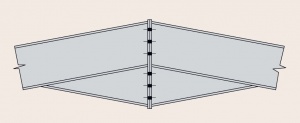
A typical layout of beams around a concrete core is shown in the figure below, with the use of heavier beams at the corner of the core. A double beam may be required to minimise the structural depth at the corner of the cores.
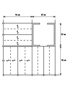
Typical beam layout around a concrete core
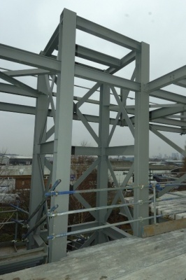
A braced steel core


Braced steel cores may be used as an economic alternative where speed of construction is critical. Such cores are installed with the rest of the steelwork package. An example of a braced steel core is shown in the figure above middle.
Guidance for the design of cast-in steel plates for connecting structural steel beams to concrete core walls is available in SCI-P416. This publication provides a model for the design of simple connections that transfer shear force due to permanent and variable loads and a non-coincident axial tie force resulting from an accidental load case. It points out additional issues which must be considered where coincident shear forces and axial forces are to be dealt with. A sample design of a simple connection for a 610 serial size UB is presented, and the design of punching shear reinforcement for the wall is included. The guide discusses the responsibilities of the building structural engineer and the steelwork contractor and suggests where the responsibilities are best divided. It also considers the impact of deviations between the theoretical positions of the parts of the connection and their as-erected positions.
[top]Columns
Columns in multi-storey steel frames are generally H sections , predominantly carrying axial load. When the stability of the structure is provided by cores, or discreet vertical bracing, the beams are generally designed as simply supported. The generally accepted design model is that nominally pinned connections produce nominal moments in the column, calculated by assuming that the beam reaction is 100 mm from the face of the column. If the reactions on the opposite side of the column are equal, there is no net moment. Columns on the perimeter of the structure will have an applied moment, due to the connection being on one side only. Typical internal column sizes are given in the table below.
| Number of floors supported by column section | Universal Column (UC) serial size |
|---|---|
| 1 | 152 |
| 2 - 4 | 203 |
| 3 - 8 | 254 |
| 5 - 12 | 305 |
| 10 - 40 | 356 |
Although small column sections may be preferred for architectural reasons, the practical issues of connections to the floor beams should be considered. It can be difficult and costly to provide connection into the minor axis of a very small column section.
[top]Structural options for floor systems
A wide range of floor system solutions is available for which typical solutions are given in the table below.
| Form of construction | Typical solution |
|---|---|
| Low rise, modest spans, no restriction on construction depth | Downstand beams
precast units or composite floors |
| Low rise, long span e.g. 15 m | Downstand beams in the façade precast concrete units (15 m), composite floors with secondary steel beams spanning 15 m |
| Medium and high rise, modest spans, no restriction on construction depth | Downstand beams, composite construction |
| Medium and high rise, long spans (to 18 m) restricted construction depth | Composite floors with cellular long span secondary steel beams |
Although steel solutions are appropriate for short spans (typically 6 to 9 m), steel has an important advantage over other materials because long span solutions (between 12 and 18 m) can be easily provided. This has the key advantage of column-free space, allowing future adaptability, and fewer foundations.
Floors spanning onto the steel beams will normally be either precast concrete units , or composite floors. The supporting beams may be below the floor, with the floor bearing on the top flange (often known as 'downstand' beams ), or the beams may share the same zone with the floor construction, to reduce the overall depth of the zone. The available construction zone is often the determining factor when choosing a floor solution.
Beams within the floor zone are known as shallow floor, slim floor or integrated beams. Beams may be non-composite, or composite. In composite construction shear connectors are welded to the top flange of the beam, transferring load to the concrete floor.
Precast concrete units may be used for low rise frames, but composite floors are common in both low rise and high rise structures. Cross laminated timber (CLT) floor slabs are a further option.
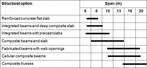
The span range of various structural options in both steel and concrete are illustrated in the table below. Long span steel options generally provide for service integration for spans of over 12 m. Cellular beams and composite trusses are more efficient for long span secondary beams, whereas fabricated beams are often used for long span primary beams.

[top]Estimating steel quantities
For estimating purposes in the design of office buildings, representative weights of steel may be used for buildings of rectangular plan form. These quantities will increase significantly for non rectangular or tall buildings or for buildings with atria or complex façades. The approximate quantities are presented in the table below, and are expressed in terms of the total floor area of the building. They do not include the steelwork used in the façades, atrium or roof.
| Form of Building | Approximate steel quantities
(kg/m² floor area) | |||
|---|---|---|---|---|
| Beams | Columns | Bracing | Total | |
| 3 or 4 storey building of rectangular form | 25–30 | 8–10 | 2–3 | 35–40 |
| 6–8 storey building of rectangular form | 25–30 | 12–15 | 3–5 | 40–50 |
| 8–10 storey building with long spans | 35–40 | 12–15 | 3–5 | 50–60 |
| 20 storey building with long spans and a concrete core | 40–50 | 10–13 | 1–2 | 50–65 |
Further guidance on estimating steel quantities and cost is available.
[top]Factors influencing structural arrangements
The construction programme will be a key concern in any project, and should be considered at the same time as considering the cost of structure, the services, cladding and finishes. The structural scheme has a key influence on programme and cost, and structural solutions which can be erected safely, quickly to allow early access for the following trades.
[top]Site conditions
Increasingly, structures are constructed on 'brownfield' sites, where earlier construction has left a permanent legacy. In city centres, a solution involving fewer, albeit more heavily loaded foundations are often preferred, which lead to longer spans for the superstructure.
[top]Cranes
The number of cranes on a project will be dominated by the site footprint, the size of the project and the use of additional mobile cranes. Multi-storey structures are generally erected using a tower crane, which may be supplemented by mobile cranes for specific heavy lifting operations. In city centre projects, tower cranes are often located in a lift shaft or atrium.
[top]Service integration
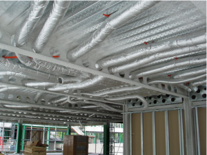

Most large office-type structures require air conditioning or 'comfort cooling', which will necessitate both horizontal and vertical distribution systems. The provision for such systems is of critical importance for the superstructure layout, affecting the layout and type of members chosen. See SCI P166.
The basic decision either to integrate the ductwork within the structural depth or to simply suspend the ductwork at a lower level affects the choice of structural member, the fire protection system, the cladding (cost and programme) and overall building height. Other systems provide conditioned air from within a raised floor.
[top]Single storey buildings

Single storey buildings use steel framed structures and metallic cladding of all types. Large open spaces can be created, which are efficient, easy to maintain and are adaptable as demand changes. Single storey buildings are a 'core' market for steel in the UK.
Single storey buildings tend to be large enclosures, but may require space for other uses, such as offices, handling and transportation, overhead cranes, etc. Therefore, many factors have to be addressed in their design.
Increasingly, architectural issues and visual impact have to be addressed and many leading architects are involved in the design of modern single storey buildings .
[top]Hierarchy of design decisions

The development of a design solution for a single storey building, such as a large enclosure or industrial facility is more dependent on the activity being performed and future requirements for the space than other building types, such as commercial and residential buildings. Although these building types are primarily functional, they are commonly designed with strong architectural involvement dictated by planning requirements and client 'branding'.
The following overall design requirements should be considered in the concept design stage of industrial buildings and large enclosures, depending on the building form and use:
- Space use, for example, specific requirements for handling of materials or components in a production facility
- Flexibility of space in current and future use
- Speed of construction
- Environmental performance, including services requirements and thermal performance
- Aesthetics and visual impact
- Acoustic isolation, particularly in production facilities
- Access and security
- Sustainability considerations
- Design life and maintenance requirements, including end of life issues.
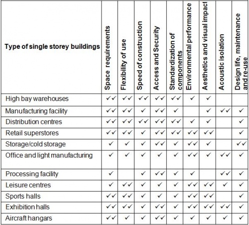
To enable the concept design to be developed, it is necessary to review these considerations based on the type of single storey building. For example, the requirements for a distribution centre will be different to a manufacturing facility. A review of the importance of various design issues is presented in the table on the right for common building types.
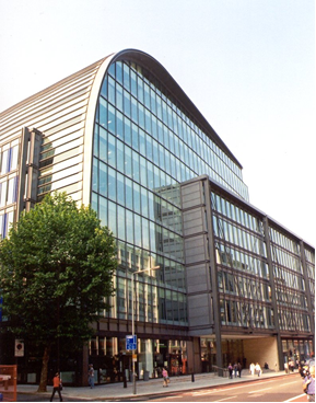
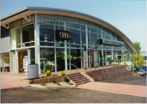
[top]Architectural design
Modern single storey buildings using steel are both functional in use and are designed to be architecturally attractive. Various examples are presented below together with a brief description of the design concept.
[top]Building form
The basic structural form of a single storey building may be of various generic types, as shown in the figure below. The figure shows a conceptual cross-section through each type of building, with notes on the structural concept, and typical forces and moments due to gravity loads.
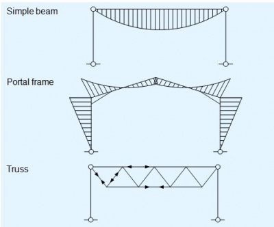

The basic design concepts for each structural type are described below:
[top]Simple roof beam, supported on columns.
The span will generally be modest, up to approximately 20 m. The roof beam may be pre-cambered. Bracing will be required in the roof and all elevations, to provide in-plane and longitudinal stability.
[top]Portal frame
A portal frame is a continuous frame with moment resisting connections to provide stability in-plane. A portal frame may be single bay or multi bay. The members are generally plain rolled sections, with the resistance of the rafter enhanced locally with a haunch. In many cases, the frame will have pinned bases. Stability in the longitudinal direction is provided by a combination of bracing in the roof, across one or both end bays, and vertical bracing in the elevations. If vertical bracing cannot be provided in the elevations (due to industrial doors, for example) stability is often provided by a rigid frame within the elevation.
[top]Trusses
Truss buildings generally have roof bracing and vertical bracing in each elevation to provide stability in both orthogonal directions. The trusses may take a variety of forms, with shallow or steep external roof slopes. A truss building may also be designed as rigid in-plane, although it is more common to provide bracing to stabilise the frame.
[top]Other forms of construction
Built-up columns (two plain beams, connected to form a compound column) are often used to support heavy loads, such as cranes. These may be used in portalised structures, but are often used with rigid bases, and with bracing to provide in-plane stability. External or suspended support structures may be used, but are relatively uncommon.
[top]Choice of building type
Portal frames are considered to be a highly cost-effective way to provide a single storey enclosure. Their efficiency depends on the method of analysis, and the assumptions that are made regarding the restraint to the structural members, as shown in the table below.
| Most efficient | Less efficient |
|---|---|
| Analysis using elastic-plastic software | Elastic analysis |
| Cladding considered to restrain the flange of the purlins and side rails | Purlins and side rails unrestrained |
| Purlins and side rails used to restrain both flanges of the hot-rolled steelwork | The inside flange of the hot rolled steelwork is unrestrained |
| Nominal base stiffness utilised | Nominal base stiffness ignored |
The reasons for choosing simple beam structures, portal frames or trusses are shown in the table below.
| Simple beam | Portal frame | Truss |
|---|---|---|
| Advantages | ||
| Simple design | Long span | Very long spans possible |
| Designed to be stable in plane | Heavy loads may be carried | |
| Member sizes and haunches may be optimised for efficiency | Modest deflection | |
| Disadvantages | ||
| Relatively short span | Software required for efficient design | Generally more expensive fabrication |
| Bracing needed for in-plane stability | Limited to relatively light vertical loading, and modest cranes to avoid excessive deflections | Generally bracing is used for in-plane stability |
| No economy due to continuity | ||
[top]Cladding types
The main types of roofing and wall cladding used in single storey buildings are described as follows:
[top]Roofing
- 'Built-up' or double layer roofing spanning between secondary members such as purlins.
- Composite panels (also known as sandwich panels) spanning between purlins.
- Deep decking spanning between main frames, supporting insulation, with an external metal sheet or waterproof membrane.
[top]Walls
- Sheeting, orientated vertically and supported on side rails.
- Sheeting or structural liner trays spanning horizontally between columns.
- Composite or sandwich panels spanning horizontally between columns, eliminating side rails.
- Metallic cassette panels supported by side rails.
Different forms of cladding (including vertically and horizontally orientated sheets) may be used together for visual effect in the same façades. Brickwork is often used as a 'dado' or 'dwarf' wall below the level of the windows for impact resistance.
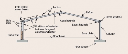
[top]Concept design of portal frames
Steel portal frames are widely used because they combine structural efficiency with functional form. A single-span symmetrical portal frame (as illustrated in the figure below) is typically of the following proportions:
- A span between 15 m and 50 m (25 m to 35 m is the most efficient)
- An eaves height (base to rafter centreline) of between 5 m and 15 m. The eaves height is determined by the specified clear height between the top of the floor and the underside of the haunch.
- A roof pitch between 5° and 10° (6° is commonly adopted)
- A frame spacing between 5 m and 8 m (the greater frame spacings being used in longer span portal frames)
- Members are I sections rather than H sections, because they must carry significant bending moments and provide in-plane stiffness.
- Sections are S355.
- Haunches are provided in the rafters at the eaves to enhance the bending resistance of the rafter and to facilitate a bolted connection to the column.
- Small haunches are provided at the apex, to facilitate the bolted connection.

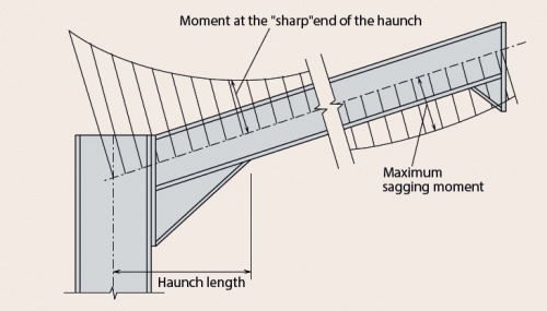
The eaves haunch is typically cut from the same size Standard open sections|rolled section as the rafter, or one slightly larger, and is welded to the underside of the rafter. The length of the eaves haunch is generally 10% of the span. The length of the haunch means that the hogging bending moment at the 'sharp' end of the haunch is approximately the same as the maximum sagging bending moment towards the apex, as shown in the figure below.

The end frames of a portal frame are generally called gable frames. Gable frames may be identical to the internal frames, even though they experience lighter loads. If future extension to the building is envisaged, portal frames are commonly used as the gable frames, to reduce the impact of the structural works. A typical gable frame formed from columns, short simply-supported rafters and vertical bracing, is shown in the figure below.
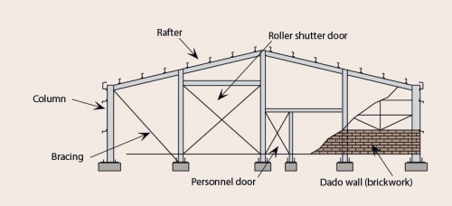

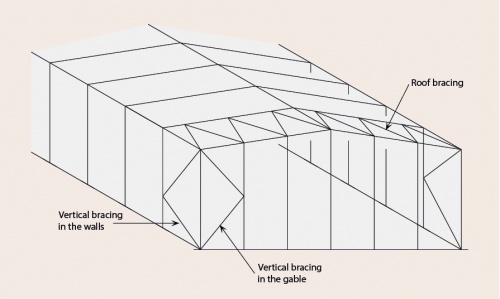
[top]Frame stability
In-plane stability is provided by frame continuity. In the longitudinal direction, stability is provided by vertical bracing in the elevations. The vertical bracing may be at both ends of the building, or in one bay only. Each frame is connected to the vertical bracing by a hot-rolled member at eaves level. A typical bracing arrangement is shown in the figure below.

The gable columns span between the base and the rafter, where the reaction is carried by bracing in the plane of the roof, back to the eaves level, and to the foundations by the vertical bracing. If diagonal bracing in the elevations cannot be accommodated, longitudinal stability can be provided by a rigid frame on the elevation.
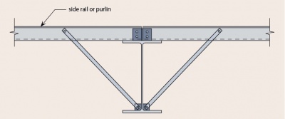
[top]Member stability
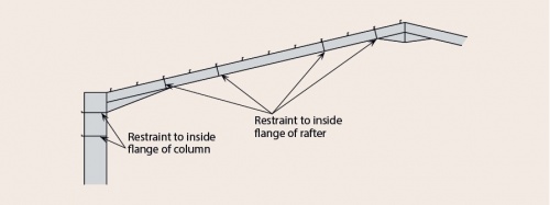

For economic design , restraints to the inside flange of the rafter and column must be considered. The purlins and side rails are considered adequate to restrain the flange that they are attached to, but unless special measures are taken, the purlins and side rails do not restrain the inside flange. Restraint to the inside flange is commonly provided by bracing from the purlins and side rails, as shown in the figure below. The bracing is usually formed of thin metal straps, designed to act in tension, or from angles designed in compression if bracing is only possible from one side. The arrangement of restraints to the inside flange is generally similar to that shown in the figure below and in all cases, the junction of the inside face of the column and the underside of the haunch must be restrained.

[top]Connections
[top]Eaves connection
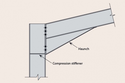

A typical eaves connection is shown in in the figure below. In almost all cases a compression stiffener in the column (as shown, at the bottom of the haunch) will be required. Other stiffeners may be required to increase the bending resistance of the column flange, adjacent to the tension bolts, and to increase the shear resistance of the column web panel. The haunch is generally fabricated from a similar size beam to the rafter (or larger), or fabricated from equivalent plate. Typically, the bolts may be M24 Property Class 8.8 and the end plate 25 mm thick S355.
[top]Apex connection
A typical apex connection is shown in the figure below. The apex connection primarily serves to increase the depth of the member to make a satisfactory bolted connection. The apex haunch is usually fabricated from the same member as the rafter, or from equivalent plate. Typically, the bolts may be M24 Property Class 8.8 and the end plate 25 mm thick S355.

[top]Resources
- Steel Buildings in Europe - Multi-storey buildings: Part 1 Architect’s guide
- Steel Buildings in Europe - Multi-storey buildings: Part 2 Concept design
- Steel Buildings in Europe - Single storey buildings: Part 1 Architect’s guide
- Steel Buildings in Europe - Single storey buildings: Part 2 Concept design
- SCI P166 Interfaces: Design of Steel Framed Buildings for Service Integration, 1997
- Steel Buildings, 2003, (Publication No 35/03), BCSA
- Chapter 3 - Single Storey Buildings
- Chapter 4 - Multi-Storey Buildings
- SCI P167 Architectural Teaching Resource Studio Guide, 2000
- SCI P416 The design of cast-in plates, 2017
[top]See also
- Multi-storey buildings
- Single storey buildings
- Composite construction
- Floor systems
- Long span beams
- Portal frames
- Moment resisting connections
- Service integration
- Building envelopes
- Cost of structural steelwork
- Retail buildings
- Leisure buildings
- Structural fire resistance requirements
- Continuous frames
- Braced frames
- Steel construction products
- Structural robustness
- Trusses
- Fire and steel construction
- Design software and tools