


Cannon Place, London
Structural Steel Design Awards 2011 - Winner
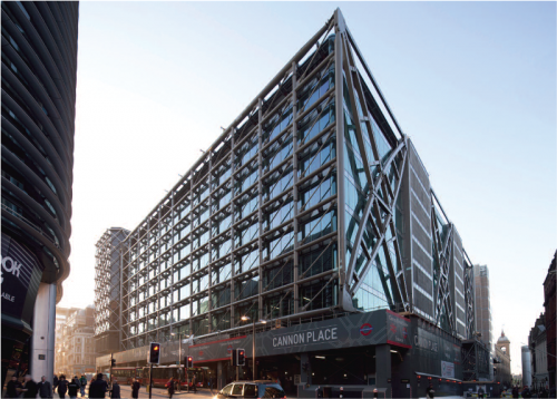

Cannon Place is a 37,000m2 ‘air-rights’ office development in the City of London above Cannon Street mainline and underground stations. The site is broadly rectangular measuring 67.5m x 87m. The brief called for a building which would appeal to financial, legal and corporate tenants, be capable of multiple sub division and optimize the quantum of lettable space on the site.
The site sits in the foreground of protected views of St Paul’s Cathedral, which has the effect of ‘capping’ the height of the scheme at 51.3m AOD. A minimum height of 5.1m above the running tracks of the mainline station had to be maintained. As a result, a height of just 32m existed within which to plan the eight floors of office space needed for commercial viability.
The site was further encumbered by:
- the inability to found vertical structure in the London Undergound tunnels on the north elevation
- significant existing foundations under the previous Cannon Street station facing slab block
- the limitations on column setting out imposed by the mainline railway
- the requirement to minimize foundations in the archaeologically sensitive Scheduled Ancient Monument.
A structural solution was devised which balances a cantilevered 21m deep ‘strip’ of office space to the north with the equivalent accommodation in the south through the use of façade deep transfer structures. This obviates the need for columns in impossible areas and transfer structures, by virtue of their location, do not eat into the development zone and reduce floor to ceiling heights.
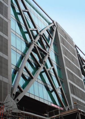
The striking nature of the structure has been expressed by placing the fully glazed curtain wall inside the structural frame allowing the engineering to become the ‘architecture’ of the design. A plan form was devised dividing each of the floorplates into five ‘strips’ of accommodation – three of 21m deep space, separated by two of 12m. At each end of each 12m strip sits a 12m sq fire escape and service core. In the centre of each 12m zone is an atrium which allows daylight to penetrate deep into the heart of the floor plan, each atrium also contains six scenic passenger lifts.
Only columns in these 12m strips continue through the station to foundations. However, in the south atrium the number of columns passing through the station is reduced with transfer structures, a further eight columns terminate above the station acting as ‘link columns’ between the office floors above improving the floors’ dynamic performance.

Floor structures comprise 21m secondary steel beams spanning between 6m or 12m primary beams. All beams are 725 deep Fabsec beams which act compositely with a 130mm lightweight concrete slab on re-entrant metal deck. The deep long-span cellular beams allow the building services to pass through them maximizing floor to ceiling heights.
The north and south façade structures comprise 67.5m long deep trusses, with horizontal and vertical CHSs and diagonal ties that pick up the 21m secondary beams supporting the north and south office fingers. These trusses are supported by cantilever fabricated box section ‘X frames’ along the east and west façades, which are supported at the eastern and western edges of the two founding zones on four 12m x 14m x 1.3m wide composite steel and concrete thick-plate structures, ‘hourglassed’ on three edges to distribute the load evenly to the foundations.
The completed structure had to be within tolerance of a pre-determined line and level to allow installation of the cladding and to align internal elements. Elastic deformations, fabrication and erection tolerances and semi-random variables were assessed and pre-set, deformed shapes were defined - a camber for the north and south façades, and a trapezium for the four ‘Xframe’ cantilevers.
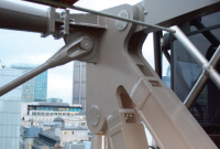
The huge exposed cross frame structures consist of plated box sections with plate thicknesses up to 100mm engineered to be site bolted with exposed pinned connections with just 2mm clearance holes. The accurate fabrication required was achieved with the use of 3D laser equipment and specialized jigs and machining operations. The welding processes were carefully controlled to minimize distortion and each frame was trial assembled during the fabrication process to ensure the pinned fit-up was achieved.
It would have been impossible to build the cantilever ‘X frames’ without some form of temporary support as any dead load deflection during erection would have prevented fit-up of the large diameter pins. However due to restrictions, it was not possible to provide temporary towers under the ends of the cantilever. Instead a method was developed whereby the bottom boom of the façade trusses to each elevation was supported by two sets of 12 sets of cables and strand jacks tied back diagonally to the completed central core area. As the cantilever structure was progressively erected the geometry had to be continually monitored and the strand jacks adjusted to maintain the theoretical shape. Once the frame was fully erected and all the pins installed, the strand jacks were released to allow the structure to cantilever and the floor slabs were cast.
In order to ensure the final load distribution from the ‘hour glass’ structures to the foundations was within the assumed parameters, a controlled minimum load applied through flat jacks was introduced at the base of one end of each “hour glass” structure. The jacks were then filled with resin and the bases were grouted.
The design and construction team have successfully overcome huge design and logistical challenges which would have been impossible without the use of steel.
| Architect | Foggo Associates |
| Structural Engineer | Foggo Associates |
| Steelwork Contractor | Watson Steel Structures Ltd. (now Severfield (UK) Ltd) |
| Main Contractor | Laing O’Roarke |
| Client | Hines |
Judges' comments

This City site has a busy rail terminus, an Underground station and extensive archaeology!
The structural design has only four principal locations for foundations and supports. The façade structure is loadbearing, contributing to the support of the upper floors, onto four massive trunnion columns expressed externally.
The structural concept was heroic, the appearance is striking, and the site constraints were remarkable. A huge challenge, outstandingly well answered with steelwork.