


Building design using steel - a summary for architects
This guidance on building design using steel is aimed at the architectural profession. It explains design issues relevant to key stages of the design process, particularly at the concept design stage. Where relevant, information in the form of rules-of-thumb, tables, details, case examples, etc. provides guidance on the use of steel technologies and evidence to support the architects’ decision-making. It also outlines how the steel construction procurement process works and where advice can be sought from the steel construction industry. A glossary of some of terms used in this article that may be less familiar is also provided.


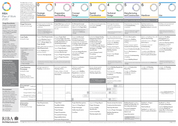
[top]Stages in the RIBA Plan of Work
Main articles: The case for steel, Concept design
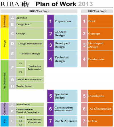

The architectural design process is defined in the 2013 RIBA/CIC Work Stages 1 to 7 which link to the former RIBA Work Stages A to L as shown. The relevant stages that relate to the architectural design concept and the choice of structural form and materials used are:
- Stage 2: Concept design (formerly RIBA Stage C)
- Stage 3: Developed design (formerly RIBA Stage D and E)
- Stage 4: Technical design (formerly RIBA Stage E and F1).
The decision-making process begins with an understanding of the client’s brief and the physical constraints of the project.
The use of steel construction, in its many forms, should be considered at the concept design stage. The decision to use steel is strongly dependent on its ability to create architecturally interesting or long-span solutions combined with savings in the construction programme and its light weight leading to reduced loading on foundations.
Having made the important decisions on the building form at the concept design stage, in essence, the developed design stage provides more detailed information on the building structure, cladding and services, and the technical design stage creates the working details.
In 2020, RIBA launched an updated version of the Plan of Work with similar stage definitions:
- Stage 2: Concept design
- Stage 3: Spacial definition
- Stage 4: Technical design

[top]Client’s brief
Main articles: Concept design, Sustainability, Cost of structural steelwork
The concept design focuses on identifying the client’s requirements for the building and on the involvement of stakeholders including users, local authorities, neighbouring properties and the local community. Key design questions are identified, and the concept design is used as a way of refining the client’s ideas and coming to a workable design solution.
The client’s brief for the project is based on the desired spatial and functional requirements of the building taking account of the physical constraints of the site and any planning requirements. The important types of information are:
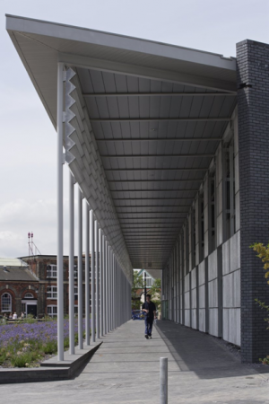
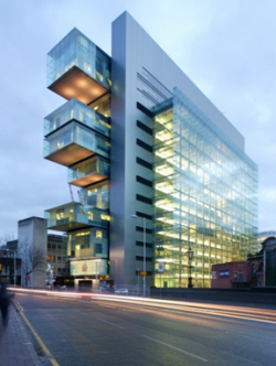
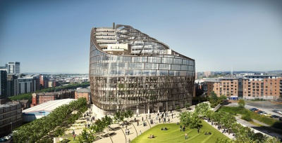
- BREEAM 'excellent' buildings
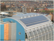
Devonshire Building, University of Newcastle Upon Tyne
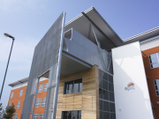
Eliot Park Innovation Centre, Nuneaton

South Cambridge District Council Building, Cambourne
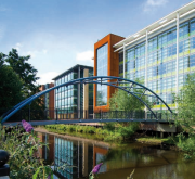
Vulcan House, Sheffield


1. Definition of the physical features of the building and its viability, including:
- Local planning requirements that may influence the building form, including limits on the building height, rights of adjacent properties, access restrictions, renewable energy provisions, appropriate use of cladding materials etc.
- Functional requirements of the space for the client and stakeholders, and other dimensioning criteria, such as, requirements of industrial processes for process buildings, BCO/letting agent’s requirements for offices and Lifetime Homes requirements for residential projects
- External features of the site, e.g. access roads, ground conditions and underground features, and the visual and physical interface with adjacent properties, and constraints on the construction system.
- Options for the building position, shape, height and orientation for the particular site
- Client’s budget, and timescale for the building
2. Description of the design and performance criteria for the project, including:
- Design requirements as influenced by planning and the functional uses of the space etc, as obtained from 1.
- Desired sustainability criteria e.g. BREEAM rating and the building’s operational energy rating, e.g. EPC and DEC rating
- Comfort conditions (internal climate for the various occupancies or activities), and the building envelope design parameters
- Fire safety measures and implications on design e.g. travel distances, smoke control systems and requirements for compartmentation.
Having agreed the physical form and features for the building, and its design or performance requirements, the concept design is then developed to a point where drawings are prepared for more detailed discussion with the client, stakeholders and planners. The concept design will include:
- Architectural or other key visual features of the building e.g. use of an atrium
- Spatial layout and planning grid on each floor based on the functional uses
- Outline of the primary structure, based on the planning grid or process layout.
- External appearance in relation to the cladding options
- Renewable energy and sustainability strategy
- Services strategy and associated plant room space
- More detailed cost schedule.
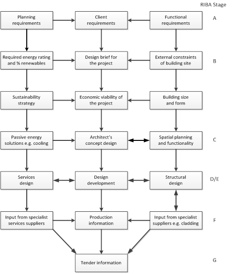
The decision-making process can be complex and is often iterative. The information required and the associated design development for a typical commercial building is shown.

[top]Factors that influence design decisions

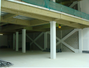
(Image courtesy of Simon Doling/Feilden Clegg Bradley Architects. Copyright Simon Doling/Feilden Clegg Bradley Architects)
Factors that influence design decisions may also be related to the specific building type or function. For example:
- In the commercial building sector, the speculative nature of a development means that a ‘shell and core’ solution may be adopted, in which the Stage 2 fit-out is part of a second contract commissioned by the ultimate user.
- In the education sector and increasingly in the commercial sector, the use of natural ventilation leads to choice of a building form that promotes air movement through the building and the use of solar shading. This may also involve the design of a steel structure that is partially external to the building envelope.
- In the industrial sector the functional requirements of the process will be the principal driver of the design.
Factors that are likely to have a strong effect on the outcome of the design process include:
- Commercial viability of the building project based on the projected income, including the construction programme, implications on cash flow and return on investment. This will extend to marketing of the building in speculative projects.
- Efficient use of the internal space for its functional uses influenced by volume and layout of process equipment, including long spans for flexible internal space use and the integration of a range of services within the structural zones of the building.
- Architectural importance of the project, including the use of expressive structural solutions and materials selection for the visually important parts of the building, such as facades.
- Sustainability strategy and the provision of renewable energy for planning purposes, including passive measures to reduce primary energy use.
[top]Opportunities for architectural expression in steel
Main articles: Simple connections, Moment resisting connections, Visually expressed structural forms, Expressed connections, Use of steel in cladding systems

In addition to being a structurally versatile and adaptable material, steel offers the opportunity for architectural expression. Good quality detailing is vital because it affects structural performance, cost, buildability and, perhaps most importantly, the appearance of the building.
Although the choice of structural form is often the province of the structural engineer, architects should have an appreciation of the factors leading to the selection of the structure and its details. Traditionally, most detailing of connections is the responsibility of the structural engineer or steelwork contractor but, for exposed steelwork, detailing is of much more interest to the architect, as the nature of the connections may impact on the concept of the building.
In this respect, it is important that architects appreciate the common fabrication and erection techniques which may exert a strong influence on the method and approach to the detailing of modern steelwork in buildings.

Steel construction provides many advantages for architectural expression including:
- Externally exposed structures clearly express their function.
- Slender members can be designed efficiently, particularly using tubular sections.
- ‘Lightness’ can be accentuated by openings in beams and by latticework
- Curved members, such as arches, can be formed easily.
- Tension structures are efficient and lightweight, particularly for long span enclosures.
- Connections can be designed expressively.
- The fire resistance of exposed steelwork can be enhanced by the use of intumescent coatings, or by concrete, or water filling (of tubular sections).
- Colours and finishes of painted steelwork can be used to great visual effect.
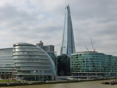
In architecture, the decision to express or conceal the structural frame, either externally or internally, is the result of aesthetic preference coupled with technical and functional considerations.
- Structural Scale
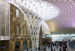
Tubular diagrid structure used over the public concourse at London’s Kings Cross station
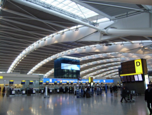
120m long curved fabricated beams used over the Departures area of London’s Heathrow Terminal 5


To achieve economic and practical architectural details, there has to be a basic appreciation of the performance of the overall structure itself and the loading conditions on the member or component in question. The form of the structure will strongly influence the details employed.
Structural details often evolve through the logical stages of the concept design, followed by further rationalisation into the detailed design, i.e. from the macro to the micro. The architect may approach the concept design with the key component details already in mind. However, the final solution will be influenced by structural issues, an understanding of the fabrication process, as well as transport and installation considerations.
Buildings should be designed well at a range of scales. An understanding and an appreciation of all the scales will help in the art of assembly and detailing. Therefore, an elegant and well proportioned building will have been successfully considered at both the large scale as well as in its details. Examples from well-known projects are shown.
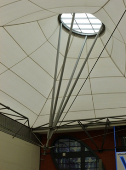
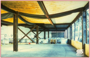
Assembly scale – Expressed use of steel struts and ties to support a tent roof structure at Belfast’s Odyssey
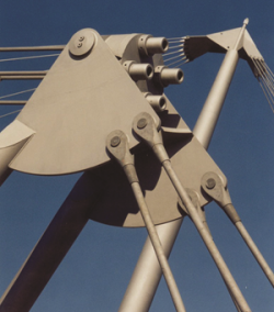
Detail scale – Expressed use of steel nodes and ties to support the roof structure at Manchester’s Etihad Stadium
(Image courtesy of Arup Associates)


[top]Design process in steel construction
Main articles: Design, Concept design, Framing schematics, Member design, Simple connections, Facades and interfaces, Service integration

(Image courtesy of FABSEC Ltd.)
In the context of the design of steel-framed buildings, there are three main stages:
- Concept design, which includes the layout of the main steel components, and the stability strategy for the building, i.e. what is the lateral load resisting system?
- Member design based on structural analysis of the building and on the client’s loading requirements
- Detailed design of connections and interfaces with other components, such as the cladding.
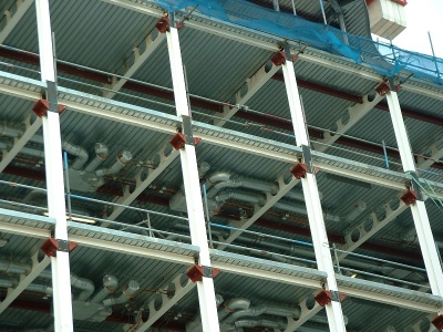
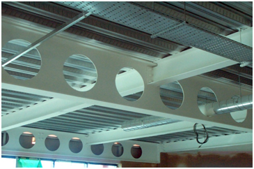
At the detailed design stage, the precise spatial arrangement of all the elements has to be defined and, at the later stages of the design process, it may be necessary to modify the structural layout to accommodate interfaces with other components, such as services. It is now common for long span highly perforated steel beams to be used, which allow for the integration of structure and services within the same horizontal zone through the building.
Two key issues affecting the structural design of the steel frame are:
- Services-structure interfaces, as the detailed services layout is not generally known at the time when the structure is designed
- Cladding interfaces, as the location of the attachment points is unlikely to be known until the later stages of the design process.
Normally the architect and structural engineer agree horizontal and vertical ‘zones’ into which the structure should fit and agree the types of interface details that may be used. Use of long-span beams often means that the number of internal columns can be minimised, and so the optimum location of columns should be part of the concept design process.
Detailing of the building envelope is increasingly important because of its effect on the thermal performance of the building; this also extends to cladding interfaces, roofing and infill walling.
The main contractor is generally responsible for the foundations and any temporary or supporting structures. For these elements, it is necessary to agree geometric tolerances that are appropriate for the particular design solution. The National Structural Steelwork Specification provides useful guidance.
[top]Procurement process
Main articles: Fabrication, Modelling and analysis
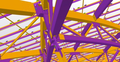

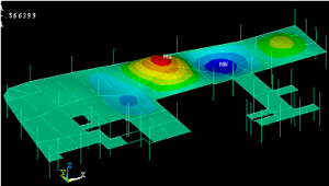
(Image courtesy of Trimble Solutions (UK) Ltd.)
Steelwork contractors can assist in the outline pricing and scheme design of steel structures and can offer advice on practical aspects of the construction process, such as construction programme, temporary works, deliveries to site, etc. The decision to use structural steel is often driven by the programme benefits for which the input from steelwork contractors is essential early in the design process. This is important in major city centre projects where site logistics and just-in-time deliveries are important to the success of the project.
The client’s consulting engineer will normally take the architect’s ‘3D model’ of the building and use the geometry to produce an analytical model to confirm the structural layout and member sizes. Additional information such as the design forces in the connections may be added for later use by the steelwork contractor. This ‘model’ is then transposed into structural and detailing information by the steelwork contractor using well known software packages, such as X steel and StruCAD. In many building projects, the main contractor will manage a Building Information Management (BIM) system into which all the key parties (and especially the steelwork contractor and other specialist sub contractors) will provide their detailing information to enable the BIM model to be updated and act as a comprehensive source of geometric building data for all of the construction ‘team’.
The steelwork contractor will create details of all the connections based on the forces specified by the consulting engineer, and may employ his own consulting engineer for specialist design and temporary works tasks.
The procurement process may be based on competitive tendering in which the key design information is made available to enable pricing by the steelwork contractor. For major projects, the steelwork contractor is able to engage in a two stage design and construction process in which Stage 1 enables the steelwork contractor to contribute to the detailed design and planning process, and Stage 2 to the construction package.
Today, ‘fast track’ construction is the norm in which the steelwork contractor is appointed before all of the detailed design has been completed, and the main contractor is able to procure the steelwork package in such a way as to minimise ‘lead-in’ times and to maximise speed of construction. Often interfaces with cladding, lifts, stairs and other key components are not known at the tendering stage, and so it is accepted that some level of design development is required under the contract.
‘Lean’ construction is also increasingly encouraged by clients in which standardisation of details and components leads to significant economy in manufacture, and to reduction in waste, over-ordering and re work. The concept of off-site manufacture is now well established, which includes the use of a wide range of pre-fabricated components, including large cladding panels, packaged services, room and toilet modules, lifts and stairs, etc.
[top]Sustainability
Main articles: Sustainability, BREEAM, Target Zero

As a material, steel is strong, versatile and infinitely recyclable making it a highly sustainable construction material. As a construction system, steel is lightweight, generates little waste, is fast, safe and cost effective and can be extended or adapted easily.
Sustainability considerations pervade the design and construction process. Sustainability is concerned not only with the operation of the completed building (as defined in sustainability ratings, such as BREEAM), but also with the manufacturing and construction process. It is widely recognised that the off-site nature of steel construction reduces site impacts by its shorter construction programme, and leads to fewer site deliveries, etc. relative to site-intensive construction, and also reduces waste both in manufacture and on site processes.
Steel-framed buildings routinely deliver BREEAM ‘Excellent’ and ‘Outstanding’ ratings and can cost-effectively meet current and likely future low and ‘zero’ operational carbon targets. Importantly steel continues to enable designers to push their limits and deliver iconic buildings that showcase stunning architecture.
The Target Zero design guides provide guidance on the design and construction of sustainable, low and zero carbon buildings in the UK.
[top]Economic solutions in steel
Main articles: The case for steel, Cost of structural steelwork, Cost planning through design stages
The comparative cost of structural steel construction with its main competitor, reinforced concrete, is dependent on taking a holistic view of the financial benefits offered by the speed of construction, the lighter weight and also the longer spans that are offered by using steel. In comparative cost studies of multi-storey buildings, the structural cost of steel and concrete is similar, but the other value benefits offered by steel construction in financial terms, lead to significant savings to the overall project. These additional savings are:
- Speed of construction using steel construction can amount a reduction of to up to 20% in the overall construction period for multi-storey office buildings or hospitals etc. The main savings are in the main contractor’s site preliminaries, and in the cost of borrowing, which together may amount to 3 to 5% of the overall building cost.
- The weight of the structure and floors is typically 50 to 60% of that of a concrete solution. This can lead to reduced foundation costs, which can save 3 to 5% of the total building cost, depending on the complexity of the sub-structure and any underground features.
- Longer spans of 13 to 20m lead to more flexible use of internal space and facilitate future adaptability of that space. A missing internal column can gain 1% additional floor area but more importantly allows the space to be configured (and reconfigured) to the user’s specific requirements as these change over time.
Further savings arise due to reduced site waste, less site accommodation and lower costs as a result of the fewer workers on site, and reduced site operations compared to reinforced concrete construction.
Indicative structural costs are shown. The total cost of the structural elements amounts to approximately 10% of the overall building cost of a commercial building. The accumulated benefit of the speed and material-related benefits can amount to 7 to 10% of the overall construction cost, which is of similar magnitude to the structural costs. Therefore small differences in the cost of the structural solutions are much less important than the wider financial benefits offered by steel construction.
| Type | GIFA Rate (£/m2) BCIS Index 100 | |
|---|---|---|
| Frame | Low rise, short spans, repetitive grid / sections, easy access (55kg/m2 steelwork) | 144 - 175 |
| High rise, long spans, easy access, repetitive grid (90kg/m2 steelwork) | 242 - 274 | |
| High rise, long spans, complex access, irregular grid, complex elements (110kg/m2 steelwork) | 274 - 324 | |
| Floor | Composite floors, metal decking and lightweight concrete topping | 80 - 124 |
| Hollowcore precast concrete composite floor with concrete topping | 121 - 170 | |
| Fire protection | Factory applied intumescent (60 minutes resistance) | 21 - 30 |
| Factory applied intumescent (90 minutes resistance) | 25 - 41 | |
| Portal frames | Large span single storey building with low eaves (6 - 8 m) | 105 - 138 |
| Large span single storey building with high eaves (10 - 13 m) | 128 - 164 | |
Notes:
- ‘Easy access’ is for generally unconfined and regular sites where logistics and access arrangements for delivery and erection are unhindered and straightforward.
- ‘Complex access’ is for confined and irregular site plans commonly found in city centre locations with demanding logistics and access requirements.
[top]Other design issues
Main articles: Fire and steel construction, Corrosion protection, Acoustics, Floor vibrations
[top]Fire safety
Fire safety is an important aspect of the design process and covers both active and passive fire protection systems. Fire protection to structural steelwork takes six generic forms, many of which permit the steelwork members to be visually exposed:
- Spray protection by cementitious materials. The rough appearance of these coatings means that they are normally hidden by a casing or by a suspended ceiling).
- Board protection that forms a ‘box’ around the member.
- Intumescent coatings that are generally in thin film form (up to 2 mm thickness) which follows the exterior form of the profile.
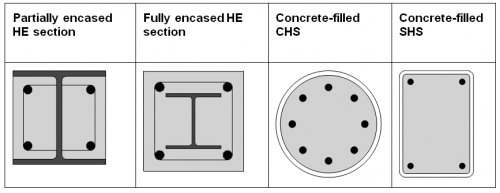
- Concrete encased members, or partially encased H profiles with concrete placed between the flanges.
- Concrete filled hollow sections, generally with additional reinforcement, in which the steel profile is painted and exposed.
- Water filled hollow sections are occasionally used for exposed roofs or exterior steelwork.

The use of intumescent coatings and concrete filled hollow sections provide the greatest opportunity for architectural expression.
Fire engineering is a widely used technique, where fire severity can be predicted based on the fire load, ventilation, fire compartmentation and smoke control criteria. Fire engineering is often used in the design of public spaces, such as airport terminals, which have a low fire load and good means of escape.
Designers of steel structures may also employ what is known as ‘Structural Fire Design’ in which the behaviour of an assembly of steel members and floor slabs is considered as a ‘whole’ as opposed to that of individual members. Based on results of ‘real’ fire tests on an 8 storey steel framed building in the UK, structural fire design has been used to reduce and even eliminate the use of passive fire protection applied to secondary structural members.
Intumescent coatings are increasingly used to protect steelwork, and off site application of these coatings is now common for up to 90 minutes fire resistance. Concrete is also used to protect steelwork, and common examples are slim floor beams, which are partially encased in the floor slab, and also concrete filled tubular columns, which are used for appearance and increased load resistance.
[top]Concrete as fire protection
Examples of the use of partial and full concrete encasement to an H profile and concrete-filled circular hollow sections are shown. Partially encased steel columns generally achieve 60 minutes fire resistance, and concrete filled sections achieve up to 120 minutes fire resistance. Fully encased steel sections achieve longer fire resistance periods.

[top]Boards, spray and intumescent coatings

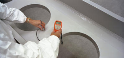
(Image courtesy of Sherwin-Williams Protective and Marine Coatings)
Intumescent coatings are classified as thin film when up to 2 mm thick and thick film for coating thicknesses of 2 to 5 mm. Coatings of up to 2 mm thick can be applied off-site (in the factory) with a high level of quality control on the thickness of intumescent coating. This is commonly used for long span beams requiring up to 90 minutes fire resistance, as shown. A second layer of intumescent coating can also be applied on-site for longer fire resistance periods.


Spray and board materials rely on their low thermal conductivity and resistance to damage in fire. Spray materials are often cementitious-based and so can be thicker than boards. Boards are often in the form of plasterboard with glass fibres, calcium silicate or compressed mineral wool. An example of two types of board fire protection to beams and columns is shown right.
The table presents typical thicknesses of cementitious spray and rigid board fire protection to a 254 x 254 UC column (assuming an effective height of 3.2m)
| Fire resistance | Cementitious spray protection (mm) | Rigid board protection (mm) |
|---|---|---|
| 30 mins | 10 | 12 |
| 60 mins | 20 | 15 |
| 90 mins | 25 | 20 |
| 120 mins | 30 | 25 |
[top]Corrosion protection

Corrosion of steelwork does not occur in warm, dry buildings, such as office buildings, but it is common practice to paint steelwork in roofs or façade members, as it is in unheated parts of buildings, which may be subject to some risk of moisture on the surfaces of the structure. Special corrosion protection systems are required for certain types of applications, such as swimming pools.
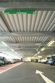
Galvanized steel is used for secondary steel components, such as floor decking, roof purlins and infill walling and is corrosion resistant in internal applications. In addition, plastic coated steel decking for composite flooring applications, such as car parks or buildings exposed to moisture is available. Hot-dip galvanizing can also be used for external steelwork.
[top]Acoustic insulation
Steel composite floors possess excellent acoustic insulation to airborne and impact sound transmission and have achieved the status of a Robust Standard Detail. Light steel separating walls can also be designed to achieve high levels of acoustic performance. Increasingly, reduction of external noise is important in city centre projects and light steel infill walls can provide the required insulation levels.
[top]Vibration control
Control of floor vibrations became an issue in lightweight, open plan floors. To avoid the risk of resonant or repeated vibration effects, guidance was developed by SCI in the early 1990s. This is based on a minimum ‘system’ frequency of 4 cycles/sec to avoid resonant effects of rapid walking at a pace of two strides per second. The floor system includes all secondary and primary beams and also the floor slab (which is very stiff in relation to the beams).

The SCI guidance (P354) also demonstrated that long-span floors are less sensitive to occupant induced vibration effects than shorter span floors due to the higher effective area and weight of the floor that is mobilised. Monolithic two way spanning shallow floor systems, also possess excellent stiffness and low sensitivity to vibrations, so much so that this type of construction is often used in hospitals to satisfy even stricter vibration criteria.
For further guidance on floor vibrations, see Steel Construction: Floor Vibration, and a useful web-based Floor response calculator is also available to swiftly evaluate the vibration response of floors.
[top]Manufacturing and construction issues
Main articles: Fabrication, Construction
Steelwork fabrication and installation are specialist tasks; the main processes involved are outlined below.
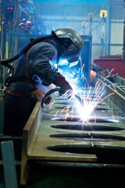
[top]Fabrication processes
Steelwork fabrication processes include:
- Design and detailing of connections and attachments
- Cutting to length beams, columns and bracing and dressing to remove sharp edges and burrs
- Drilling of holes for bolts
- Welding of plates and fitments
- Blast cleaning and painting steelwork
- Attachment of fitments for installation and protection e.g. edge protection
- Manufacture and attachment of secondary components, such as cleats, shims and bolts and lifting lugs
- Curving of members, forming of openings, which is often carried out by specialist companies
- In some cases, partial concrete encasement and shear connector welding in the factory
- Scheduling for delivery on a ‘just in time’ basis and transport from the fabrication workshop to the construction site
- Design of temporary works
- Fabricating a cellular beam
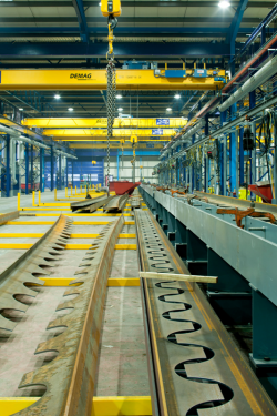
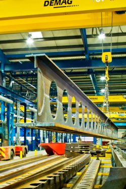


(Images courtesy of Kloeckner Metals UK Westok)
[top]Construction processes
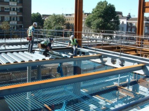

Construction concerns on-site processes, including any temporary works that may be required to facilitate the erection of the structural steelwork. In the context of steelwork this involves:
- Lifting, positioning and ‘line and levelling’ of steel members, particularly in relation to foundations, etc.
- Handling and storage of components on site
- Installation by ‘Mobile Elevating Working Platforms’ (MEWPs), tower cranes, or from hired-in mobile cranes
- Installation of safety barriers and edge protection (that is often pre-attached to the steel beams)
- Installation of decking, shear connectors, and light steel infill walling, depending on the structural system chosen.
[top]Glossary
The following is a glossary of terms relating to structural engineering and structural steelwork.
- Bending moment – The result of actions on a member causing curvature. The bending moment is a measure of the bending effect.
- Bracing – A system of members that provide support at discreet positions within a structure, transferring loads to some fixed positions. Typically, vertical bracing, comprising inclined members, is provided in a building to resist lateral loads, such as wind actions, and to provide stability. Plan bracing may be provided a lateral link between frames, or to provide positional support. Bracing may also refer to the internal members of trusses.
- Braced frames - Structures where the lateral stability is achieved by providing bracing. In this form of frame, the beams are designed as pin-ended. The columns are designed using nominal moments, assuming that the beam reaction acts at a nominal eccentricity (typically 100mm) from the face of the column.
- Edge beam – Beam at the periphery of the structure, which normally supports cladding.
- End plate – Plate welded to the end of a member (typically a beam) to facilitate a bolted connection to another member (a column or a beam). End plates may be partial depth (at least 60% of the beam depth, welded to the web only) or full depth (welded to both flanges) or extended past the flange. Thin, partial depth end plates are used in nominally pinned connections in braced frames. Thicker, full depth or extended end plates are used in moment-resisting connections.
- Fin plate – A thin vertical plate welded to a beam or a column. The fin plate laps with and is bolted to a beam web, forming a nominally pinned connection.
- Lattice girder – A member acting as a beam and consisting of a lattice of elements in which the longitudinal members are the ‘chords’ and the internal inclined elements are the ‘bracing’.
- Major axis connection – A connection made to the major axis of the member. The major axis has the larger second moment of area (or “inertia”).
- Minor axis connection – A connection made to the minor axis of the member. Connections to the minor axis generally involve a connection to the web of the supporting member.
- Moment resisting – Typically, used to describe a rigid connection between members that has been designed to transfer the bending moment between the two members.
- Notching – Cutting away of part of the section at a connection, which normally refers to the cutting of the beam flange.
- Nominally pinned or ‘simple’ connections – Connections whose bending stiffness is small enough to be ignored, with rotation capacity. Nominally pinned connections are generally used in braced frames.
- Rigid or continuous frames – Frames where the resistance to lateral loads is provided by the stiffness of the members and rigid connections. There is no requirement for bracing in a continuous frame.
- Shear forces – Internal forces perpendicular to the longitudinal axis of a member. The shear force due to a uniform load is a maximum at the ends of the member and is transferred by the connections into the support.
- Torsional stiffness – The stiffness of the member to twisting. Hollow sections are very stiff in torsion whereas open sections are less so.
- Truss – A member consisting of a lattice of elements in which the longitudinal elements are the ‘chords’ and the internal inclined elements are the ‘bracing’. Trusses are generally used in roofs and when the roof is pitched, the top chord is also inclined. Different layouts of internal members (the ‘bracing’) may be used.
[top]Further reading
- RIBA plan of work 2013
- Steel Buildings, BCSA No. 35/03, Chapter 4, Multi-Storey Buildings
- Steel Designers' Manual 7th Edition. Editors B Davison & G W Owens. The Steel Construction Institute 2012, Chapter 5, Multi-Storey Buildings
- British Council for Offices Guide to Specification, BCO, 2019
- Architectural Design in Steel – Trebilcock P and Lawson R M published by Spon, 2004
[top]Resources
- Target Zero - Guidance on the design and construction of sustainable, low carbon office buildings
- SCI P101 Interfaces - Steel Supported Glazing Systems
- SCI P166 Interfaces: Design of Steel Framed Buildings for Service Integration, 1997
- SCI P336 Acoustic detailing for multi-storey residential buildings
- SCI P371 Acoustic performance – Case Studies
- SCI P372 Acoustic Detailing for Steel Construction
- SCI Acoustic performance prediction tool for separating floors and walls
- SCI P167 Architectural Teaching Resource Studio Guide, 2000
- SCI P137 Comparative Structure Cost of Modern Commercial Buildings (Second Edition), 2004
- SCI P166 Design of Steel Framed Buildings for Service Integration
- SCI P354 Design of Floors for Vibrations- A New Approach
- Steel Construction: Floor Vibration, BCSA, 2016
- Floor response calculator
- SCI P355 Design of Composite Beams with Large Web Openings
- Best Practice in Steel Construction: Commercial Buildings
- SCI IEP 2 Service Coordination with Structural Beams
- SCI IEP 4 Supporting Services from Steelwork
- Steel Buildings in Europe - Multi-storey buildings:
- Part 1: Architect’s guide
- Part 2: Concept design
- Part 3: Actions
- Part 4: Detailed design
- Part 5: Joint design
- Part 6: Fire Engineering
- Part 7: Model construction specification
- Part 8: Description of member resistance calculator
- Part 9: Description of simple connection resistance calculator
- Part 10: Guidance to developers of software for the design of composite beams
[top]See Also
- Framing schematics
- Visually expressed structural forms
- Expressed connections
- Use of steel in cladding systems
- Sustainability
- Design
- Fabrication
- Cost of structural steelwork
- Corrosion protection
- Acoustics
- Floor vibrations
- Construction
- The case for steel
- Concept design
- Simple connections
- Moment resisting connections
- Member design
- Facades and interfaces
- Service integration
- Modelling and analysis
- BREEAM
- Target Zero
- Cost planning through design stages
- Fire protecting structural steelwork