


Bridge articulation and bearing specification
Articulation is the term for the configuration of bridge supports and choice of structural bearings that provides the necessary restraints to the superstructure whilst at the same time providing freedom to some displacements and rotations in order to avoid unnecessary forces on both the superstructure and substructure due to constraint.
A range of different bearing types is available. Selection of the appropriate type and specification of the forces they must resist and displacements they must permit is a key responsibility for the structural designer.
Clear communication of the requirements for the bearings and for their installation is essential for proper functioning of the structure and for avoidance of unanticipated maintenance issues.

[top]Articulation
Bearings are used to transfer forces from the superstructure to the substructure whilst either tolerating or constraining relative movement. The principal actions that give rise to displacements and rotations at supports are:
- Temperature change (uniform and temperature difference)
- Shrinkage of concrete deck slab
- Permanent actions (dead loads and superimposed dead loads)
- Variable actions – mainly traffic loads
- Vertical loads
- Horizontal loads
- Settlement of supports
- Accidental actions - vehicular collision
Movements can be either permanent (irreversible) or transient (reversible).
Generally, the structure will rotate about longitudinal and transverse axes at its supports and these rotations must either be accommodated in the bearings or the bearings must be designed to resist them (in which case the effects on the structure must also be considered). In some cases, there is also a rotation about a vertical axis (associated with plan bending of the structure) but this is usually small in magnitude.
Horizontal displacements at supports arise both from an overall change in length of the structure and due to bending in a vertical plane (since the centroidal axes are above the levels of the supports). Since it is necessary to resist horizontal forces at at least one position, it is usual to do so by preventing horizontal displacement at that position; this means that horizontal displacements at other positions are due to the expansion/contraction of the length from the fixed bearing and to the (vectorial) sum of the movements due to bending rotation.
The following recommendations relate to the articulation arrangements for typical highway bridges.
As bearings and expansion joints introduce a maintenance liability, it is good practice to limit the number of bearings required and to minimise the movement to be accommodated by an expansion joint. Spans should be arranged so as to avoid uplift at bearing positions (it is a very complex and costly matter to provide restraint against uplift in a bearing), particularly when dealing with skewed structures.
The designer should avoid locking in forces that would hinder bearing replacement. Restraint against longitudinal forces should be provided at one support, with guided restraints aligned to allow movement at the other supports. Similarly, restraint against transverse forces should be provided at only one bearing at each support. The construction sequence of the structure should also be considered, to establish the permanent displacements.
The articulation scheme that the designer chooses should be shown on the drawings and will form the basis of a bearing schedule.
The convention for illustrating the movements and constraints in bearings is given in Table 1 of BS EN 1337-1[1]. A selection of common symbols is given below.
| Symbol in plan | Type of bearing | Relative movements | |||||
|---|---|---|---|---|---|---|---|
| X direction |
Y direction |
Z direction |
About X axis |
About Y axis |
About Z axis | ||
| Elastomeric bearing | deforming | deforming | small | deforming | deforming | deforming | |
| Elastomeric bearing with restraints for one axis | deforming | none | small | deforming | deforming | deforming | |
| Pot bearing | none | none | very small | deforming | deforming | deforming | |
| Pot bearing with unidirectional sliding | sliding | none | very small | deforming | deforming | deforming | |
 |
Pot bearing with multidirectional sliding | sliding | sliding | very small | deforming | deforming | sliding |
Note: Some symbols are due to be modified in a future amendment of BS EN 1337-1[1]. The symbols for elastomeric pot bearings will be solid black, rather than an open square and circle.
[top]Single span bridges
[top]Floating articulation
If a bridge deck is relatively small and the associated horizontal forces are not too big, the deck can effectively “float” on bearings that will each accommodate rotational and translational displacements and will each provide part of the resistance to horizontal forces. The bearings for this articulation arrangement will be elastomeric bearings. All horizontal forces and movements are then accommodated by shear deformation of the bearings.


[top]Articulation from a fixed point
Most bridges will require some form of mechanical restraint to resist the horizontal forces and ensure that thermal expansion and contraction occurs in the right direction. This is most easily achieved using pot bearings.
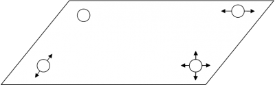

The arrangement above shows the layout for a simple single span structure with skew. The bridge deck is fixed in one corner and horizontal movements are controlled by the use of guided (unidirectional) bearings. A free (multidirectional) bearing is provided for the diagonally opposite corner to the fixed bearing. Longitudinal forces are taken by both the fixed and guided bearing at the “fixed” end of the span. In a wider deck, it would be preferable to locate the fixed bearing closer to the centre of the deck so as to minimise the relative transverse movement and thus limit the movements to be accommodated by the expansion joint.
[top]Continuous multi-span decks
For longer spans, the magnitude of the movements increases and therefore these should be minimised by locating the fixed bearing at the centre of the bridge to ensure the thermal expansion is split between each end of the bridge. Care should be taken to ensure that the pier is designed for the resulting horizontal forces, particularly from braking and acceleration actions.


On multi-span structures, care should be taken to ensure movements are not restrained, however the use of slender piers that are able to flex may allow for load sharing between bearings at a support location.
Further examples of bridge articulation arrangement are given in Guidance Note 1.04.
[top]Curved bridge decks
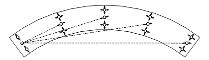

Curved decks can be guided either radially from a fixed point or tangentially to the radius of curvature. If the deck is guided radially, then the accuracy of the geometry becomes critical for the bearings furthest from the fixed point.
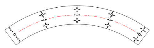
For structures with a constant curvature it is best to align the bearings tangentially to effectively guide the deck around the curve as it expands and contracts. The resulting horizontal forces are often accommodated by the use of specific guide bearings which may not be vertical load carrying.

[top]Expansion joints
Most historic bridges had no specific means of articulation between the deck and substructure: movements would produce local cracking at the abutments. In modern bridges, articulation arrangements, such as those described above, accommodate thermal and other movements by selecting appropriatebearings as ‘fixed’ and allowing controlled movements to take place elsewhere. At road level, these movements are accommodated by an expansion joint, which isolates the abutments from the displacements and maintains the integrity of the surfacing at the end of the bridge.
The bridge designer should specify the expansion joints in a similar manner to bearings, giving details of characteristic and design values of displacements to the joint designer.
Annex B of BS EN 1993-2[2] contains guidance for the preparation of a technical specification for expansion joints.
By introducing bearings, and particularly by introducing expansion joints at road level, a significant maintenance liability is created. To reduce such liability, ‘integral construction’ is often considered for short bridges. For example, CD 350[3] currently recommends that integral construction be considered for all bridges up to 60m overall length and less than 30° skew. This reduces, and in some cases eliminates, the need for maintenance but the designer must still consider the movements (displacements and rotations) that are induced by traffic and thermal actions and make appropriate allowances.
[top]Bearings
The product standard for bearings is BS EN 1337 and this is the standard referred to in the Eurocodes. BS EN 1337 comprises 11 Parts, of which the most relevant are:
- Part 1: General rules[1]
- Part 2: Sliding elements[4]
- Part 3: Elastomeric bearings[5]
- Part 5: Pot bearings[6]
- Part 8: Guide bearings and restraint bearings[7]
The choice of bearing will be governed by both the values and directions of the actions and also by the magnitude and directions of the allowed and restrained displacements. Typical load bearing capacities (at ULS) are tabulate below.
Further guidance on the types of bearings and their usage can be found in Guidance Note 3.03.
| Type | Load capacity (kN) | Comments | |
|---|---|---|---|
| Elastomeric | Strip | 200 – 1,000 | Limited translation and rotation, and used only for very short spans and light loads |
| Pad | 10 – 500 | ||
| Laminated | 100 – 1,000 | Widely used for short spans | |
| Pot | 500 – 30,000 | Proprietary product, widely used on steel bridges | |
| Line rocker | 1,000 – 10,000 | No lateral rotation, fixed bearings, rail bridges, large longitudinal rotation | |
| Spherical | 1,000 – 12,000 | Expensive, large rotation capacity, used on major steel bridges | |
[top]Elastomeric bearings
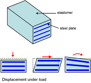

Elastomeric bearings normally consist of a number of rubber layers separated by steel plates. These are normally laid in pads or strips and are ideally suited for small structures. They accommodate movements by deformation. It is not normally required to fix the bearing in place as friction between the rubber and the support surfaces will normally be adequate.
Elastomeric bearings provide an excellent economic solution for applications where structure movements, longitudinal, transverse and rotational are small. They provide vibration isolation and are generally simple to install. Elastomeric bearings are relatively maintenance free but will degrade over time and require replacement.
Larger movements require taller bearings and possibly additional mechanical means of preventing the bridge deck from effectively floating from the desired position. When used on steel bridges, elastomeric bearings can be positively located using perimeter keep strips welded to the underside of the bottom girder flange.
[top]Pot bearings
The elastomeric pot bearing consists of a confined disk of elastomer within a short cylinder (the pot). Loading is then applied via a close fitting steel ‘piston’. This puts the elastomer under high pressure, making it behave like a liquid, permitting rotation in any direction with very little resistance.
A sliding surface can be included to accommodate translational movement, which can be in any direction or constrained by guides. The rotations and the translations, as well as the loads carried, can be greater than for elastomeric bearings.


[top]Other bearing types
[top]Spherical bearings
Spherical bearings are used to accommodate large rotations by the use of a lower spherical surface. This is normally lined with dimpled PTFE and matched to an upper stainless steel surface. These types of bearings are more expensive than pot bearings due to the increased machining and would only be used on major structures, to accommodate increased deck rotations. Generally, these bearings require a minimum co-existent vertical load to prevent instability.
- Spherical bearings
Plain spherical bearing
Spherical bearing with sliding guided element


[top]Rocker bearings

These bearings allow rotation about a single axis (usually transverse to the girder). The advantage of these bearings is that torsional restraint is provided about the axis orthogonal to the line of contact and therefore can be useful in U frame bridges. They are often used when impact loading is high, such as on railway bridges.
[top]Guide bearings
As the name suggests, these bearings are used to ensure the structure maintains the correct location or expansion/contraction path and take no vertical load. These types of bearings are occasionally used on heavily skewed or multispan structures.

[top]Bearing specification
It is the bridge designer’s responsibility to prepare the bearing schedule. The schedule should contain the following information:
- A list of forces on the bearings from each action
- A list of movements of the bearings from each action
- Other performance characteristics of the bearings
The bearing designer (normally the manufacturer) will then use this information to determine the design values and therefore the full specification.
There are currently two alternative templates given for the bearing schedule, one is given in Table A.3 of Annex A of BS EN 1993-2[2] and the other in Table B.1 Annex B of BS EN 1337-1[1].
Table A.3 of BS EN 1993-2[2] requires the designer to give characteristic values due to the separate actions, which then need to have partial and combination factors applied to them to give the design value for the bearings. Generally, the bearing designer will be unaware of the relevant design combinations and will thus not be able to determine design values for the bearings from these characteristic values.
Table B.1 of BS EN 1337-1[1] simply expects the designer to give the relevant design values of ‘loads’ (forces on the bearings ) and displacements. This schedule also requires reference data, maximum dimensions and fixing details to be indicated. This is more informative for the bearing designer but still does not give the full range of coexisting combination of forces and displacements for each bearing. (This deficiency will be addressed in the planned Amendment to BS EN 1337-1[1], which will give new schedule tables.)
| Structure Name or Reference | |||||||||
| Bearing Identification Mark | |||||||||
| Type of Bearing (see Table 1 of BS EN 1337-1)[1] | |||||||||
| Number off | |||||||||
| Seating Material | Upper Surface | ||||||||
| Lower Surface | |||||||||
| Average Design Contact Pressure (N/mm2) (Capacity of structure) |
Upper Face | Serviceability | |||||||
| Ultimate | |||||||||
| Lower Face | Serviceability | ||||||||
| Ultimate | |||||||||
| Design Load Effects (kN) | Serviceability Limit State | Vertical | Max. | ||||||
| Perm. | |||||||||
| Min. | |||||||||
| Transverse | |||||||||
| Longitudinal | |||||||||
| Ultimate Limit State | Vertical | ||||||||
| Transverse | |||||||||
| Longitudinal | |||||||||
| Displacement (mm) | Serviceability Limit State | Irreversible | Transverse | ||||||
| Longitudinal | |||||||||
| Reversible | Transverse | ||||||||
| Longitudinal | |||||||||
| Ultimate Limit State | Irreversible | Transverse | |||||||
| Longitudinal | |||||||||
| Reversible | Transverse | ||||||||
| Longitudinal | |||||||||
| Rotation (Radians) | Serviceability Limit State | Irreversible | Transverse | ||||||
| Longitudinal | |||||||||
| Reversible | Transverse | ||||||||
| Longitudinal | |||||||||
| Maximum Rate (Radians / 100kN) |
Transverse | ||||||||
| Longitudinal | |||||||||
| Maximum Bearing Dimensions (mm) | Upper Surface | Transverse | |||||||
| Longitudinal | |||||||||
| Lower Surface | Transverse | ||||||||
| Longitudinal | |||||||||
| Overall Height (mm) | |||||||||
| Tolerable movement of bearing under transient loads (mm) | Vertical | ||||||||
| Transverse | |||||||||
| Longitudinal | |||||||||
| Maximum acceptable reaction to displacement under serviceability limit state (kN) | Transverse | ||||||||
| Longitudinal | |||||||||
| Maximum acceptable reaction to rotation under serviceability limit state (kNm) | Transverse | ||||||||
| Longitudinal | |||||||||
| Type of fixing required | Upper Face | ||||||||
| Lower Face | |||||||||
The designer must be aware of the difference between the two schedules and ensure that adequate information is supplied to the bearing supplier. It is also important, for correct installation, that the orientation of the bearing is clear; see advice in Guidance Note 2.09.
It is important to note that, for steel bridges, the bearings are normally installed before completion of the bridge deck and therefore bearings will have to accommodate additional thermal displacements and also movements due to construction activities. A common situation that must be considered is rotation due to pre-camber and the drop-out during construction, particularly in heavily skewed structures where may be large transverse rotations at the supports. These rotations are a function of the plan geometry and are related to the magnitude of the dead load effects and the pre-camber provided, they cannot be avoided.
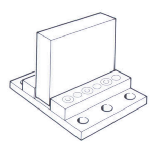
[top]Bearing installation
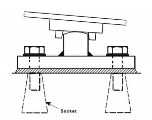
Bearings are normally bolted to the girders above and the substructure below to allow replacement. Normally the bearing surface is set to be horizontal and therefore “taper” plates are normally required to follow the geometry of the steelwork above. These “taper” plates should be designed along with the main girders, taking into account the final geometry of the bridge post camber. The bearings are normally bolted through the girder bottom flange though difficulties do arise with thick flanges and moderate to large gradients since it is only feasible to drill square to the flange surface. A common solution to this problem is to use tapped holes in the taper plate, which is then welded to the underside of the girder; when using this detail, the horizontal forces on the bearing need to be minimised. Refer to Guidance Note 2.08 for more information.
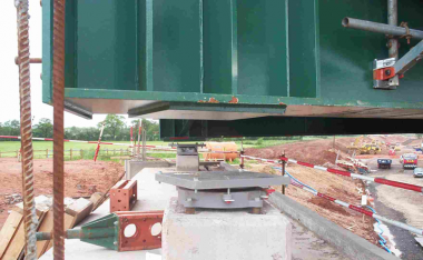
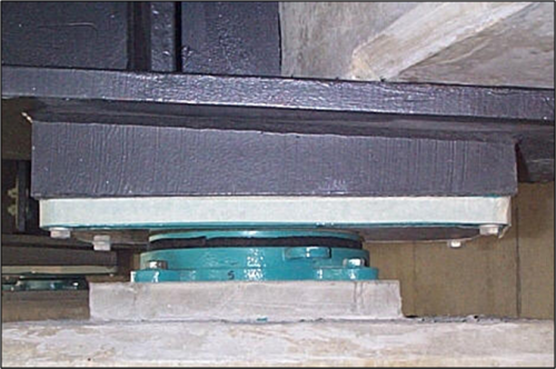
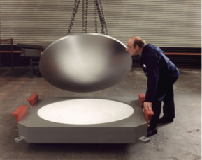
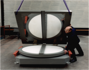
Skew ladder deck being lowered onto an elastomeric pot bearing
(Image courtesy of Arup)
Attachment of bearing by bolting through girder flange


[top]Initial temperature and temperature range
An estimate for the initial installation temperature for the installation of the bearing should be given by the designer to the constructor enable the bearing to be set correctly prior to installation, in order to allow the full expansion and contraction displacements to be accommodated. This is not explicitly stated in Annex B of BS EN 1337-1[1] but is stated in Annex A of BS EN 1993-2[2]. Some guidance for this installation temperature and the associated temperature range is found in the Eurocodes but there remains some potential confusion. The following is an attempt to guide the designer through the relevant parts of the Eurocodes relating specifically to bearings and expansion joints as the onus is on the designer to specify the range of displacement at the ultimate limit state.
An initial bridge Temperature T0 is given in the National Annex to BS EN 1991-1-5[8], clause NA.2.21 states that "In the absence of specific provisions to control the temperature at which a bridge is restrained, the initial temperature T0 should be taken as 0°C for expansion and 20°C for contraction." This would then be taken in conjunction with BS EN 1991-1-5[9] clause 6.1.3.3 (3) Note 2 for bearings which adds 20°C to both the expansion and contraction range of the uniform temperature component if no further information is available. This may be reduced to an additional 10°C if an initial installation temperature is specified. However, clause NA.2.6 of the National Annex to BS EN 1991-1-5[8] then points the designer to BS EN 1993-2[2].
Annex A of BS EN 1993-2[2] requires a reference T0 to be calculated as above. The uncertainty of the position of a sliding bearing at installation should be accounted for by adding ΔT0 as described in Table A.4. The design value for temperature difference is then determined by adding ΔT0 to ΔTK and including a safety term ΔTy, which is given as 5°C.
It is sensible to give the assumed installation temperature, so as to reduce the temperature range of the bearings – a value should be selected to be such that the temperature expansion and temperature contraction are similar (i.e. in the middle of the range), a value for T0 of 10°C would be reasonable.
Using this installation temperature T0 of 10°C as the reference temperature will give similar but not identical results for both methods. As the designer should use the temperature ranges given to estimate the maximum reversible displacements, there is scope for conservatism here without undue cost.
Verification of the initial installation temperature on site will need to be made in accordance with BS EN 1337-11[10].
Further guidance on how designers should calculate the movement range to be specified for bridge bearings, taking account of both thermal change and uncertainty in the relative positioning of bearings on the sub- and superstructures, is available in SCI P406.
[top]Maintenance of bearings


Clause A.3.1 (6) of BS EN 1993-2[2] states that bearings and supports should be designed in such a way that they can be inspected, maintained and replaced if necessary. To achieve this, access for inspection must be provided, there must be means to relieve the bearings of load, and it must by physically possible to extract the old and insert a new bearing.
At an abutment, a common design feature that facilitates inspection and maintenance of the bearings is the abutment gallery. An example of the arrangement for a composite bridge is shown right.
[top]References
- ↑ 1.0 1.1 1.2 1.3 1.4 1.5 1.6 1.7 1.8 1.9 BS EN 1337-1:2000. Structural bearings. General design rules. BSI
- ↑ 2.0 2.1 2.2 2.3 2.4 2.5 2.6 BS EN 1993-2:2006 Eurocode 3 - Design of steel structures: Steel Bridges. BSI
- ↑ CD 350, The design of highway structures. The Design Manual for Roads and bridges. The Stationary Office
- ↑ BS EN 1337-2:2004. Structural bearings. Sliding elements. BSI
- ↑ BS EN 1337-3:2005. Structural bearings. Elastomeric bearings. BSI
- ↑ BS EN 1337-5:2005. Structural bearings. Pot bearings. BSI
- ↑ BS EN 1337-8:2007. Structural bearings. Guide bearings and restraint bearings. BSI
- ↑ 8.0 8.1 NA to BS EN 1991-1-5:2003. UK National Annex to Eurocode 1: Actions on structures: General actions. Thermal actions. BSI
- ↑ BS EN 1991-1-5:2003. Eurocode 1: Actions on structures: General actions. Thermal actions. BSI
- ↑ BS EN 1337-11:1998. Structural bearings. Transport, storage and installation. BSI
[top]Further reading
- Hendy, C.R.; Murphy, C.J. Designers Guide to BS EN 1993-2 Eurocode 3: Design of steel structures. Part 2 Steel bridges. Thomas Telford Ltd.
- Hayward, Alan; Weare, Frank. (1989) Steel Detailer’s Manual. BSP.
- Ray, S.S; Barr, J.; Clark, L. (1996) Bridge detailing guide. (Report R155) CIRIA.
- Souby, M. (2001) Bridges – design for improved durability. (Report C543) CIRIA.
[top]Resources
- Iles, D.C. (2010) Composite highway bridge design. (P356 including corrigendum, 2014). SCI
- Section 8.8
- Hendy, C.R.; Iles, D.C. (2015) Steel Bridge Group: Guidance Notes on best practice in steel bridge construction (6th Issue). (P185). SCI
- Steel Bridges: A practical approach to design for efficient fabrication and construction. (51/10). BCSA
- Section 3.10: Bearings
- Iles, D.C. (2015) Determining design displacements for bridge movement bearings. (P406, 2015). SCI